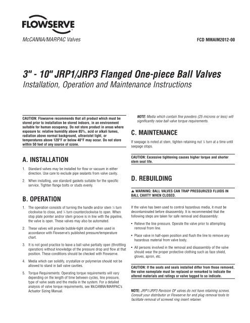
3" - 10" JRP1/JRP3 Flanged One-piece Ball Valves - Flowserve ...
3" - 10" JRP1/JRP3 Flanged One-piece Ball Valves - Flowserve ...
3" - 10" JRP1/JRP3 Flanged One-piece Ball Valves - Flowserve ...

Create successful ePaper yourself
Turn your PDF publications into a flip-book with our unique Google optimized e-Paper software.
McCANNA/MARPAC <strong>Valves</strong> FCD MMAIM2012-00<br />
3" - 10" <strong>JRP1</strong>/<strong>JRP3</strong> <strong>Flanged</strong> <strong>One</strong>-<strong>piece</strong> <strong>Ball</strong> <strong>Valves</strong><br />
Installation, Operation and Maintenance Instructions<br />
CAUTION: <strong>Flowserve</strong> recommends that all product which must be<br />
stored prior to installation be stored indoors, in an environment<br />
suitable for human occupancy. Do not store product in areas where<br />
exposure to: relative humidity above 85%, acid or alkali fumes,<br />
radiation above normal background, ultraviolet light, or<br />
temperatures above 120°F or below 40°F may occur. Do not store<br />
within 50 feet of any source of ozone.<br />
A. INSTALLATION<br />
1. Standard valves may be installed for flow or vacuum in either<br />
direction. Use care to exclude pipe sealants from valve cavity.<br />
2. When installing, use standard gaskets suitable for the specific<br />
service. Tighten flange bolts or studs evenly.<br />
B. OPERATION<br />
1. The operation consists of turning the handle and/or stem 1 /4 turn<br />
clockwise to close, and 1 /4 turn counterclockwise to open. When<br />
stop plate pointer and/or stem groove is in line with the pipeline,<br />
the valve is open. These valves may also be automated.<br />
2. These valves will provide bubble-tight shutoff when used in<br />
accordance with <strong>Flowserve</strong>’s published pressure/temperature<br />
chart.<br />
3. It is not good practice to leave a ball valve partially open (throttling<br />
operation) without knowledge of the pressure drop and flow at that<br />
position. These conditions should be checked with <strong>Flowserve</strong>.<br />
4. Media which can solidify, crystallize or polymerize should not be<br />
allowed to stand in ball valve cavities.<br />
5. Torque Requirements: Operating torque requirements will vary<br />
depending on the length of time between cycles, line pressure,<br />
type of valve seats and the media in the system. For a detailed<br />
analysis of valve torque requirements, see McCANNA/MARPAC’s<br />
Actuator Sizing Manual.<br />
NOTE: Media which contain fine powders (25 microns or less) will<br />
significantly raise ball valve torque requirements.<br />
C. MAINTENANCE<br />
If seepage is noted at stem, tighten retaining nut 1 /6 turn at a time until<br />
seepage stops.<br />
CAUTION: Excessive tightening causes higher torque and shorter<br />
stem seal life.<br />
D. REBUILDING<br />
a WARNING: BALL VALVES CAN TRAP PRESSURIZED FLUIDS IN<br />
BALL CAVITY WHEN CLOSED.<br />
If the valve has been used to control hazardous media, it must be<br />
decontaminated before disassembly. It is recommended that the<br />
following steps are taken for safe removal and disassembly:<br />
• Relieve the line pressure. Operate the valve prior to attempting<br />
removal from line.<br />
• Place valve in half-open position and flush the line to remove any<br />
hazardous material from valve body.<br />
• All persons involved in the removal and disassembly of the valve<br />
should wear the proper protective clothing such as face shield,<br />
gloves, apron, etc.<br />
CAUTION: If the seats and seals installed differ from those removed,<br />
the valve nameplate must be replaced or remarked to indicate the<br />
altered materials and ratings or valve tagged to so indicate.<br />
NOTE: <strong>JRP1</strong>/<strong>JRP3</strong> Revision OF valves do not have retaining screws.<br />
Consult your distributor or <strong>Flowserve</strong> for end plug removal tools to<br />
facilitate removal of screwed ring insert retainer.
1. a. Disassembly of Valve:<br />
1) Place valve in open position. Unscrew all flange bolts or<br />
studs and nuts and remove valve from line.<br />
2) With valve in closed position, remove end plug retaining<br />
screws.<br />
3) Remove end plug. If necessary, drive end plug from valve<br />
using wooden drift applied to ball.<br />
4) Remove body seal, ball, seats and seat back seals (if<br />
any).<br />
b. Removing Stem Assembly:<br />
GENERAL NOTE: Due to different valve series and body styles,<br />
one or two metal stem centering washers may be used and<br />
the stem seal may be one-<strong>piece</strong> or three-<strong>piece</strong>.<br />
1) Remove handle assembly (if any) by loosening handle<br />
screw.<br />
2) Remove retaining nut. Prevent stem from rotating by<br />
holding stem with wrench.<br />
3) Remove stop or valve stem spacer (actuated valves).<br />
Remove and discard Belleville washer(s) (if any). Remove<br />
and retain the follower.<br />
4) Push stem into body cavity and remove. Remove stem<br />
seal(s), stem seal protector (if any) and thrust bearing.<br />
Remove and retain stem centering washer(s).<br />
c. Visual Inspection:<br />
1) The ball and the surfaces against which the seats and<br />
seals are installed should be undamaged, clean and free<br />
of pit marks and scratches. Light marring from the action<br />
of the ball against the seats is normal and will not affect<br />
the operation of the valve. Flaws which can be seen but<br />
barely detected with finger tips are acceptable.<br />
2) The stem and body surfaces that the thrust bearing and<br />
stem seals contact, must be undamaged, clean and free<br />
of pit marks and scratches.<br />
d. Reassembly:<br />
CAUTION: Care must be used when handling graphite stem<br />
seals, thrust bearing, body seals and seat back seals.<br />
These parts can be easily damaged by squeezing the O.D.<br />
of the seal. Parts are to be handled on the flat surfaces<br />
rather than the O.D. These parts will not work if they are<br />
cracked or broken. Light flaking of the material is<br />
acceptable. If resistance is encountered when installing<br />
stem seals over the stem, use follower to gently push the<br />
stem seal down.<br />
1) Lightly lubricate the ball, seats, seat back seals (if used),<br />
body seal, stem seal(s), stem seal protector (if any) and<br />
thrust bearing with a lubricant compatible with media<br />
Flow Control Division<br />
McCANNA/MARPAC <strong>Valves</strong><br />
being handled. White petroleum jelly is a good general<br />
purpose lubricant.<br />
2) To reassemble stem, reinstall stem centering washer(s)<br />
into the recesses in the body. When only one washer is<br />
used, it goes inside recess on top of the body and under<br />
the stem seal(s). Place new thrust bearing onto stem and<br />
insert through body cavity. The thrust bearing can be<br />
distinguished from the stem seals by the darker color of<br />
the 25% filled fluoropolymer used in the thrust bearing.<br />
Assemble new stem seal(s) over the top of the stem and<br />
down into the recess in the top of the body. The follower<br />
is installed on top of the stem seal(s). For valves with<br />
graphite stem seal(s), the stem seal is metallic silver gray<br />
and thicker than the thrust bearing. A Belleville washer is<br />
also added, concave side up over follower (3” - 8” sizes<br />
only). Place stop (or spacer) onto valve stem.<br />
3) When stem assembly is complete, place retaining nut<br />
onto stem. Using handle or wrench to prevent rotation,<br />
tighten retaining nut to fully compress packing or fully<br />
flatten Belleville(s), if used, then back off 1 /6 turn.<br />
Excessive tightening causes higher torque and shorter<br />
stem seal life.<br />
4) Insert far seat and seat back seal (if any) in body. Make<br />
sure seat rests firmly on back surface of recess. If the<br />
seat back seal is not correctly positioned it could be<br />
damaged or cause the valve to leak.<br />
5) With valve in closed position (stop plate pointer and/or<br />
stem groove going across the pipeline), insert ball into<br />
body so that stem slot engages tang on stem.<br />
6) Install and make sure body seal rests squarely on seal<br />
surface of body.<br />
CAUTION: If the body seal is installed on the end plug,<br />
it will be damaged. Insert seat and seat seal (if any) in<br />
recess of end plug, and slide the end plug into the body<br />
as far as it will go.<br />
7) Secure end plug in place by threading in the end plug<br />
retaining screws and tightening each one firmly. Proper<br />
installation will allow no more than .010 protrusion of the<br />
end plug beyond the valve body.<br />
8) Replace handle assembly (wrench block and extension)<br />
and tighten hex head screw (manual valves only).<br />
9) Upon reinstallation of the valve in the line, retighten the<br />
end plug retaining screws after the flange bolts are fully<br />
torqued.<br />
After the valve is assembled, it should be cycled a few<br />
times to ensure that the valve operates smoothly with no<br />
chattering of the ball. The normal operation is an initial<br />
high torque to “break” from the closed position to a<br />
smooth running lower torque mid-cycle, to a high torque<br />
at the end of the 90° cycle or open position. The torque is<br />
similar when closing.<br />
2 3"-10" <strong>JRP1</strong>/<strong>JRP3</strong> <strong>Flanged</strong> <strong>One</strong>-<strong>piece</strong> <strong>Ball</strong> <strong>Valves</strong> FCD MMAIM2012-00
3"–10" 150# and 300# <strong>Flanged</strong> Construction<br />
Flow Control Division<br />
McCANNA/MARPAC <strong>Valves</strong><br />
NOTE:<br />
FLANGED VALVE IS SHOWN.<br />
*THIS WASHER IS NOT USED ON ALL VALVE STYLES, USE EXISTING WASHER WHEN PRESENT.<br />
FCD MMAIM2012-00 3"-10" <strong>JRP1</strong>/<strong>JRP3</strong> <strong>Flanged</strong> <strong>One</strong>-<strong>piece</strong> <strong>Ball</strong> <strong>Valves</strong> 3
Flow Control Division<br />
McCANNA/MARPAC <strong>Valves</strong><br />
<strong>Flowserve</strong> Corporation has established industry leadership in the design and manufacture of its products. When properly selected, this <strong>Flowserve</strong> product is designed to perform its intended function<br />
safely during its useful life. However, the purchaser or user of <strong>Flowserve</strong> products should be aware that <strong>Flowserve</strong> products might be used in numerous applications under a wide variety of industrial<br />
service conditions. Although <strong>Flowserve</strong> can (and often does) provide general guidelines, it cannot provide specific data and warnings for all possible applications. The purchaser/user must therefore<br />
assume the ultimate responsibility for the proper sizing and selection, installation, operation, and maintenance of <strong>Flowserve</strong> products. The purchaser/user should read and understand the Installation<br />
Operation Maintenance (IOM) instructions included with the product, and train its employees and contractors in the safe use of <strong>Flowserve</strong> products in connection with the specific application.<br />
While the information and specifications contained in this literature are believed to be accurate, they are supplied for informative purposes only and should not be considered certified or as a guarantee of<br />
satisfactory results by reliance thereon. Nothing contained herein is to be construed as a warranty or guarantee, express or implied, regarding any matter with respect to this product. Because <strong>Flowserve</strong><br />
is continually improving and upgrading its product design, the specifications, dimensions and information contained herein are subject to change without notice. Should any question arise concerning<br />
these provisions, the purchaser/user should contact <strong>Flowserve</strong> Corporation at any one of its worldwide operations or offices.<br />
For more information about <strong>Flowserve</strong> Corporation, visit www.flowserve.com or call USA 1-800-225-6989.<br />
FLOWSERVE CORPORATION<br />
FLOW CONTROL DIVISION<br />
1978 Foreman Drive<br />
Cookeville, Tennessee 38501 USA<br />
Phone: 931 432 4021<br />
Facsimile: 931 432 3105<br />
www.flowserve.com<br />
© 2004 <strong>Flowserve</strong> Corporation, Irving, Texas, USA. <strong>Flowserve</strong> and McCANNA/MARPAC are registered trademarks of <strong>Flowserve</strong> Corporation. FCD MMAIM2012-00 Printed in USA.