REVERT: A Network Failure Recovery Method for Data Center Networks

1
School of Computer Science and Technology, Guizhou University, Guiyang 550025, China
2
State Key Laboratory of Public Big Data, Guizhou University, Guiyang 550025, China
3
School of Information, International Joint Research Center for Data Science and High-Performance Computing, Guizhou University of Finance and Economics, Guiyang 550025, China
4
School of Information Science and Technology, Southwest Jiaotong University, Chengdu 610031, China
*
Author to whom correspondence should be addressed.
Electronics 2020, 9(8), 1187; https://doi.org/10.3390/electronics9081187
Submission received: 1 July 2020
/
Revised: 16 July 2020
/
Accepted: 20 July 2020
/
Published: 23 July 2020
(This article belongs to the Section Networks)
Abstract
:As a repository that holds computing facilities, storage facilities, network facilities and other facilities, the Software Defined Data Center (SDDC) can provide computing and storage resources for users. For a SDDC, it is important to provide continuous services for users. Hence, in order to achieve high reliability in Software Defined Data Center Networks (SDDCNs), a network failure recovery method for software defined data center networks (REVERT) is proposed to recover failures in SDDCNs. In REVERT, the network failures that occurred in SDDCNs are classified into three types, which are switch failure, failure of links among switches and failure of links between switches and servers. Specially, except recovering the switch failure and failure of links between switches, REVERT can also recover the failures of links between the switches and servers. To achieve that, a failure preprocessing method used to classify the network failures, a data structure for storing and finding the affected flows, a server cluster agent for communicating with the server clustering algorithm and a routing path calculation method are designed in REVERT. Meanwhile, REVERT has been implemented and evaluated on RYU controller and Mininet using three routing algorithms. Compared with the link usage before recovering the network failures, when there are more than 200 flows in the network, the mean link usages only slightly increase at about 1.83 percent. More importantly, the evaluation results also demonstrate that except recovering switch failures, intra-topo link failures, REVERT has the ability of recovering failures of links between servers and edge switches successfully.
1. Introduction
As a significant component which provides massive Internet services, data center plays one of the most important parts of Internet infrastructures. For instance, a Google data center can provide over 650k jobs with 12,000 hosts [1]. Meanwhile, the demands on continuous and high-quality services ask increasingly stringent fault tolerance ability of the data center. However, with the rapid development of technology such as network topology, routing system and power system used in data centers, the scale of data center network is becoming more enormous. Therefore, the management of data centers has already become a complex problem [2,3]. On the one hand, failures in a data center appear more frequently due to a large amount of isomeric network devices. On the other hand, because the complexity of managing a data center is growing dramatically, dealing with such failures becomes harder for data center administrators [4].
As the rapid emergence of new network technologies, such as the network virtualization [5,6], the Software-Defined Networking (SDN) gathered attentions from the industry and academia. SDN offers flexible network management by decoupling forwarding and control planes [7]. In SDN, network management is logically centralized at the control plane, while the forwarding plane only needs to forward packets under the guideline of the control plane. As a result of its flexibility, programmability and maintainability, SDN has been widely studied for its application in many fields [8,9,10]. Nowadays, SDN has already been used in data centers. As an emerging architecture, SDN provides new solutions to solve most problems which cannot be well solved in traditional data centers. Especially, taking advantage of the programmability and centralized control function of SDN, the failure recovery problem mentioned above can be solved effectively.
1.1. Motivation
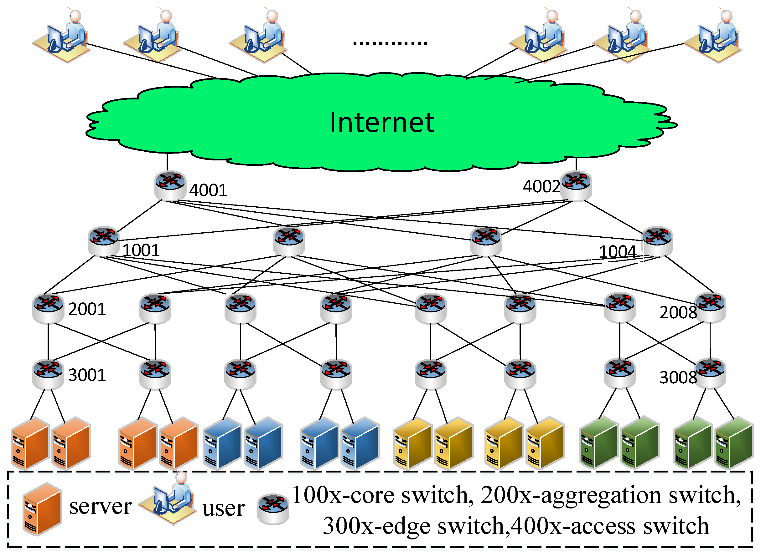
A typical network architecture of a Software Defined Data Center (SDDC) is shown in Figure 1. In that architecture, the service providers often make servers work together to collectively provide service for users. Failures may occur in the switches of Software Defined Data Center Networks (SDDCN) due to the circuit board failures, power failures and error configuration. Meanwhile, failures may also occur in the links due to port failures and network cable problems. Thus, the failure recovery technology is usually used to provide continuous service for users.
For the restoration failure recovery mechanisms, when a failure occurs, the failure detection mechanism will find out that failure and send the relevant information (e.g., location of failure) of that failure to the controller. Then the controller will use the rerouting algorithm to calculate the recovery path based on the failure information and network status. Subsequently, the controller will send some FlowMod messages to the related switches to install or modify flow entries. Then the recovery paths will take effect. After that, the interrupted service will be carried by the recovery paths. In this way, the interrupted service can be recovered from network failures.
The switch failure and link failure are the main failures occur in SDDCN. For the link failure, we can further divide it into two kinds: failure of link between the switch and server and failure of link between switches. For short, the former is referred as the s2e link failure, while the latter is named as the intra-topo link failure in this work. Thus, the network failures that occurred in SDDCNs can be divided into the switch failure, intra-topo link failure and s2e link failure.
So far, a number of solutions regarding failure recovery in SDN have already been proposed [11,12,13,14,15,16,17,18,19,20,21,22,23,24,25,26,27,28,29,30,31,32,33]. Among these mechanisms, 7 mechanisms are protection failure recovery mechanisms [13,14,15,16,17,18,19]. Fourteen mechanisms are restoration failure recovery mechanisms [20,21,22,23,24,25,26,27,28,29,30,31,32,33]. The detailed description of these references are given in Section 2. Generally, the current proposed failure recovery methods are aimed at recovering the faulty switches and faulty links between switches, which means that those methods cannot recover the faulty links between switches and servers. In order to solve the above problem, REVERT is presented to recover all these network failures in SDDCNs. Meanwhile, REVERT can be applied to different network topologies.
1.2. Our Proposal
In order to overcome the above issues, the network failures that occurred in SDDCNs are classified into three types which contain the switch failure, failure of links among switches and failure of links between switches and servers. The problem of recovering the faulty links between switches and servers is proposed. Hence, REVERT is designed. A failure preprocessing method used to classify the network failures, a data structure for storing and finding the affected flows, a server cluster agent for communicating with the server clustering algorithm and a routing path calculation method is proposed to recover the above network failures in SDDCNs, especially the failures of links between the switches and servers are the main components of REVERT.
The essential idea of REVERT is that it first preprocesses and classifies the network failures into the switch failure, intra-topo link failure and s2e link failure. Specifically, for the s2e link failure, it finds out an alternative server to replace the un-reached server. Subsequently, the routing path between the user and that alternative server is calculated and used to translate network traffic.
1.3. Contributions
The contributions of this paper are summarized below.
- Except recovering the switches failures and failures of links between switches, how to recover the failures of links between the switches and servers is also considered in this work.
- The REVERT, which contains a failure preprocessing method, a data structure, a server cluster agent and a routing path calculation method, is proposed to recover network failures in SDDCNs, especially the failures of links between the switches and servers.
- REVERT has been implemented based on the RYU controller. Meanwhile, the performance of REVERT has been evaluated utilizing Mininet, in terms of ability of recovering the above three kinds of network failures, recover time, link utilization and load balance degree.
2. Related Work
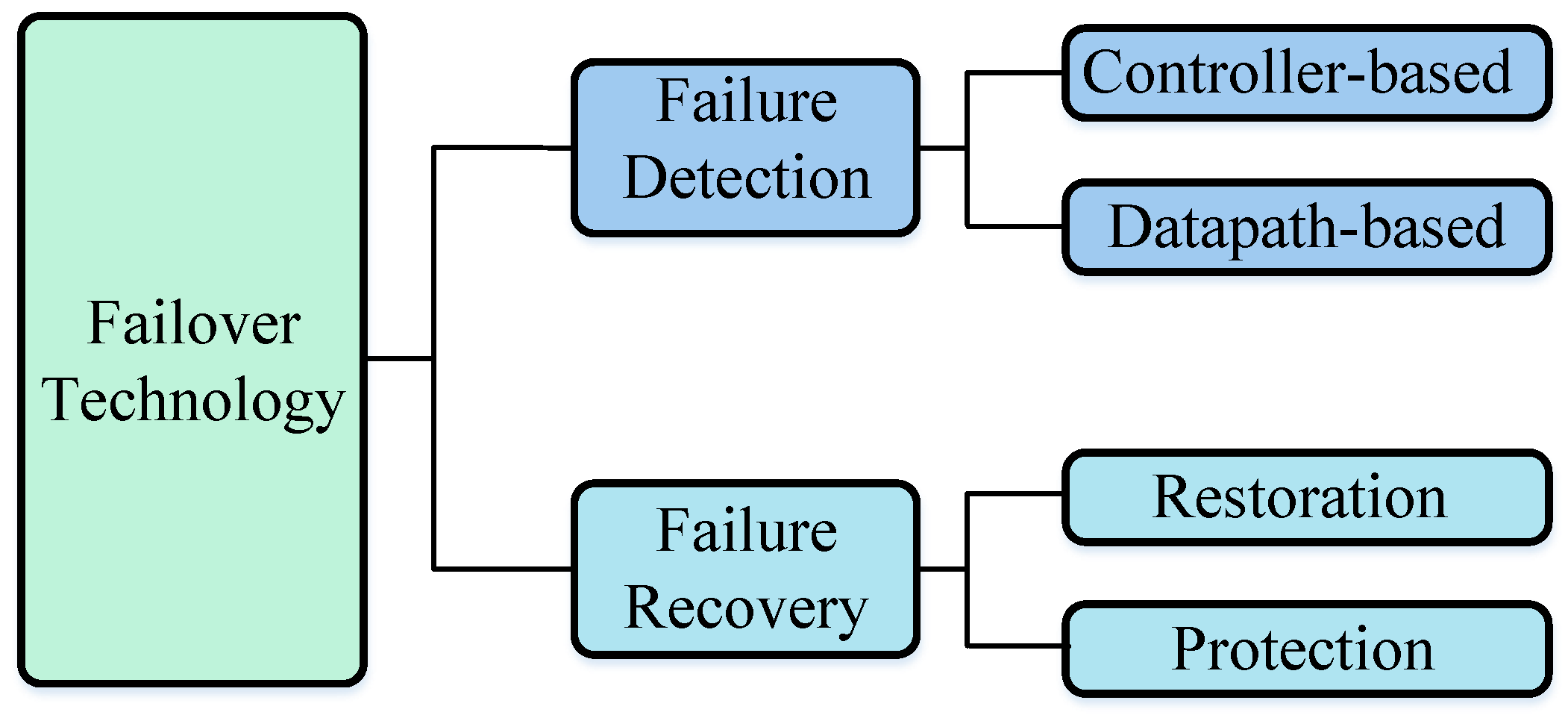
As shown in Figure 2, failure detection and failure recovery technologies are the main parts of failover technology in SDN. Failure detection technology is responsible for detecting failures while the failure recovery technology is responsible for selecting a new path to recover network failures. Failure detection technology includes controller-based failure detection technology and datapath-based failure detection technology. In the controller-based failure detection technology, the controller detects whether a failure occurs in the network. That is usually done by sending special packets (e.g., Link Layer Discovery Protocol (LLDP) packets) from the controller to the underlying network devices. For the datapath-based failure detection technology, Open Shortest Path First (OSPF) protocol and Bidirectional Forwarding Direction (BFD) protocol are usually used to detect failures.
Based on the techniques used in failure recovery, the failure recovery mechanisms in SDN can be classified into restoration failure recovery mechanisms and protection failure recovery mechanisms. For the protection failure recovery mechanisms, the recovery path is constructed in advance. Once a failure occurs, the recovery path will take over. For the restoration failure recovery mechanisms, the recovery path will be calculated by the controller after detecting the network failure. The detailed description of those mechanisms will be given in detail in the following sections.
2.1. Failure Detection
The controller-based and datapath-based failure detection technologies are the main failure detection methods in SDN. The controller-based failure detection technology often uses probe packets to check the connectivity of the underlying network. The datapath-based failure detection technology requires the switch to send some special packets to check the status of network.
In [11], a controller-based failure detection method which is composed of path alive monitoring round and failure location identification round is proposed. In the path alive monitoring round, a monitoring packet is sent from the controller to traverse the monitoring path. If that packet does not return to the controller within a prefix time window, the monitoring path will be regarded as a failure path. Then the failure location identification round starts to find out the location of failure. In this round, the controller sends a special packet to the monitoring path. Once the switch receives this kind of packet, it will forward that packet to the next hop and the controller. If one switch does not send that packet to the controller, the link between this switch and the last switch will be identified as a faulty link.
The datapath-based technology is also widely used [12,13]. In [14], BFD is used to detect failure in SDN. BFD is a protocol used to rapidly detect failure between two network devices. The authors integrate BFD in the stack of OpenFlow enabled switches. Meanwhile, they also expand the OpenFlow protocol to run BFD among switches. When the links or switches are needed to be monitored, the controller will send special messages to the switches. If a switch receives those messages, it will send BFD packets through its local ports. Using BFD, they can quickly find network failures in SDN.
2.2. Failure Recovery
For the protection failure recovery mechanisms [13,14,15,16,17,18,19], the recovery path will be selected in advance. No matter where the recovery path is stored, after the failure is detected, the recovery path will be used to replace the faulty path. Hence, the subsequent arrived packets will be forwarded along the recovery path. In SDN, the recovery path can be stored in the packet headers, group tables or flow entries.
In [15], the path with minimum latency is selected as the primary path. For each hop in the primary path, another path which can avoid link failures along the primary path is chosen as its alternative path. After that, a segment containing the next hop of the primary path, the length of the alternative path and the alternative path will be encoded into the packet header. Meanwhile, a bit field which is used to indicate whether the primary path or the alternative path is taking effect is also encoded in the packet header. If the switch receives a packet, it will check the packet header to get the out port and the type of the working path (primary path or alternative path). Then the switch will find out whether the working path is available. If the primary path is being used and that path is available, the packet will be forwarded through that path. If that path is unavailable, the switch will check whether there is an alternative path. If there is an alternative path, the packet will be forwarded through that path. Otherwise, the packet will be dropped. When the alternative path is in operation, if it is unavailable, the packet will be dropped. Otherwise, the packet will be forwarded through that path.
In [16], the primary path and the alternative path are firstly calculated by the controller. Then a fast-failover group table is installed in the switch. Each entry of that group table contains several action buckets. An action bucket contains a status and some actions associated to that status. The first action bucket of that group table consists of the normal status (means that the primary path is available) and the action that can forward that packet along the primary path. Another action bucket defines the action of forwarding the packet along the alternative path when the first action bucket is unavailable. Thus, when a packet is received, it will be handled according to the first action bucket of the group table. If the primary path is available, that packet will be forwarded along this path. Otherwise, it will be forwarded along the alternative path.
In [17], a path protection recovery mechanism is proposed. For an arbitrary new traffic, the controller firstly calculates a primary path to carry that traffic. Then a backup path is also computed to avoid the failures in the primary path. Subsequently, the primary path and the backup path are installed in the switch using different flow entries. The primary entry has a higher priority than the backup entry to ensure that packets will be forwarded through the primary path when there are no failures. Meanwhile, a module called auto-reject is also installed in the switch. That module is responsible for checking the status of each port of this switch. If any port is identified as unavailable, all flow entries using that port as input port or output port will be deleted. This module guarantees that the backup path will be used to deliver packets when the primary path is broken.
In [18], a backup-resource based failure recovery algorithm is proposed to minimize the consumption of storage resources of switches and meet the required failure recovery delay. In the proposed recovery algorithm, two metrics are firstly used to grade the important level of each link. Then three kinds of strategies for different graded links are used to recover the faulty link. In [19], for the hybrid SDN network, a set of rerouting paths are precomputed based on the column generation technology and Integral Linear Programming (ILP).
At present, some restoration failure recovery mechanisms have already been proposed. In [20], the anchors propose a restoration recovery approach to recover failure in hybrid SDN networks. Tunnels which connect the traditional routers and SDN switches are established beforehand. When a failure happens, the affected packets will be sent to the SDN switches. Subsequently, the SDN controller will make a rerouting path from that SDN switches to the destination. Meanwhile, it can also minimize the maximal link utilization to achieve load balancing and recover the failure. Then some new flow entries will be installed in the switches based on the recovery path calculated by the SDN controller.
In [21], a restoration recovery method is presented. A connectivity matrix table is introduced to store the identifier of switches and its related information (its active ports and the neighbor switches connect to those ports). A local optimal method is proposed to find the recovery path as soon as the failure is detected. When a failure occurs, that method will extract the source switch and destination switch of the failed link and update the connectivity matrix table. Then the path calculator firstly finds whether there is an available path which can recover the failure by inspecting the connectivity matrix table. If the connectivity matrix table has an active entry of that failure, this failure will be treated as recoverable. Then all active entries in the connectivity matrix table are found out and sorted in descending order in terms of traffic load. After that, the least loaded port is chosen as the recovery out port. Subsequently, the FlowMod message (a kind of message used in OpenFlow to add or modify flow entries) is sent to the switch to deploy the recovery path. If the connectivity matrix table does not have an active entry, that failure will be regarded as unrecoverable and the program will terminate.
In [26], the authors show that the problem of computing recovery paths is related to graph search. The modulo strategy, depth-first search strategy and breadth-first search strategy are proposed to calculate the recovery paths. In [31], a restoration recovery mechanism is proposed to recover failures in the data plane of SDN. The authors provide each path a priority. When a failure occurs, the controller chooses the available path with the highest priority as the recovery path. The switchover time and packet loss were measured to evaluate the proposed restoration recovery mechanism. In [32], the operation cost and path cost of recovery are defined and used in the proposed restoration recovery method.
Compared with the protection failure recovery mechanisms, the restoration failure recovery mechanisms need to use the controller to calculate the recovery path when a failure occurs. Meanwhile, the switches in that recovery path need to add or modify those flow entries. Thus, the restoration failure recovery mechanisms will cause more recovery time than the protection failure recovery mechanisms [16,33]. However, the restoration failure recovery mechanisms can achieve some important goals which seem hard to be realized by the protection failure recovery mechanisms. For instance, considering that the backup path is made in advance in the protection failure recovery mechanisms, when several failures occur simultaneously, the backup path may also be affected. In this case, even if there are other available paths which can deliver the affected packets, those packets cannot be forwarded to the destination. On the contrary, as long as a backup path is available, the failure can be recovered using the restoration failure recovery mechanisms. Meanwhile, based on the status of the network, the restoration failure recovery mechanisms can also realize other network functions which cannot be achieved by the protection failure recovery mechanisms. For example, the restoration failure recovery mechanisms can dynamically make a recovery path based on the links state. Thus, it is possible to achieve the network load balancing, Quality of Service (QoS) and other network functions which can not be realized by the protection failure recovery mechanisms.
Therefore, the REVERT, a restoration failure recover method is proposed in this paper. In REVERT, the network failures in SDDCNs are classified into three kinds which contain switch failure, failure of links among switches and failure of links between switches and servers. Then how to recover the failure of links between servers and switches is specially studied. Hence, a failure preprocessing method used to classify the network failures, a data structure for storing and finding the affected flows, a server cluster agent for communicating with the server clustering algorithm, and a routing path calculation method is proposed to recover the above network failures in SDDCNs are proposed.
Main differences between the proposed mechanism and the existing mechanisms are listed in Table 1.
3. REVERT: A Network Failure Recovery Method for SDDCNs
3.1. Detailed Design of REVERT
Table 2 lists the notations used in this paper. Here, we consider an SDDCN topology which contains switches denoted by and servers denoted by . Here, servers and switches are connected by links . E can also be denoted by , where is a intra-topo link set which stands for the set of intra-topo links. Meanwhile, is a s2e link set which contains s2e links. For a request, the link cost of its routing path p is defined as . is the cost of link and it is calculated by , where is the unit price of link and is the bandwidth required by the affected kth request. Meanwhile, the load ratio of link is expressed as . It is denoted by , where is the occupied bandwidth of link and is the total bandwidth of link . Thus, for a request, the load ratio of its routing path p is defined as .
3.1.1. Overall Architecture of REVERT
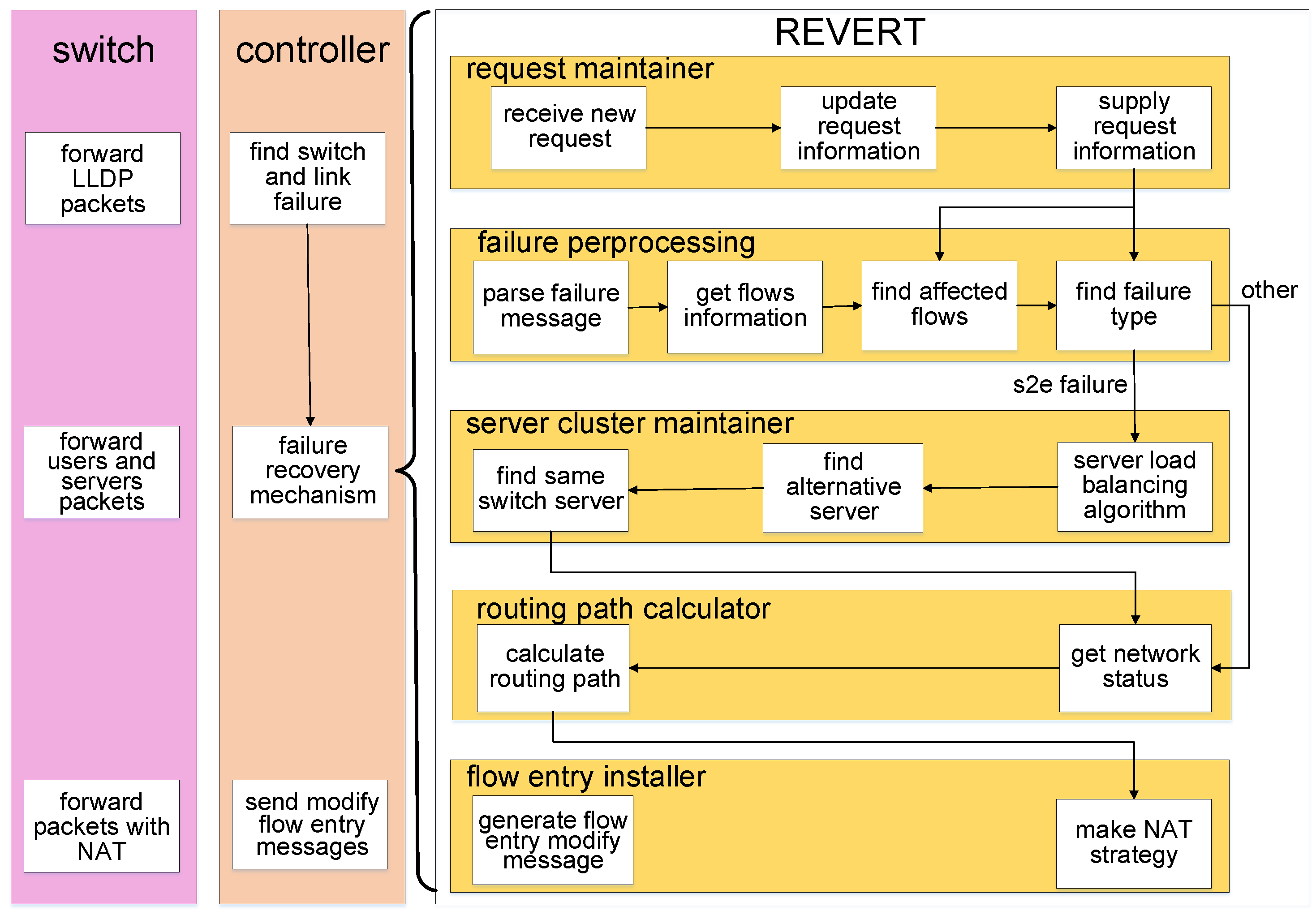
As shown in Figure 3, REVERT consists of five modules, including the failure preprocessing, request maintainer, server cluster maintainer, routing path calculator and flow entry installer. The failure preprocessing is responsible for receiving failure reports from switches, parsing those reports, determining the failure types, finding the affected flows and controlling other modules based on the failure types. The request maintainer stores information of the user, request, destination server and relevant routing path. It provides these information to the failure preprocessing module. The server cluster maintainer is implemented to calculate the alternative server and achieve server load balancing. The routing path calculator uses the routing algorithm to calculate the optimal paths for affected flows. The flow entry installer generates FlowMod messages based on the calculation result of the routing path calculator. Meanwhile, the Network Address Translation (NAT) is also achieved by the flow entry installer.
The detailed description of each module is shown as follows.
Failure preprocessing: When this module receives a failure report from switches, it will first parse the failure report to obtain the location of the network failure. Then the information of all the requests and routing paths will be obtained from the request maintainer. Using those information, the failure preprocessing module finds out all flows affected by the failure. Taking advantages of the whole network topology stored in the SDN controller, it can find out the failure type based on its location. If that failure belongs to the s2e link failure, the server cluster maintainer will be initiated to handle that s2e link failure. Otherwise, the routing path calculator will start to work.
Server cluster maintainer: Several servers often work together to provide same service as a server cluster. Thus, the server cluster maintainer is used to find alternative servers for s2e link failure. If an s2e link failure occurs, the service provided by the related server will be interrupted. Hence, for recovering these failures, another server in the same server cluster which can provide same service as the faulty server will be found out and taken effect to recover the interrupted service. Meanwhile, the server load balancing algorithm is also achieved by this module.
Routing path calculator: The recovery path calculation is achieved in this module. This module periodically gets the status of all links using the port_status_request message (a special kind of message that sent by controller to get the port status of a switch). Once this module starts, the routing algorithm mentioned in Section 3.1.4 will be used to calculate the routing path.
Flow entry installer: This module generates forwarding rules for user requests based on the calculation result made by the routing path calculator and the server cluster maintainer. For the gateway proxy switch, the NAT strategy will be executed on the packets transferred through it. For packets sent from user to server, its source IP and MAC address will be modified to the IP and MAC address of the gateway. Meanwhile, its destination IP and MAC address will be modified to the IP and MAC address of the destination server. For packets sent from server to user, the source IP and MAC address will be modified to the IP and MAC address of the gateway. In addition, the destination IP and MAC address will be modified to the IP and MAC address of the user. For other switches on the routing path, they just forward the arriving packets without modifying those packets.
Request maintainer: When a user first visits the provided service or an flow affected by the network failures is recovered, after the routing paths are made, a relevant message that contains information of the affected flows, including the user, server and routing paths will be stored in this module using the data structure mentioned in Section 3.1.3.
3.1.2. Recovering Network Failures
When a user firstly accesses the service provided by the SDDC, the switch will forward the packets sent from that user to the controller. The controller will choose a server in the server cluster as its destination server and use the routing algorithm to calculate a routing path to carry the traffic between the user and destination server. After the routing path is made, a relevant message that contains information of the user, server and routing path will be stored in the controller. When a failure occurs, the proposed REVERT tries to recover that failure in SDDCNs, which is designed as shown in Algorithm 1.
Once a network failure is detected, an event associated to that failure will be made and sent to REVERT. Then REVERT will first parse the failure event to get the location of that failure (). The flows which are affected by the failure will be found out and recorded as , using the information of all flows including destination address, source address, input port, output port, protocol type and routing path stored in REVERT.
Based on the topology of the underlying network and the parsed failure location, the type of failure can be found out. If it belongs to switch failure or intra-topo link failure , the routing algorithm will be called to calculate a new routing path to recover that failure for each affected flows. Then some flow entries will be installed on the switches based on .
If it is an s2e link failure, for each affected flow, the alternative server that can provide the same service with the affected server will be firstly found out based on the destination IP address of the affected flow, failure location and faulty server . If there is no alternative server, REVERT will stop and send an alert. Otherwise, the routing algorithm will be called to calculate the recovery path for flows between the user and . Then some flow entries will also be installed on the switches of the routing path based on and .
3.1.3. Storing Information and Finding Affected Flows
After the network failure is recovered, the related information of the alternative server and routing path used to recover that failure will be updated. More exactly, a message containing the information of the user, request, alternative server and routing path will be stored in REVERT. Hence, if a failure occurs, those information will be traversed to find all affected flows.
However, if the data structure used to store those information is not well designed, more time will be spent on the query. Even worse, the more users visit the data center, the more time will be wasted on query. For example, for a data center that uses Fat-Tree as its network topology, the routing path for a request will be more than 4 hops. We assume that a data center services m users and each user visits n servers. When a link failure occurs, if a common array or a list is used to store the information, in order to find all affected flows, 4 ∗ m ∗ n times of query will be implemented, which will waste a large amount of time and resources.
| Algorithm 1: Recovering network failures |
| Input: failure message |
Output: recover affected flows
|
In order to solve the above problem, a method designed for storing network information and executing quick query is designed in REVERT, which is shown in Algorithm 2. In order to quickly find the affected flows, and are designed to store the switch related flow and link related flow, respectively. For the switch failure and intra-topo link failure, if an alternative routing path is calculated, it will firstly be parsed to get the information about the user and the destination server . However, for an s2e link failure, the will be obtained from the and alternative server . Subsequently, for each switch in the routing path, if its ID already exists in the keys of , the , and will be appended to . Otherwise, that ID will be made as a new key in and the , and will be made as its value.
| Algorithm 2: Storing information |
| Input: routing path message , alternative server , affected flow |
| Output: store and update related information in , |
|
In addition, for convenience, a link is denoted by , where and are the switches that the link connects. For each link in the routing path, if a link exists in the keys of , the , and will be appended to . Otherwise, will be made as a new key in and the , and will be made as its value.
Taking advantage of this dictionary, when finding the flows affected by the network failure, REVERT only needs to get the failure location. Then it can obtain the information of the affected flows from and . Hence, no matter how many users are served by the data center or which network topology is being used, for finding all affected flows, the query will only be carried out once. In the preceding example, compared with the commonly used methods, this dictionary decreases the time of query from 4 ∗ m ∗ n to 1, which effectively saves time and resources.
3.1.4. Selecting Alternative Routing Paths
For an affected flow, in order to achieve the result that the calculated recovery routing path has low path cost while link load balancing is realized, the fitness of the recovery routing path is defined as . and are the coefficient of the cost and the load ratio , respectively. After that, the problem of calculating recovery path for an affected flow can be formulated as follows.
Minimize:
Subject to:
In order to achieve high network load balancing and low cost, Equation (1) tries to minimize the total load ratio and path cost for the affected flow. Equations (2) and (3) ensure the bandwidth requirement of the kth flow.
In order to solve the above problem, a routing algorithm based on Genetic Algorithm (GA) is used and shown in Algorithm 3. Once the routing algorithm starts, the Depth First Search (DFS) algorithm will be used to choose n paths between the source and destination of the affected flow as the initial population . Each path is called an individual. To satisfy the availability of each individual, each path in must meet the bandwidth of the affected flow and cannot have redundancy loop.
| Algorithm 3: Routing algorithm based on GA. |
| Input:, source address src_ip and destination address dst_ip. |
Output: routing path
|
The fitness of each path is calculated by the function using . In order to save the best individual, the path with maximum fitness is found out and appended to the new population. The Tournament Selection strategy is used to select two paths (for example, ). These two paths will cross at a probability . When cross individuals, the same nodes of that two paths (except the source and destination nodes) are firstly found out. Then one of those same nodes will be chosen as the location of crossover. At last, the two sub-paths of and after that node will be exchanged. Therefore, two new paths and are obtained to form new paths . After crossing paths, there may be redundancy loops in the new paths. In order to remove redundancy loops, the crossed paths are checked and all redundancy loops are removed from .
Subsequently, For each path in , it will mutate at a probability . One node of that path (except the source and destination nodes) is randomly selected as the mutate location. Then the next hop of that node will be mutated to another one and the path from the next hop to the destination node will be calculated by DFS. After that, the mutated path is also checked to remove all redundancy loops. After crossover and mutation, the generated paths will be appended to . Then the selection, crossover and mutation will be executed again until the length of is equal to n.
The selection, crossover and mutation will be executed circularly until the number of iterations () is equal to the predefined value () or the difference between the maximum fitness of current iteration and last iteration () reaches the predefined value ().
4. Evaluation
To validate REVERT, it has been implemented as a module of the RYU controller. In this section, we mainly focus on the evaluation of REVERT. The overall performance of REVERT is evaluated, in terms of the ability of recovering three kinds of network failures, recovery time, link usage and load balancing degree.
4.1. Evaluation Metrics
4.1.1. Recovery Time
When a failure occurs, the failure detection method will spend (the time of finding failures) to find that failure. Then the switch will spend (the time of sending failures) to send a message containing information about the failure to the controller. Upon receiving the message, the controller will firstly spend (the time of finding affected flows) to find all flows affected by that failure. Then the controller begins to recover all affected flows one by one. Assume that there are n affected flows, for the kth affected flow, the controller needs to spend (the time of calculating recovery path) to calculate recovery path p and spend (the time of making a message by a controller) to send FlowMod messages to all switches in that path p. When the switch receives the FlowMod message, it will spend (the time of updating flow entries in switch) to update its flow entries to execute the FlowMod message. Thus, the total recovery time of recovery can be defined as
However, in Equation (4), the length of , and will be affected by the failure detection method, the hardware of the switch and the transmission delay of the path between the switch and controller. Therefore, , and will not be affected by the recovery scheme. Thus, in the evaluation, those parameters are not considered as the main parameters. We mainly measure the total calculation time by using and take it as a major parameter to evaluate REVERT.
4.1.2. Link Usage and Load Balancing Degree
In the evaluation, the path cost and network load balancing were considered as important factors. Therefore, the mean link utilization and the standard deviation of link utilizations are used to evaluate the path cost and load balancing degree (LBD) of the network. Here, LBD is defined as Equation (5):
where n is the number of links in the network. It can be seen that as LBD becomes smaller, better network load balancing can be achieved.
4.2. Simulation Setting
Mininet was used to simulate REVERT. The Fat-Tree topology which contains 22 switches, 16 servers and 100 users was created. All switches in that topology are OpenFlow 1.3 enabled switch. Mininet ran on a computer with a quad core CPU named Intel i5-3470, 4 GB memory, 1 TB hard disk and Ubuntu 14.04 LTS as its operation system. Meanwhile, the RYU controller ran on another computer connected to the computer which runs Mininet. In the simulation, D-ITG was utilized for simulating a large number of requests from different users to the server cluster.
4.3. Evaluation Results
4.3.1. Ability of Recovering Three Kinds of Network Failures
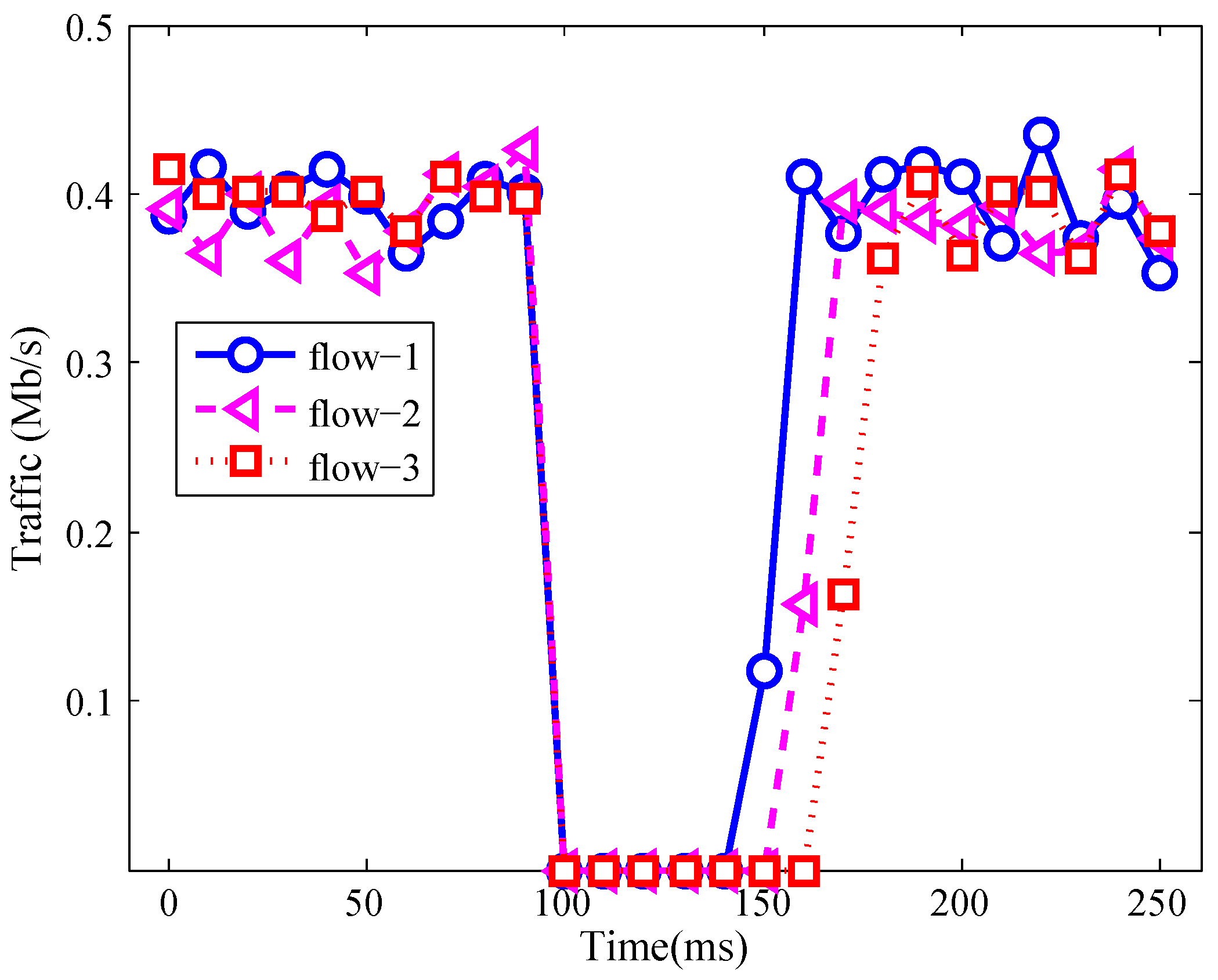
In this evaluation, whether REVERT can recover three kinds of network failures, especially for the s2e link failure was evaluated. In the evaluation, sixteen servers constitute three server clusters. One hundred users randomly access those server clusters via UDP connection. In order to evaluate whether REVERT can recover the s2e link failure, the link between the switch (s3001) and the server (s1) was shut down.
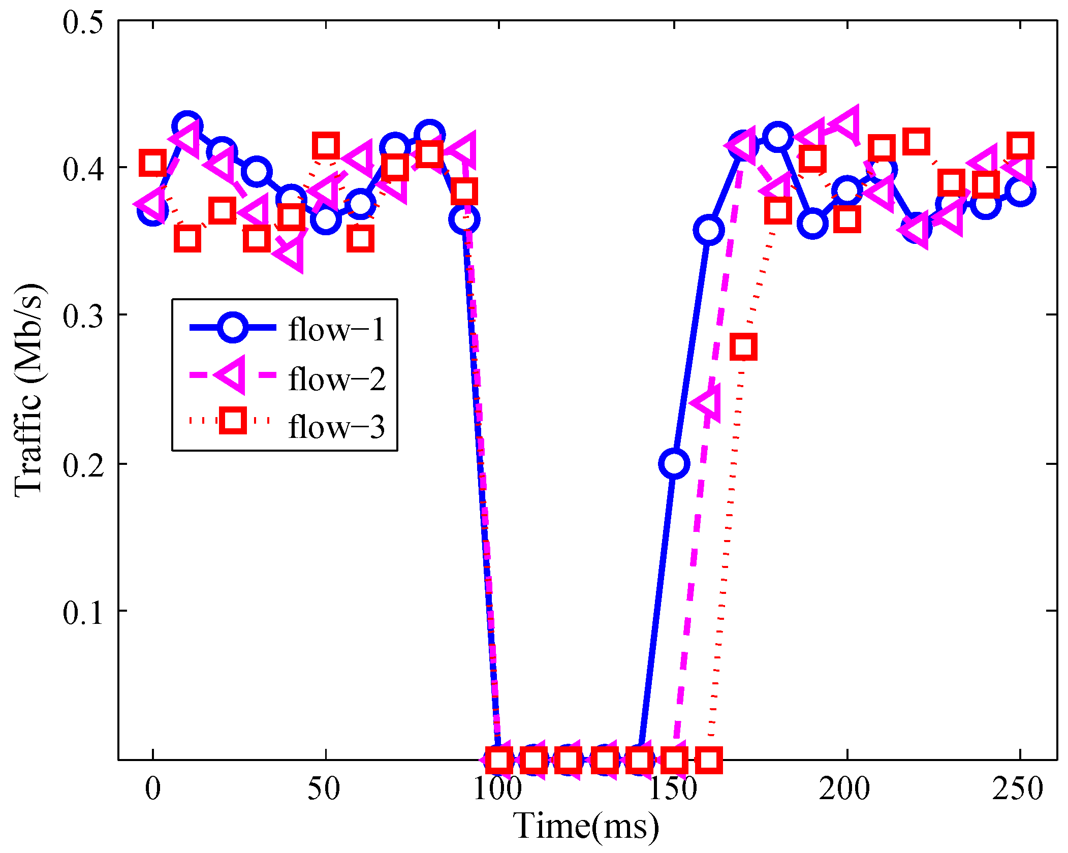
The traffic of three affected flows was measured and shown in Figure 4. In that figure, all affected flows were served by s1 before the s2e link failure occurs. Thus, from 0 ms to 100 ms, the rates of those affected flows were about 400 kb/s. At 100 ms, the link between s3001 and server s1 was shut down. Therefore, the traffic of those three flows was 0. Then the self-healing method started to recover those affected flows. Thus, at 150 ms, the affected flow 1 was recovered and its traffic increased from 0 to about 130 kb/s. Meanwhile, the affected flow 2 and flow 3 were also recovered at 160 ms and 170 ms.
In Figure 4, due to the fact that the affected flow 1, flow 2 and flow 3 were recovered one by one, the traffic of those three flows was recovered one after another. For flow 1, it was recovered at 150 ms. After recovery, the server which provides service for the user was changed from server s1 to server s2. Meanwhile, for flow 2 and flow 3, the chosen recovery servers were server s3 and server s4, respectively.
Table 3 shows the performance comparison of recovering the switch failure, intra-topo link failure and s2e link failure. All the mechanisms listed in that table can recover switch failure and intra-topo link failure. However, except REVERT, all other mechanisms cannot recover s2e link failures. Therefore, the failures in SDDCNs are classified into three kinds and the problem of recovering s2e link failure is introduced in this paper. A self-healing method is presented to recover those three kinds of failures. Thus, REVERT can recover switch failure, intra-topo link failure and s2e link failure.
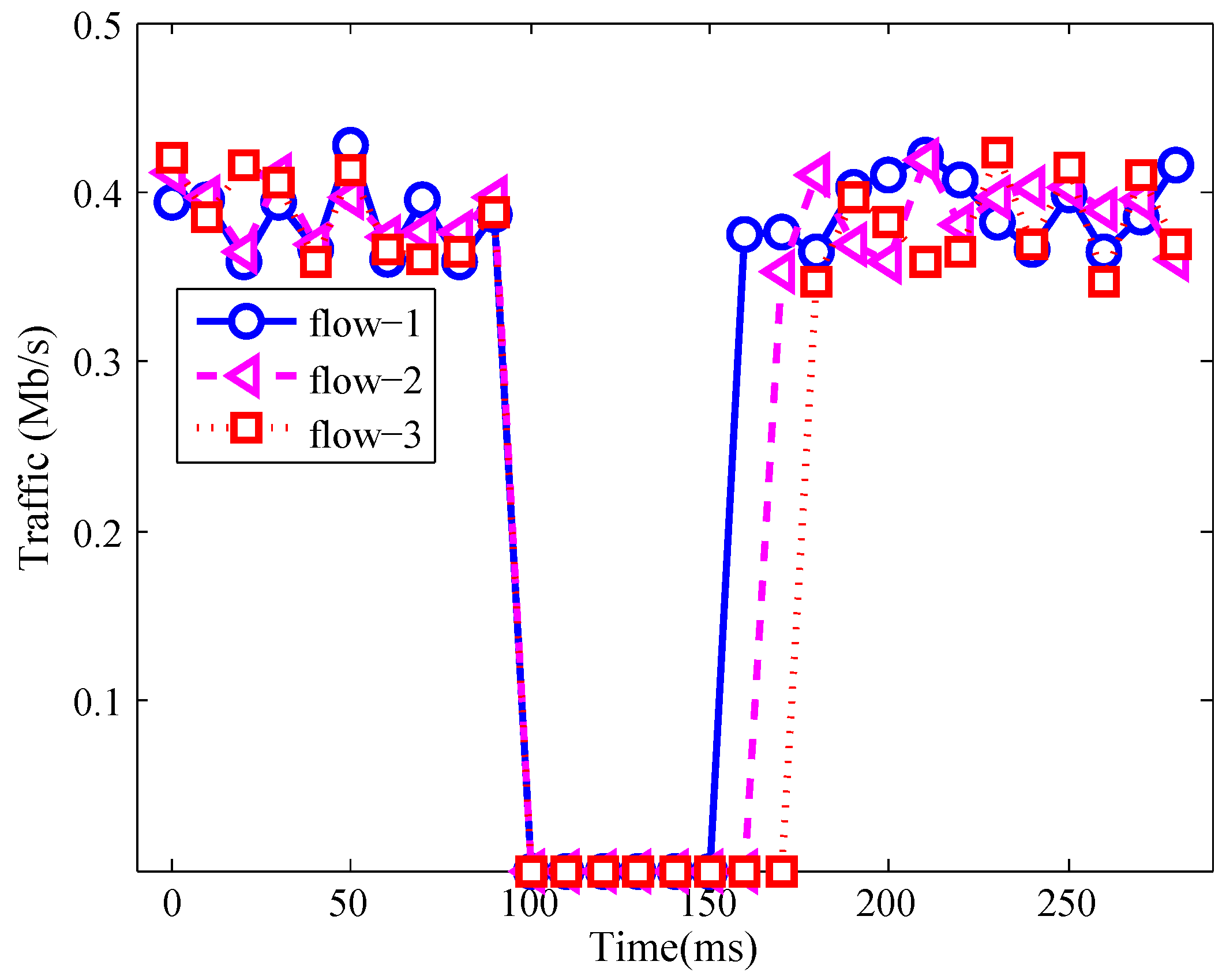
Similarly, Figure 5 and Figure 6 show the traffic during intra-topo link failure and switch failure. In those figures, the affected flows were recovered by REVERT. Thus, those two figures show that REVERT can also recover intra-topo link failure and switch failure.
From the above simulation, we can see that REVERT can successfully recover the s2e link failure, intra-topo link failure and switch failure.
4.3.2. Recover Time
As described in Section 4.1.1, for recovering a network failure, the total recovery time contains the time of detecting failure, calculating recovery path and implementing FlowMod messages. Among those times, the time of detecting failure will be affected by the failure detection method, the hardware of the switch and the transmission delay of the path between the switch and the controller. Meanwhile, the time of implementing FlowMod messages will also be determined by the hardware of the switch. Therefore, the time of detecting failure and implementing FlowMod messages are not the main factor of this mechanism. Hence, in this evaluation, we capture the time of calculating recovery path of the controller to evaluate the performance of the self-healing system more exactly.
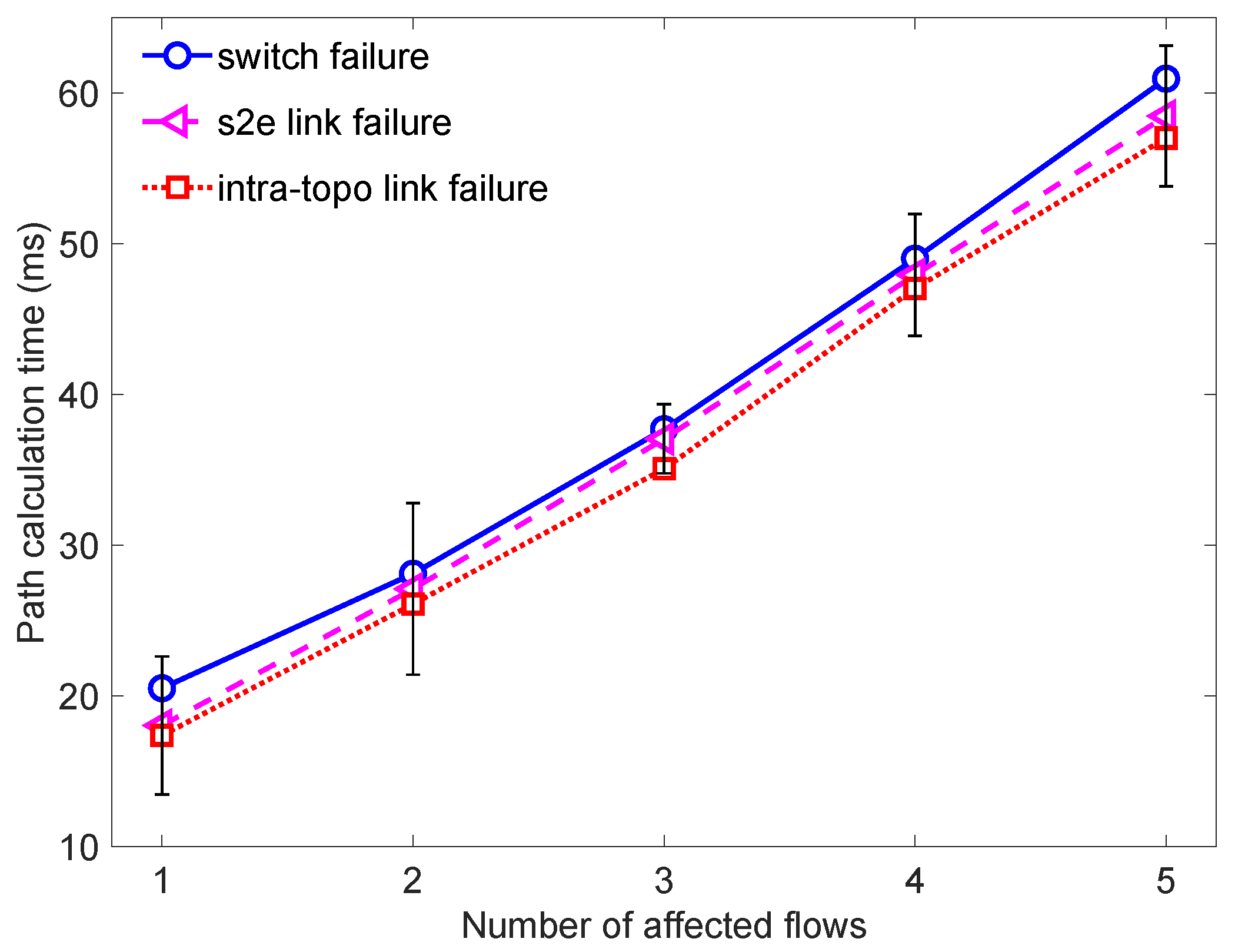
Figure 7 shows the path calculation time for different kinds of failures. In Figure 7, for an affected flow, the mean path calculation time of intra-topo link failure was about 11.4 ms. While for s2e link failure, the calculation time for an affected flow was about 11.7 ms. Meanwhile, for switch failure, it will cost 12.2 ms to recover an affected flow.
From that figure, we can see that the calculating time will increase along with the increase of number of affected flows. The reason is that when a failure is found out, the self-healing method will first find the affected flows. Then the recovery path will be calculated and the FlowMod messages will be sent out to switches. Among that, the time of finding failure is constant in the evaluation. Thus, when the number of affected flows increases, the time of calculating the recovery path and sending FlowMod messages will also increase. Hence, the calculation time will increase with the increasing of the affected flows.
For the switch failure, the calculation time is larger than that of intra-topo link failure and s2e link failure. This is caused by the fact that when a switch failure occurs, the self-healing method will find the faulty links which connect to this faulty switch. Thus, the switch failure will also be treated as link failure. However, comparing with link failure, switch failure will cost more time to find the faulty link. Therefore, the switch failure will cost more time to recover. Meanwhile, due to the fact that comparing with intra-topo link failure, s2e link failure needs to find an alternative server, the calculation time of s2e link failure is larger than intra-topo link failure. Yet, no matter which kind of failure it is, the calculation time will stay in millisecond level.
4.3.3. Link Usage and Load Balance Degree
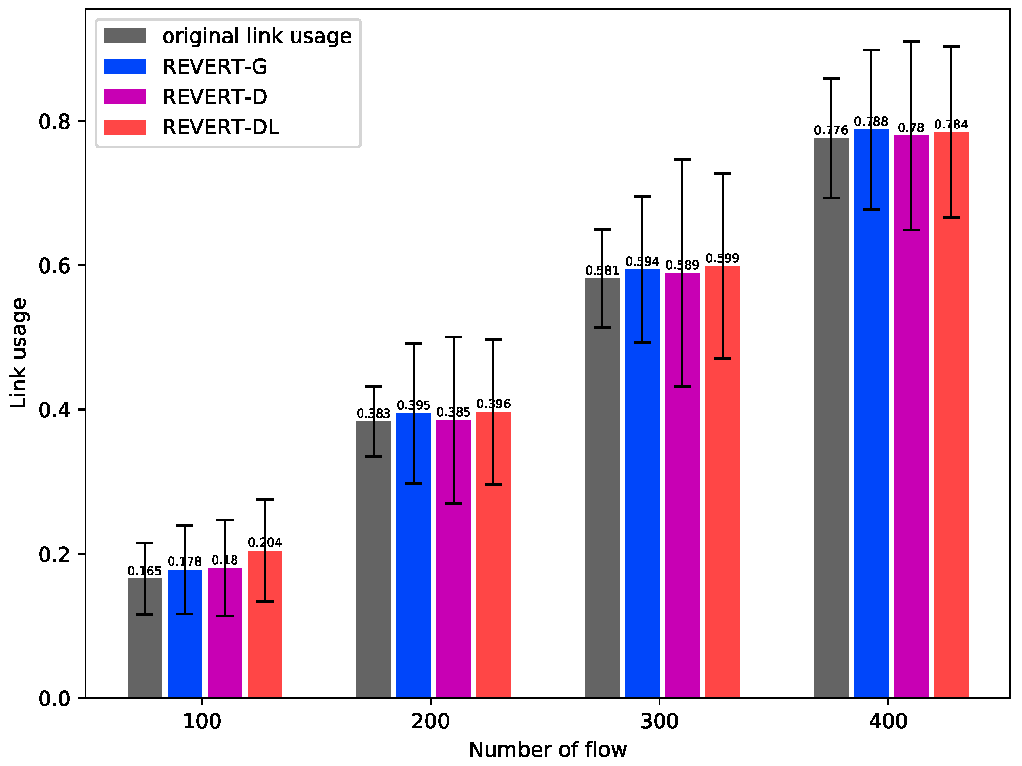
In this evaluation, we try to evaluate the performance when using different routing algorithms. The routing algorithm based on GA algorithm (REVERT-G for short), the routing algorithm which achieves high network load balancing and low link cost based on Dijkstra (REVERT-DL for short) and the routing algorithm used to find the path with minimum link cost based on Dijkstra (REVERT-D for short) were utilized as the routing algorithm in REVERT. The simulation ran with different numbers of requests. The link utilization before the failure was firstly measured. Then after the failure was recovered, the mean link utilization was measured again and its LBD is also calculated.
As shown in Figure 8, for different numbers of flows, after the failure was recovered, the link utilization of REVERT-D is smallest while the link utilization of REVERT-DL is biggest. Meanwhile, after recovering the network failures using REVERT, the link usages are bigger than the original link usages. That is caused by the fact that the hop counts of the rerouting paths are bigger than the original routing path. Especially, when using REVERT-D, the link usages are nearly same with the original link usages. However, REVERT-G and REVERT-DL may cause more link usages than REVERT-D, as shown in Figure 8. The reason is that when using REVERT-G and REVERT-DL to calculate rerouting paths, the LBD is also considered, which makes the hop counts of rerouting paths bigger than REVERT-D. However, no matter which routing algorithm was used in the self-healing method, the mean link utilization was nearly same after recovery. For example, when the number of flows was 300, after recovering failure, the link utilization of REVERT-G, REVERT-D and REVERT-DL were 0.594, 0.589 and 0.599, respectively. Thus, from this evaluation, we can see that the differences of link utilization of REVERT-G, REVERT-D and REVERT-DL are small.
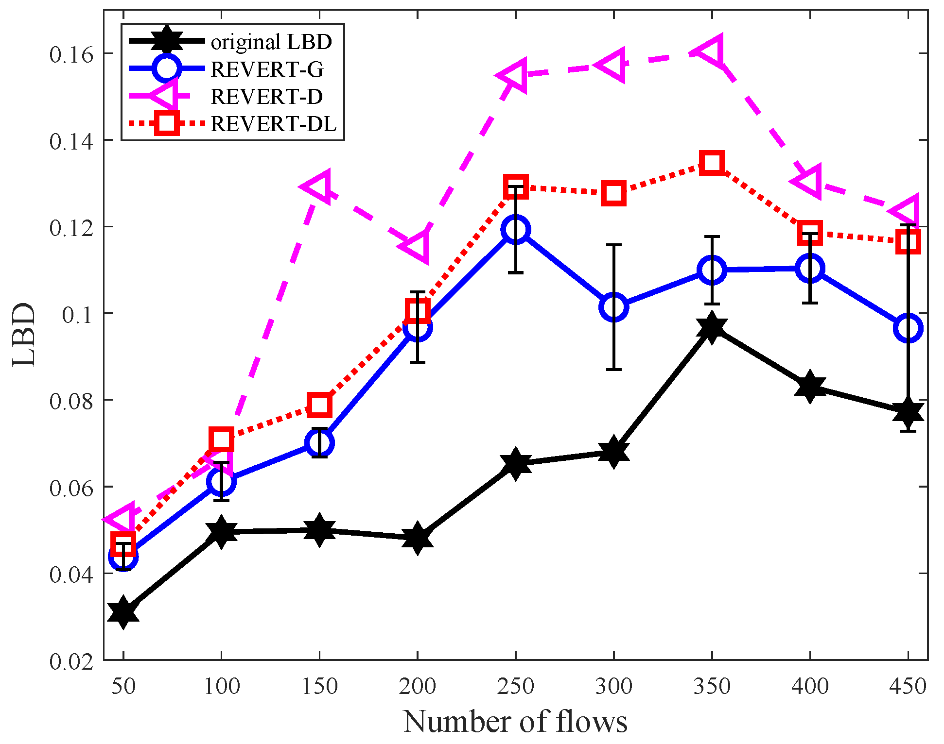
Figure 9 shows the changes of LBD when using different routing algorithms. In Figure 9, the star markers stand for the LBD before failure. The roundness markers, triangle markers and square markers represent for the calculated LBD of REVERT-G, REVERT-D and REVERT-DL after recovering failure. In Figure 9, when the number of flows increased from 50 to 350, the four LBD curves also increased. However, when the number of flows was bigger than 400, the LBDs started to decrease. This is because when the network load is high (about above 80% in this case), every link will be assigned a number of traffic to carry. This means that the link utilizations of every link will be high. Thus, the LBD of those three routing algorithms will be nearly the same.
For the three routing algorithms, the LBD of REVERT-G is smaller than that of REVERT-D and REVERT-DL after recovery. Meanwhile, the LBD of REVERT-D is biggest. For example, when the number of flows was about 300, the LBD of REVERT-G, REVERT-D and REVERT-DL were 0.1014, 0.1573 and 0.1277, respectively. It shows that the REVERT-G can achieve better load balancing performance than REVERT-D and REVERT-DL.
5. Conclusions
In this paper, the failures of SDDCNs are classified into three kinds which contain switch failure, intra-topo link failure and s2e link failure. Then the problem of recovering s2e link failure is proposed. Subsequently, the REVERT used to recover all kinds of failures in SDDCNs is proposed and demonstrated. REVERT has been implemented as a module of the RYU controller. Some evaluation metrics including the ability of recovering all these kinds of network failures, recovery time, link usage and load balance degree are stated and measured to evaluate REVERT. The mean path calculation time for one traffic affected the s2e link failure is about 18.04ms. Although the mean link usages increase after recovering the network failures, the increased value is slight and acceptable. For instance, when there are more than 200 flows in the network, the mean link usages only slightly increases by about 1.83 percent. According to the evaluation results, REVERT can recover switch failure, intra-topo link failure and s2e link failure successfully.
Author Contributions
Conceptualization, Y.C.; Formal analysis, Y.C.; Investigation, Y.C.; Methodology, Y.C. and Q.Q.; Writing–original draft, Y.C.; Writing–review and editing, Q.Q., G.S., C.G. and S.L. All authors have read and agreed to the published version of the manuscript.
Funding
This work was supported by the National Key Research and Development Program of China under Grant No. 2019YFB1803500, National Natural Science Foundation of China (NSFC) under the Grant No. 61902085, Fundamental Research Funds for the Central Universities under the Grant No. 2682019CX63, Guizhou Provincial Science and Technology Plan under the Grant No. [2020]1Y267, and Scientific Research Foundation for Introduced Talents of Guizhou University under the Grant No. (2019)52.
Conflicts of Interest
The authors declare no conflict of interest.
References
- Di, S.; Kondo, D.; Cappello, F. Characterizing cloud applications on a Google data center. In Proceedings of the 2013 42nd International Conference on Parallel Processing, Lyon, France, 1–4 October 2013; pp. 468–473. [Google Scholar]
- Dehury, C.K.; Sahoo, P.K. Failure Aware Semi-Centralized Virtual Network Embedding in Cloud Computing Fat-Tree Data Center Networks. IEEE Trans. Cloud Comput. 2020. [Google Scholar] [CrossRef]
- Marahatta, A.; Wang, Y.; Zhang, F.; Kumar, A.; Tyagi, S.K.S.; Liu, Z. Energy-Aware Fault-Tolerant Dynamic Task Scheduling Scheme for Virtualized Cloud Data Centers. Mob. Netw. Appl. 2019, 24, 1063–1077. [Google Scholar] [CrossRef]
- Zhang, M.; Mysore, R.N.; Supittayapornpong, S.; Govindan, R. Understanding lifecycle management complexity of datacenter topologies. In Proceedings of the 16th USENIX Symposium on Networked Systems Design and Implementation (NSDI ’19), Boston, MA, USA, 26–28 February 2019; pp. 235–254. [Google Scholar]
- Sun, G.; Zhou, R.; Sun, J.; Yu, H.; Vasilakos, A.V. Energy-efficient provisioning for service function chains to support delay-sensitive applications in network function virtualization. IEEE Internet Things J. 2020, 7, 6116–6131. [Google Scholar] [CrossRef]
- Wang, S.; Bi, J.; Wu, J.; Vasilakos, A.V.; Fan, Q. VNE-TD: A virtual network embedding algorithm based on temporal-difference learning. Comput. Netw. 2019, 161, 251–263. [Google Scholar] [CrossRef]
- Tank, G.P.; Dixit, A.; Vellanki, A.; Annapurna, D. Software-Defined Networking: The New Norm for Networks. Available online: https://www.opennetworking.org/images/stories/downloads/sdn-resources/white-papers/wp-sdn-newnorm.pdf (accessed on 27 May 2020).
- Bao, X.; Liang, H.; Liu, Y.; Zhang, F. A Stochastic Game Approach for Collaborative Beamforming in SDN-Based Energy Harvesting Wireless Sensor Networks. IEEE Internet Things J. 2019, 6, 9583–9595. [Google Scholar] [CrossRef]
- Jain, S.; Kumar, A.; Mandal, S.; Ong, J.; Poutievski, L.; Singh, A.; Venkata, S.; Wanderer, J.; Zhou, J.; Zhu, M.; et al. B4: Experience with a globally-deployed software defined WAN. ACM SIGCOMM Comput. Commun. Rev. 2013, 43, 3–14. [Google Scholar] [CrossRef]
- Cui, Y.; Yan, L.; Li, S.; Xing, H.; Pan, W.; Zhu, Z.; Zheng, X. SD-Anti-DDoS: Fast and efficient DDoS defense in software-defined networks. J. Netw. Comput. Appl. 2016, 68, 65–79. [Google Scholar] [CrossRef]
- Lee, S.S.W.; Li, K.Y.; Chan, K.Y.; Lai, G.H.; Chung, Y.C. Path layout planning and software based fast failure detection in survivable OpenFlow networks. In Proceedings of the 2014 10th International Conference on the Design of Reliable Communication Networks (DRCN), Ghent, Belgium, 1–3 April 2014; pp. 1–8. [Google Scholar]
- Rehman, A.U.; Aguiar, R.L.; Barraca, J.P. Fault-Tolerance in the Scope of Software-Defined Networking (SDN). IEEE Access 2019, 7, 124474–124490. [Google Scholar] [CrossRef]
- Feng, S.X.; Wang, Y.; Zhong, X.X.; Zong, J.R.; Qiu, X.S.; Guo, S.Y. A Ring-based Single-link Failure Recovery Approach in SDN Data Plane. In Proceedings of the 2018 IEEE/IFIP Network Operations and Management Symposium (NOMS 2018), Taipei, Taiwan, 23–27 April 2018; pp. 1–8. [Google Scholar]
- Sharma, S.; Staessens, D.; Colle, D.; Pickavet, M.; Demeester, P. In-band control, queuing, and failure recovery functionalities for OpenFlow. IEEE Netw. 2016, 30, 106–112. [Google Scholar] [CrossRef] [Green Version]
- Ramos, R.M.; Martinello, M.; Rothenberg, C.E. Slickflow: Resilient source routing in data center networks unlocked by openflow. In Proceedings of the 38th Annual IEEE Conference on Local Computer Networks ((LCN), Sydney, Australia, 21–24 October 2013; pp. 606–613. [Google Scholar]
- Sharma, S.; Staessens, D.; Colle, D.; Pickavet, M.; Demeester, P. OpenFlow: Meeting carrier-grade recovery requirements. Comput. Commun. 2013, 36, 656–665. [Google Scholar] [CrossRef]
- Sgambelluri, A.; Giorgetti, A.; Cugini, F.; Paolucci, F.; Castoldi, P. OpenFlow-based segment protection in Ethernet networks. J. Opt. Commun. Netw. 2013, 5, 1066–1075. [Google Scholar] [CrossRef]
- Zhang, S.; Wang, Y.; He, Q.; Yu, J.; Guo, S. Backup-resource based failure recovery approach in SDN data plane. In Proceedings of the 2016 18th Asia-Pacific Network Operations and Management Symposium (APNOMS), Kanazawa, Japan, 5–7 October 2016; pp. 1–6. [Google Scholar]
- Tomassilli, A.; Di Lena, G.; Giroire, F.; Tahiri, I.; Saucez, D.; Perennes, S.; Turletti, T.; Sadykov, R.; Vanderbeck, F.; Lac, C. Poster: Design of survivable SDN/NFV-enabled networks with bandwidth-optimal failure recovery. In Proceedings of the 2019 IFIP Networking Conference (IFIP Networking), Warsaw, Poland, 20–22 May 2019. [Google Scholar]
- Chu, C.Y.; Xi, K.; Luo, M.; Jonathan Chao, H. Congestion-aware single link failure recovery in hybrid SDN networks. In Proceedings of the 2015 IEEE Conference on Computer Communications (INFOCOM), Hong Kong, China, 26 April–1 May 2015; pp. 1086–1094. [Google Scholar]
- Li, J.; Hyun, J.H.; Yoo, J.H.; Baik, S.; Won-Ki Hong, J. Scalable failover method for data center networks using OpenFlow. In Proceedings of the 2014 IEEE Network Operations and Management Symposium (NOMS), Krakow, Poland, 5–9 May 2014; pp. 1–6. [Google Scholar]
- Kempf, J.; Bellagamba, E.; Kern, A.; Jocha, G.; Takacs, A.; Sköldström, P. Scalable fault management for OpenFlow. In Proceedings of the 2012 IEEE International Conference on Communications (ICC), Ottawa, ON, Canada, 10–15 June 2012; pp. 6606–6610. [Google Scholar]
- Van Adrichem, N.L.M.; van Asten, B.J.; Kuipers, F.A. Fast recovery in software-defined networks. In Proceedings of the 2014 Third European Workshop on Software Defined Networks, Budapest, Hungary, 1–3 September 2014; pp. 61–66. [Google Scholar]
- Achleitner, S.; Bartolini, N.; He, T.; La Porta, T.; Tootaghaj, D.Z. Fast Network Configuration in Software Defined Networking. IEEE Trans. Netw. Serv. Manag. 2018, 15, 1249–1263. [Google Scholar] [CrossRef]
- Xu, A.; Bi, J.; Zhang, B.; Xu, T.; Wu, J. USTR: A High-Performance Traffic Engineering Approach for the Failed Link. In Proceedings of the 2018 IEEE 38th International Conference on Distributed Computing Systems (ICDCS), Vienna, Austria, 2–6 July 2018; pp. 1–8. [Google Scholar]
- Borokhovich, M.; Schiff, L.; Schmid, S. Provable data plane connectivity with local fast failover: Introducing openflow graph algorithms. In Proceedings of the 3rd Workshop Hot Topics Software Defined Networking (HotSDN), Chicago, IL, USA, 22 August 2014; pp. 121–126. [Google Scholar]
- Geng, H.; Yao, J.; Zhang, Y. Single Failure Routing Protection Algorithm in the Hybrid SDN Network. Comput. Mater. Contin. 2020, 64, 665–679. [Google Scholar] [CrossRef]
- Nguyen, K.; Minh, Q.T.; Yamada, S. A software-defined networking approach for disaster-resilient WANs. In Proceedings of the 2013 22nd International Conference on Computer Communication and Networks (ICCCN), Nassau, Bahamas, 30 July–2 August 2013; pp. 1–5. [Google Scholar]
- Kim, H.; Schlansker, M.; Santos, J.R.; Tourrilhes, J.; Turner, Y.; Feamster, N. Coronet: Fault tolerance for software defined networks. In Proceedings of the 2012 20th IEEE International Conference on Network Protocols (ICNP), Austin, TX, USA, 30 October–2 November 2012; pp. 1–2. [Google Scholar]
- Kitsuwan, N.; Slyne, F.; McGettrick, S.; Payne, D.; Ruffini, M. A Europe-wide demonstration of fast network restoration with OpenFlow. IEICE Commun. Express 2014, 3, 275–280. [Google Scholar] [CrossRef] [Green Version]
- Sharma, S.; Staessens, D.; Colle, D.; Pickavet, M.; Demeester, P. Enabling fast failure recovery in OpenFlow networks. In Proceedings of the 2011 8th International Workshop on the Design of Reliable Communication Networks (DRCN), Krakow, Poland, 10–12 October 2011; pp. 164–171. [Google Scholar]
- Astaneh, S.A.; Heydari, S.S. Optimization of SDN flow operations in multi-failure restoration scenarios. IEEE Tran. Netw. Serv. Manag. 2016, 13, 421–432. [Google Scholar] [CrossRef]
- Sharma, S.; Staessens, D.; Colle, D.; Pickavet, M.; Demeester, P. Fast failure recovery for in-band OpenFlow networks. In Proceedings of the 2013 9th International Conference on the Design of Reliable Communication Networks (DRCN), Budapest, Hungary, 4–7 March 2013; pp. 52–59. [Google Scholar]
Figure 1.
A typical network architecture of Software Defined Data Center (SDDC).

Figure 2.
Classification of failover technology in data plane of Software-Defined Networking (SDN).

Figure 3.
Overall architecture of REVERT.

Figure 4.
Traffic during s2e link failure.

Figure 5.
Traffic during intra-topo link failure.

Figure 6.
Traffic during switch failure.

Figure 7.
Path calculation time of different failures.

Figure 8.
Comparison of link usage.

Figure 9.
Comparison of load balancing degree.


Table 1.
Brief analysis of REVERT and the existing mechanisms.
| Reference | Type | Technique | Application Scenarios | Contribution | Limitation |
|---|---|---|---|---|---|
| [19] | Protection | ILP; column generation | hybrid SDN network | It precomputes a set of rerouting paths while satisfies the service function chain requirements. | When recovering the network failures, the current network traffic statistics information is not considered. |
| [20] | Restoration | heuristic algorithm; optimization problem; rerouting | hybrid SDN network | It can recover network failures in hybrid SDN networks, by reroute the traffic on the failed link through rerouting paths. | It needs to periodically calculate rerouting paths, no matter whether a link failure occurs. |
| [21] | Restoration | connectivity matrix table; local optimal method; uplink and downlink separation | SDN network | It can recover the network failure using a connectivity matrix table and a local optimal method, where the port has least load will be chosen as the recover out port. | A static value has been chosen to collect the traffic statistic information. When calculating the rerouting path, only the traffic load is considered. |
| [26] | Restoration | modulo strategy; DFS; BFS | SDN network | It provides modulo strategy, DFS- and BFS-based routing algorithms used to recover the network failure. | No implementation and evaluation have been given in this work. |
| [27] | Restoration | 0-1 ILP; greedy algorithm | hybrid SDN network | Network failures are recovered by forwarding the affected packets to SDN switches. | The load balance is not considered when calculating rerouting paths. |
| This paper | Restoration | failure preprocess; failure classify; server cluster | SDN network | Except recovering the switch failure and failure of link between switches, it can also recover the failures of links between the switches and servers. | It is designed for SDN network, which means that it can not work in hybrid SDN network. |
Table 2.
Notations used in the paper.
| Notations | Definition |
|---|---|
| G | Network topology |
| V | A set of switches |
| E | A set of links |
| S | A set of servers |
| The ith switch | |
| The link between node and | |
| The ith server | |
| A set of links among switches | |
| A set of links connect switches and servers | |
| The cost of link | |
| The unit price of link | |
| The bandwidth required by the affected kth request | |
| The load rate of link | |
| The currently used bandwidth of link | |
| The total bandwidth of link |
© 2020 by the authors. Licensee MDPI, Basel, Switzerland. This article is an open access article distributed under the terms and conditions of the Creative Commons Attribution (CC BY) license (http://creativecommons.org/licenses/by/4.0/).
Share and Cite
MDPI and ACS Style
Cui, Y.; Qian, Q.; Shen, G.; Guo, C.; Li, S. REVERT: A Network Failure Recovery Method for Data Center Networks. Electronics 2020, 9, 1187. https://doi.org/10.3390/electronics9081187
AMA Style
Cui Y, Qian Q, Shen G, Guo C, Li S. REVERT: A Network Failure Recovery Method for Data Center Networks. Electronics. 2020; 9(8):1187. https://doi.org/10.3390/electronics9081187
Chicago/Turabian StyleCui, Yunhe, Qing Qian, Guowei Shen, Chun Guo, and Saifei Li. 2020. "REVERT: A Network Failure Recovery Method for Data Center Networks" Electronics 9, no. 8: 1187. https://doi.org/10.3390/electronics9081187
Note that from the first issue of 2016, this journal uses article numbers instead of page numbers. See further details here.