Article

Emergency Mechanical Ventilator Design: Low-Cost and Accessible Components

1
Ingeniería Industrial, Facultad de Ingeniería y Ciencias Aplicadas, Universidad de las Américas, Quito 170125, Ecuador
2
Ingeniería en Diseño Industria, Facultad de Ingeniería y Ciencias Aplicadas, Universidad Central del Ecuador, Quito 170146, Ecuador
3
Faculty of Engineering and Applied Sciences (FICA), Telecommunications Engineering, Universidad de Las Américas (UDLA), Quito 170124, Ecuador
4
Facultad de Ciencias Médicas, Universidad Central del Ecuador, Quito 170129, Ecuador
5
Doctorado en Dirección de Proyectos, Universidad de Investigación e Innovación de México, Morelos 50550, Mexico
6
Instituto de Automática (INAUT), Universidad Nacional de San Juan-CONICET, San Juan J5400ARL, Argentina
7
Facultad de Tecnologías de Información, Universidad Latina de Costa Rica, San José 11501, Costa Rica
*
Author to whom correspondence should be addressed.
Electronics 2022, 11(23), 3910; https://doi.org/10.3390/electronics11233910
Submission received: 27 October 2022 / Revised: 10 November 2022 / Accepted: 10 November 2022 / Published: 26 November 2022
(This article belongs to the Special Issue Emerging Electronic Technologies for Biomedical Applications)

Abstract

:
This paper presents the fundamentals; criteria; and mechanical, electrical, and electronic aspects required to properly operate and control emerging mechanical ventilators. We present the basis for their design and manufacture as a contribution to implementing this type of equipment at low cost for intensive care units. In particular, we describe the materials and the mechanical, electrical, and electronic aspects used to implement the SURKAN mechanical ventilator, which was developed in Ecuador during the COVID-19 pandemic for some health centers in the country. The proposed mechanical ventilator provides a functional and reliable design that can be considered a reference for future developments and new implementations.

1. Introduction

Due to the unsatisfied demand for mechanical ventilation equipment in intensive care units, many organizations worldwide have developed and produced mechanical ventilators with regional technology [1,2,3,4,5,6] due to the closing of borders caused by the COVID-19 pandemic.
Mechanical ventilators are moderate–high-risk level III devices [7] because they allow medications, bodily fluids, or other substances to be removed from the patient and provide respiratory support to patients with dyspnea. Their functions require proper measurement and control of minimum parameters such as airway pressure, inhalation flow, expiratory flow, and oxygen level of the gas provided [8], guaranteeing that the patient is subjected to respiratory conditions without harming their body. A mechanical ventilator has the following subsystems: input (pneumatic and electrical), energy conversion and transmission (external compressor and pneumatic valves), and control scheme (circuits, variables, and control stages) [9]. When the parameters exceed the established limits, the output will show flow graphs, pressure, and alarms as warnings. When the parameters exceed the conventional limits, the output will permanently activate alarms, and the flow and stress can be monitored by employing real-time graphs.
Mechanical ventilation was first developed in the 1800s [10] using rustic equipment that lacked control systems. The development of electronics allowed the evolution of this equipment, especially in terms of accuracy and performance for medical use. In the years after 1940, mechanical ventilation equipment was innovated, and improvements were implemented in later versions [11]; new functionalities and modes of operation were implemented to provide invasive and non-invasive ventilation more efficiently to patients in multiple scenarios. As a result, there are three types of mechanical ventilators: manual ventilators [12], portable ventilators [13], and intensive care ventilators [14].
Today, the fourth generation of Intensive Care Unit (ICU) ventilators is characterized by using microprocessors that synchronize intermittent mechanical ventilation (SIMV). Some companies around the world have incorporated 16 modes of operation into their equipment [15]; all methods employ a pneumatic system with proportional opening and closing valves and can be controlled with the help of sensors and algorithms that allow the operation, controlling, and monitoring of some respiratory parameters and ventilation modes [16].
Considering the compressed gas pressure source, there are two types of ventilators. The first type uses an insufflation bag, and the other is connected to medicinal air and oxygen networks. Both types provide air volume to patients suffering from respiratory failure [17]. Otherwise, for mechanical ventilators that work with an insufflation bag, multiple configurations, as presented in [18], require different motors and torques to drive the mechanisms that compress the insufflation pockets and provide pressure or air/oxygen volume mix to the patient.
Mechanical ventilators that use air and oxygen from hospital networks are the most commonly used in intensive care units because they employ sensors that detect if the patients intend to breathe and assist them with adequate respiratory support. This type of equipment is more complex in construction and costly [19,20]. With the increasing use of information technologies, ventilators have been developed with the possibility of remote communication and information management involving migration to databases and decision support. It is even possible to monitor the patient’s condition by identifying exhaled volatile organic compounds [11].
This work presents the criteria and aspects for designing and implementing a mechanical ventilator. In particular, we describe the materials and the mechanical, electrical, and electronic aspects used to implement the SURKAN mechanical ventilator of Ecuadorian origin, which was developed during the COVID-19 pandemic and is currently used in some health centers in the country.
The rest of the paper is organized as follows: Section 2 presents the methodology employed. Section 3 describes the materials used for implementation. Section 4 describes the design process. Section 5 presents the results and some discussions. Finally, Section 6 summarizes the main conclusions of this work.

2. Methods

The design of mechanical ventilators must consider mechanical, electronic, electrical, and control interface aspects to provide adequate functionality to the equipment, as shown in Figure 1.
An adequate ventilator operation considers the minimum required aspects such as intelligent alarm systems and a closed-loop control system that regulates figurative elements such as pressure and volume, guaranteeing adequate support for ventilation [11].
An electronic scheme is also required to generate a versatile printed circuit board (PCB) to enable coupling of the electronic components. Some boards are being developed to implement mechanical ventilators, such as those presented in [7,8]. In addition, electronic sensors should measure the flow in the inhalation and expiratory lines, airway pressure, and the level of oxygen delivered to the patient [18].
Due to the COVID-19 pandemic, multiple mechanical ventilators have been developed and conceived locally to support the medical system in health institutions [21]. Some emerging developments present easily constructed and reproducible designs, while others are characterized by low-cost technologies and open-source applications [22] with easy-to-obtain components. Among all the alternatives presented in the literature, the SURKAN mechanical ventilator, of Ecuadorian origin, is characterized by its high performance, configuration methods, friendly environment, and the possibility of remote configuration to provide dynamic support. Thus, it ensures a rapid response to the high demand of patients who require mechanical ventilation for health emergencies [23].

3. Materials

This section presents some considerations for selecting materials for properly implementing mechanical ventilators.

3.1. Materials for the Equipment

There are guidelines for medical equipment that establish requirements such as safety, quality, sustainability [24], design, and construction, in addition to considerations about the toxicity and compatibility of the materials used with biological tissues, cells, and body fluids [25,26,27].
Medical-grade materials demonstrate high resistance to the use of many disinfectants and cleaning agents available on the market. Raw material suppliers provide basic test results and can be used as initial selection criteria. It is essential to evaluate the behavior of materials under the corresponding working conditions (temperature, concentration, and time) [28].

3.2. Materials for the Components

This section deals with the mechanical aspects of the fan’s external structure and the components’ support. As for the electrical and electronic system, the recommended material is the insulator for its correct operation, avoiding the influence of static electric fields.

3.3. Structural Materials

The structure shall support the weight of the components without deformations that may affect the functionality of the assembly and its components. One of the primary features of medical equipment is that it does not generate contaminants or residues and must be machined for removable joint assembly for the sake of maintainability. Due to the considerable weight of the ventilator, in the range of 24–50 pounds, a metal plate greater than 1.0 mm provides appropriate rigidity for equipment that does not exceed volumes of 400 mm × 400 mm × 300 mm. Sheet metal is a common option for this equipment as it does not corrode in contact with air; is of medical grade; and allows sterilization by autoclave, ethylene oxide, and radiation [29].
The use of surface treatment can help provide aesthetic character and sufficient protection against organic solvents used during cleaning [30]. The materials that meet the above characteristics are martensitic and austenitic stainless steels, grade 1–4 commercial titanium, and cobalt superalloys with high and low carbon content. Stainless steel can be used as a lower-cost alternative [31].

3.4. Insulation of Electrical and Electronic Systems

To attenuate the effect of electric, magnetic, and electromagnetic fields generated in the control circuits and prevent them from emitting radiation and causing electromagnetic interference (EMI) in other adjacent systems, such as the monitored screen and actuators, the effect of a Faraday cage must be reproduced, keeping electromagnetic waves within the zone of influence. Shielding can be achieved by minimizing the signal passing through the system, either by wave reflection or absorption and dissipation of radiation within the material [32]. The effectiveness of EMI shielding (SE) is expressed in decibels (dB); 30 dB corresponds to 99.9% attenuation of EMI radiation and is considered a suitable shield for many applications. Metals have shielding because they allow the Faraday cage effect [33].
Materials that maximize the Faraday cage effect are conductive materials, generating the effect in a wide range of electromagnetic frequencies, high magnetic permeability, high absorption coefficient, low reflectivity, and low specific weight [34]. The selected material must not have a thickness that unnecessarily compromises the total weight of the equipment; for this purpose, it is recommended that the construction employs a thickness between 0.8 mm and 1.2 mm and does not have grooves that allow the output of EMI [33]. Hence, using a magnetic shield in order to not reflect the waves and generate an additional effect is recommended. In this type of shielding, magnetic materials can be used instead of materials with good conductivity, which increases permeability, but decreases conductivity. If a magnetic material is used, care must be taken in the machining process, as it could change its magnetic properties, and care must be taken not to reach magnetic saturation [35]. Magnetic materials are more effective at low frequencies (below 10 kHz) than materials with good electrical conductivity, such as copper. Steel is better than copper in the case of 1 kHz electromagnetic fields. At 1 MHz, copper is better than steel [36]. Table 1 summarizes the properties of some metals that can be used as EMI attenuators.

3.5. Airway Equipment
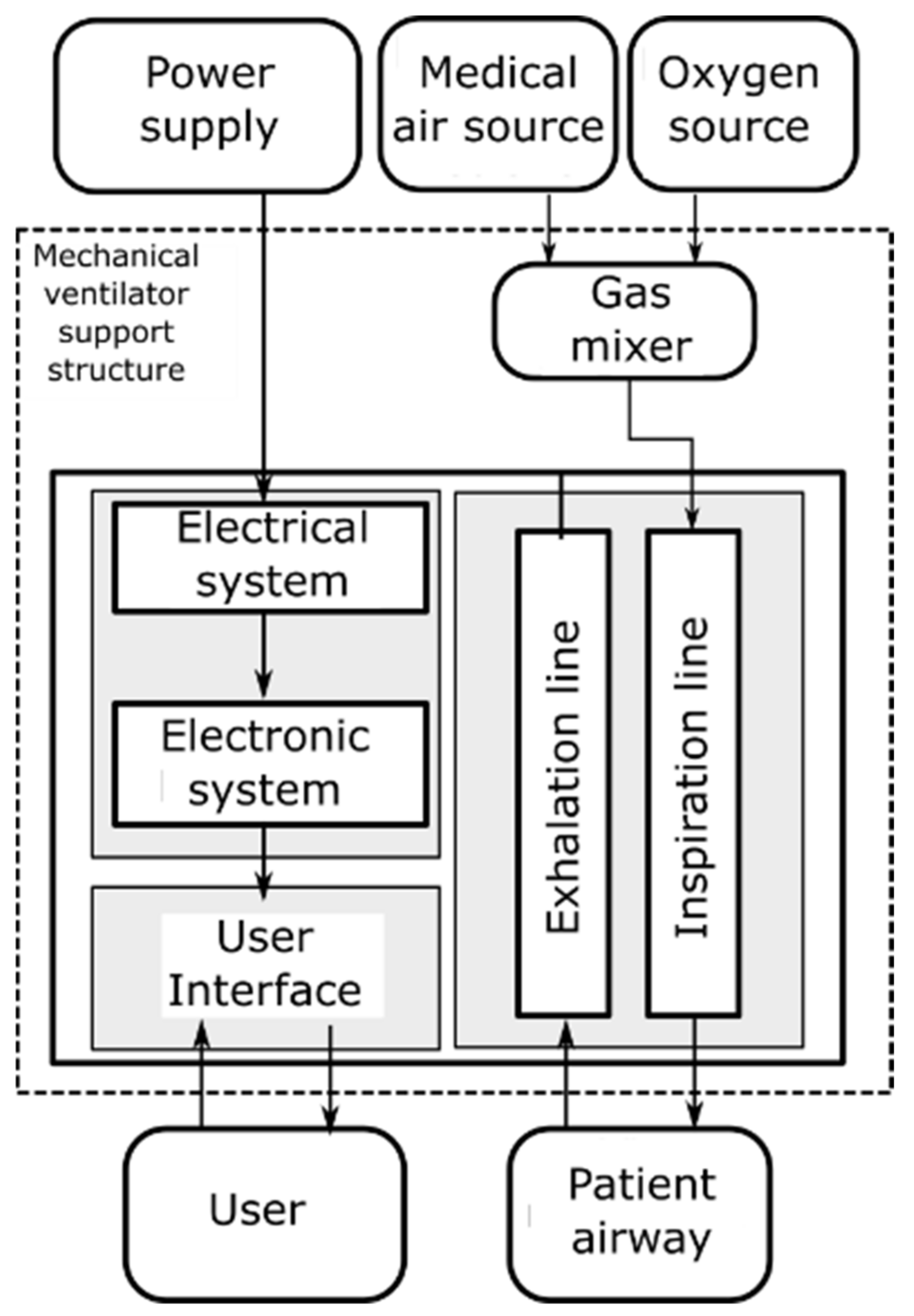
The gas flow path to the patient begins after a mixer delivers the amount of medical air and oxygen in the proportions specified by the user. The mixed gas flows through an air pipe into an inhalation mouth, passes into the patient’s circuit, and then returns through an inspiration mouth; eventually, the fluid will pass through a filter before returning to the environment.
The ducts, valves, sensors, and joints used must not generate contaminants, residues, or oxides during their operation and contact with the air. If possible, ducts should conform to the set couplings and diameters used in commercial patient circuit kits, which have a diameter of 0.75 inches, to facilitate coupling and replacement of parts.
Inspiratory and expiratory wells must be manufactured using a machinable material and not generate residues or oxides in contact with the gas. They must be chemically inert and of medical grade according to ISO 10993. The materials of this component must additionally withstand sterilization processes such as radiation [37], ethylene oxide [38], and autoclave sterilization [39], as well as cleaning agents such as organic solvents [40]. The internal pressure of the gas should not exceed 0.05 bar, and although it is low, fatigue due to cyclic changes in internal pressure stresses should be considered in the design. At the same time, the external dimensions of the person’s mouth should have minimum external pressure. According to the above, the materials that can be selected for their manufacture are martensitic and semi-austenitic stainless steels, surgical steel, grade 1–4 titanium, tungsten of considerable commercial purity, and cobalt superalloys. In the case of series production, polymers such as ethylene-vinyl acetate (EVA) with a Shore hardness greater than 85 and nylon PA66 can be used.
Due to their frequency of use and importance, the valves must have a high resistance to fatigue, wear, and oxidation [41]. In addition, they must not generate residues during their operation [42] and must be of medical grade according to ISO 10993. Thus, materials that could be used are [43] austenitic stainless steel, martensitic stainless steel, cobalt-based superalloys, commercial-grade gold, nickel–chromium alloys, commercial-grade silver, and molybdenum alloy tool steel (AISI M42). An emergent ventilator design for use in pandemic situations should consider criteria, values, and reference characteristics for the appropriate selection of components in the following aspects.

4. Design

The following details the ventilator implementation’s mechanical, electrical, and electronic aspects.

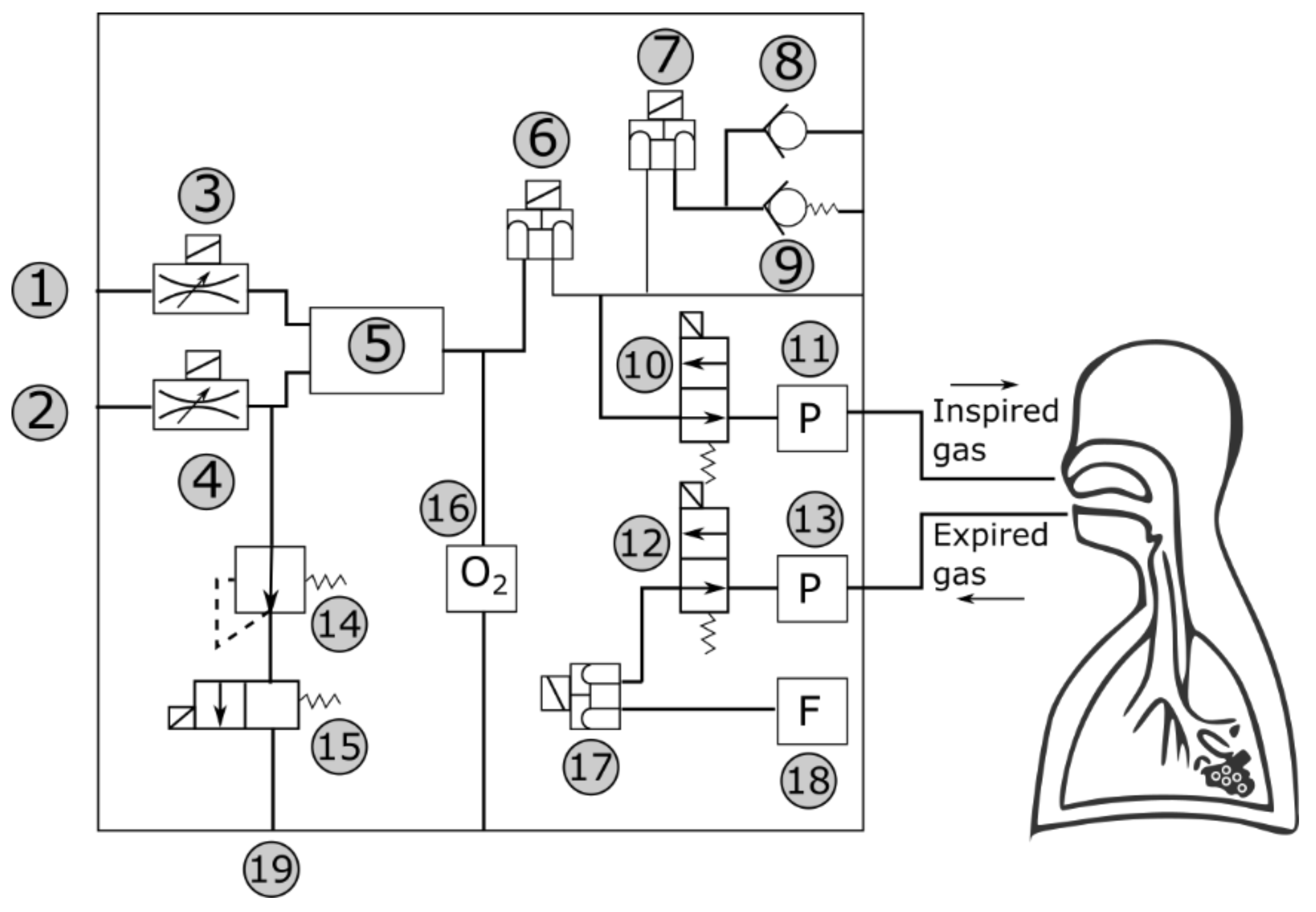
4.1. Mechanical Aspects

This subsection explains the indispensable components for the design of mechanical ventilation equipment that requires using a source of oxygen, medical air, and an alternating current of 110 VAC.
Figure 2 shows a diagram detailing the parts and fundamental components for the design of mechanical ventilators for ICUs. This figure shows three well-defined parts: the electrical power supply, medicinal air, and oxygen source. The second part corresponds to the components housed inside the support structure of the mechanical ventilator, and finally, the outputs of the equipment, which are the user interface and the inhalation and exhalation outputs.
According to [16], a mechanical ventilator needs approximately one liter per minute with a supply pressure of 2–4 bar to provide the necessary pressure to ventilate the lungs, taking most of the oxygen obtained from the medicinal air and regulating the oxygen source to obtain the appropriate mixture for a given case [44]. The gas mixer equipment is represented in Figure 2, which is the stage where the gases are mixed.
Exhalation and inhalation lines control these flows; the latter is fed by the gas mixer that receives oxygen and air. Airborne ducts have a diameter of 0.75 inches and are adaptable to components for manual ventilators [12].
A mobile base for transporting the mechanical ventilator is indispensable because patient turnover is high in the intensive care unit and movement of equipment is inevitable.

4.2. Electrical and Electronic Aspects

Mechanical ventilators have a set of electrical and electronic elements that must be chosen appropriately for their effective operation and stability [23]. This subsection describes the considerations and characteristics of the minimum electrical and electronic components essential for achieving a ventilator for ICU use. These devices have the following parts: programming panel, electrical system, pneumatic systems, power system, gas supply system, patient circuit, and alarm system. Appropriate operation is achieved by calibration [45].

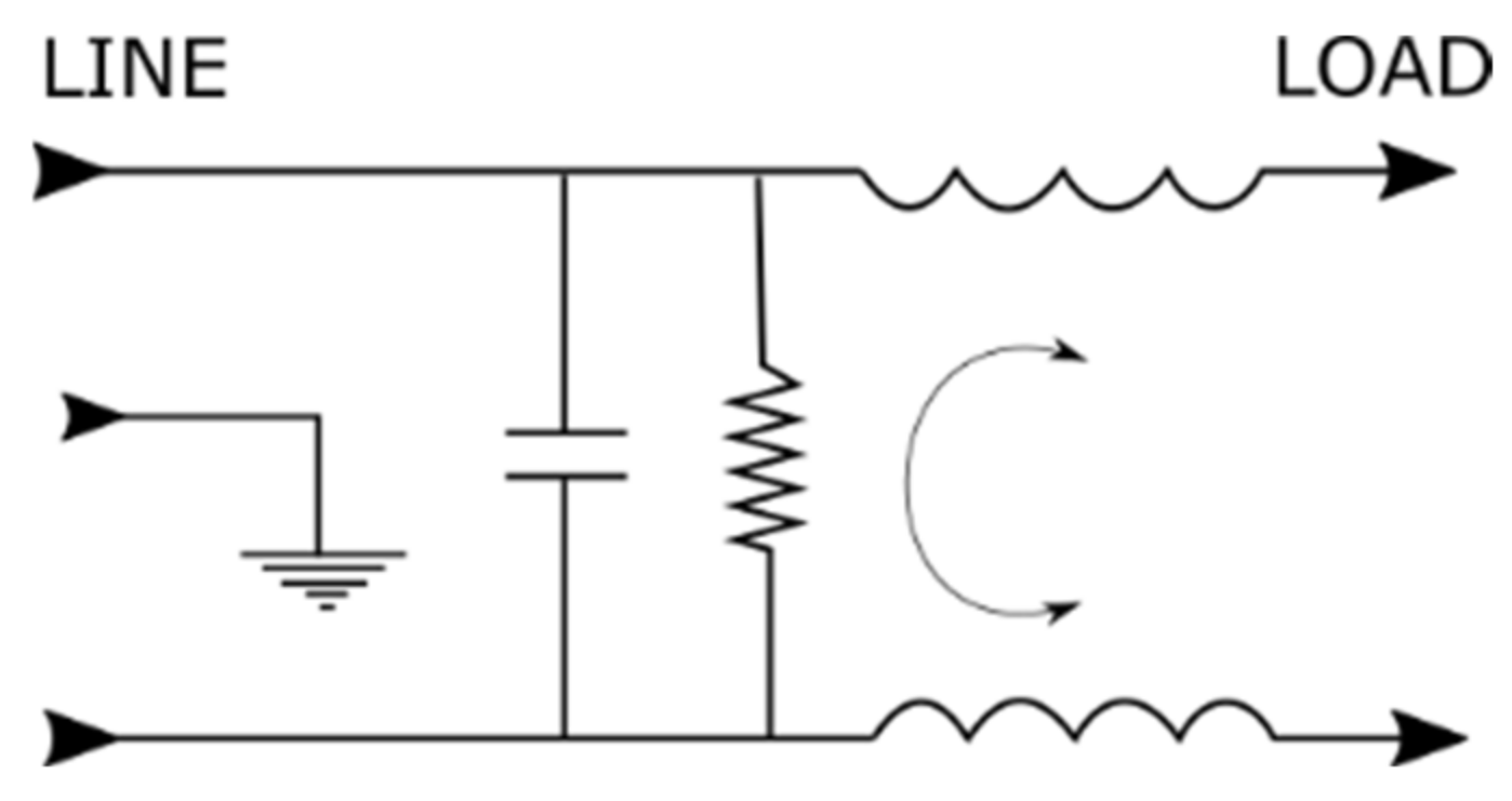
4.2.1. Electrical Design

In the electrical design of newly emerging mechanical ventilators, the effect of fluctuations and distortions in the electrical network, the power of the elements used, the power of the necessary source, and—given the nature of the emerging equipment—the use of easily accessible elements should also be considered.
According to [11], a proper mechanical ventilator design must ensure that the equipment continues operation despite power interruptions in the hospital’s power supply. IEC 60601-1 third edition [16] states that this equipment must have an internal battery and be connected to an uninterruptible power supply (UPS) or the hospital power generator. Many devices developed after the pandemic emergency use an external UPS, allowing them to operate autonomously for at least 20 min [8]. This UPS will be sized based on the amount of power required by the system. An excellent reference is a 1000 VA and 480 W UPS, as suggested in [7].
Due to some electronic devices’ complexity, fluctuating and distorted current consumptions and high-frequency noise are produced, which must be eliminated by incorporating filters with suitable designs to withstand fluctuations [15]. The noise affects medical equipment, which needs to be energized through the electrical grid isolated to other conventional devices [46].
Mechanical ventilators must meet several standards depending on the country where they are developed, for instance, the third edition of IEC 60601-1, the international standard of general requirements for the basic safety and essential performance of medical electrical equipment in the United States [16]. To meet these requirements, mechanical ventilation requires electromagnetic interference (EMI) filters that prevent power fluctuations from entering the equipment and have minimal leakage current to reduce the risk of electric shock to the patient [14]. The medical filters used in some applications correspond to the description of PS00XDH3A [19] (Figure 3), which adequately protects medical equipment. The low quality of electrical power supplied to mechanical ventilators makes it necessary to use an EMI filter at the inlet of the equipment; these filters must comply with the norm IEC 60321-1 C14 and be of medical grade. Some alternatives, such as the PS00XDH3A filters [47], have been used in developments such as those described in [1,7,9]. The characteristics of this filter are inductance of L = 2 × 2.0 mH, capacitance of C = 0.047 uF, and resistance of R = 3.3 MΩ.
Figure 3 shows an electrical schematic of the PS00XDH3A filter, which can serve as the basis for local manufacturing if it cannot be purchased. It is an RLC filter of EMI type, supporting a current up to 3 A, an IEC voltage of 120 VAC, and a UL voltage of 250 VAC, primarily used for medical applications.
In a mechanical ventilator, many components must be energized using a direct current source, which is energized by alternating current [23]. The power of the elements in direct current (DC) must be considered to select the source. Table 2 presents the indispensable components of a ventilator developed in [16].
In compliance with the standards presented in [16], the recommended power supply must be of medical grade and allow the conversion of current from 110–240 V AC to 12 V DC while complying with the means of protection (MOP) established by IEC 60321-1 C14. The power supplies used for this equipment are of the closed-closed switching type for AC/DC voltage with low leakage current between 100 μA and 450 μA. These power supplies must be selected according to the energy consumption of the equipment elements (whose reference values are presented in Table 2) and considering a safety factor of 25%. For the example in Table 2, a 63.125 W power supply has been determined. Therefore, an output of 12 VDC and 7A is required [44]. The efficiency of these power supplies currently reaches values close to 89%.

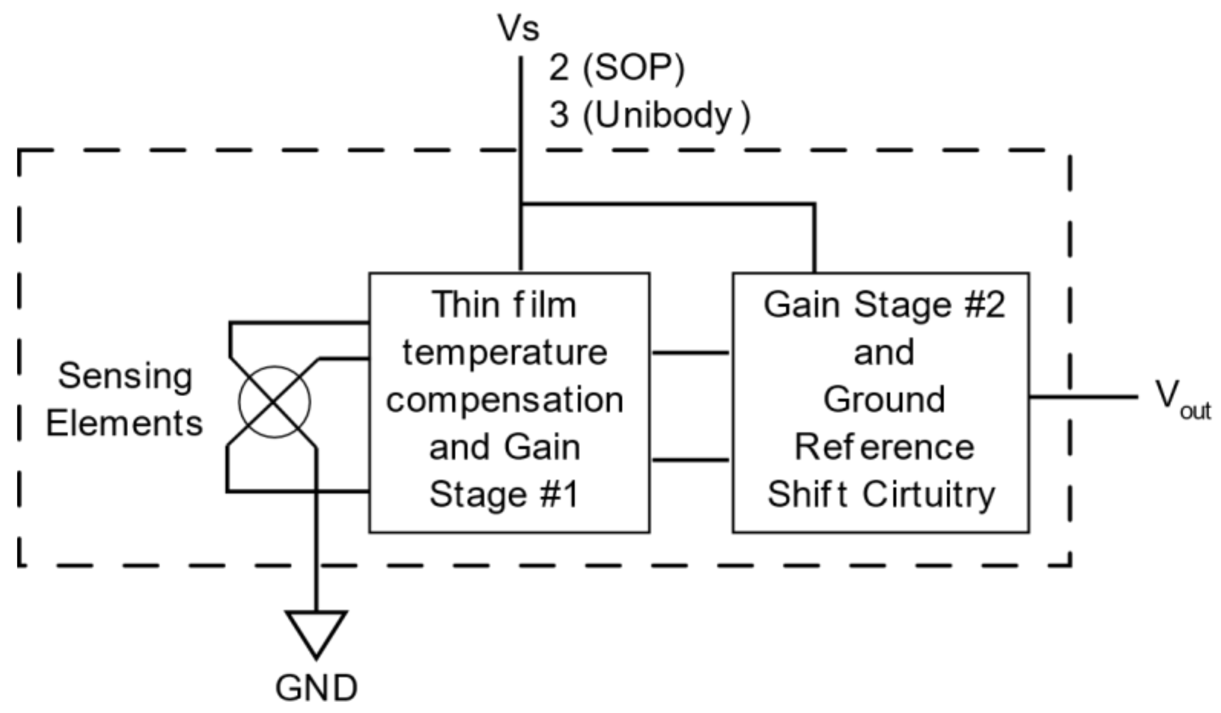
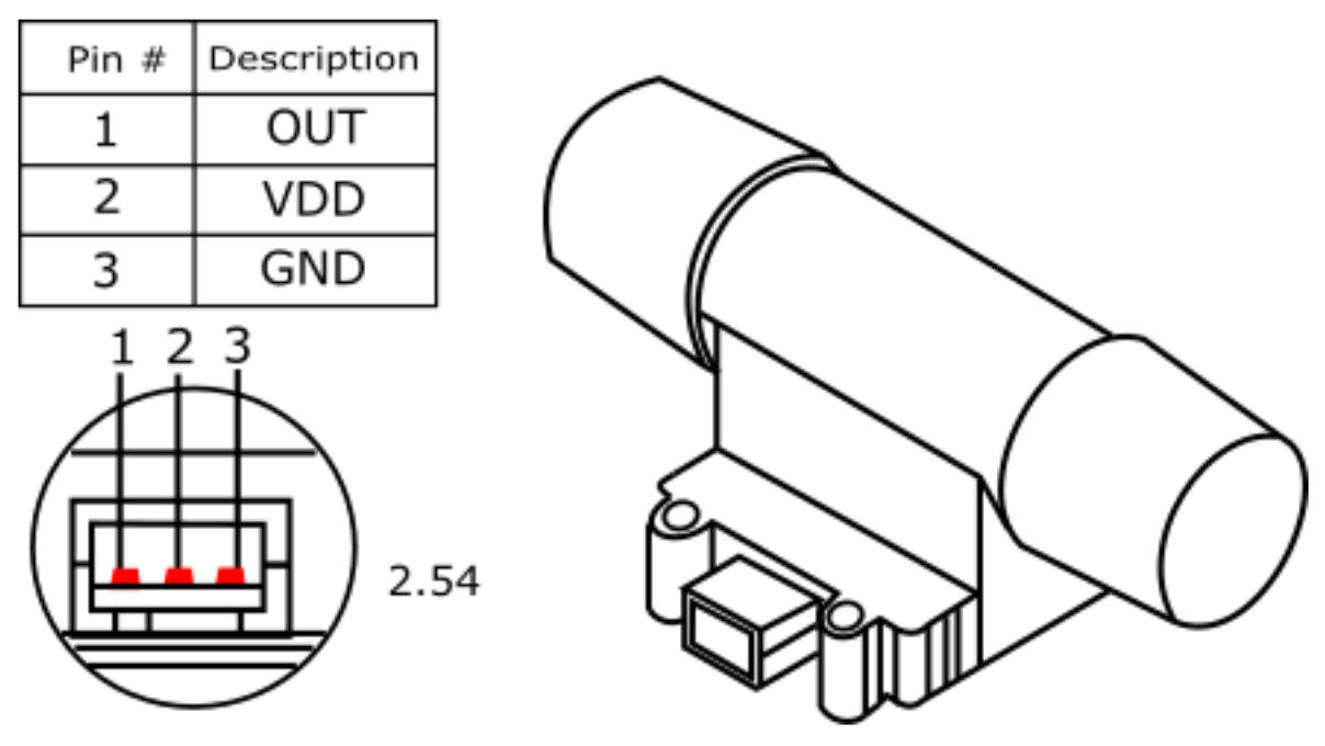
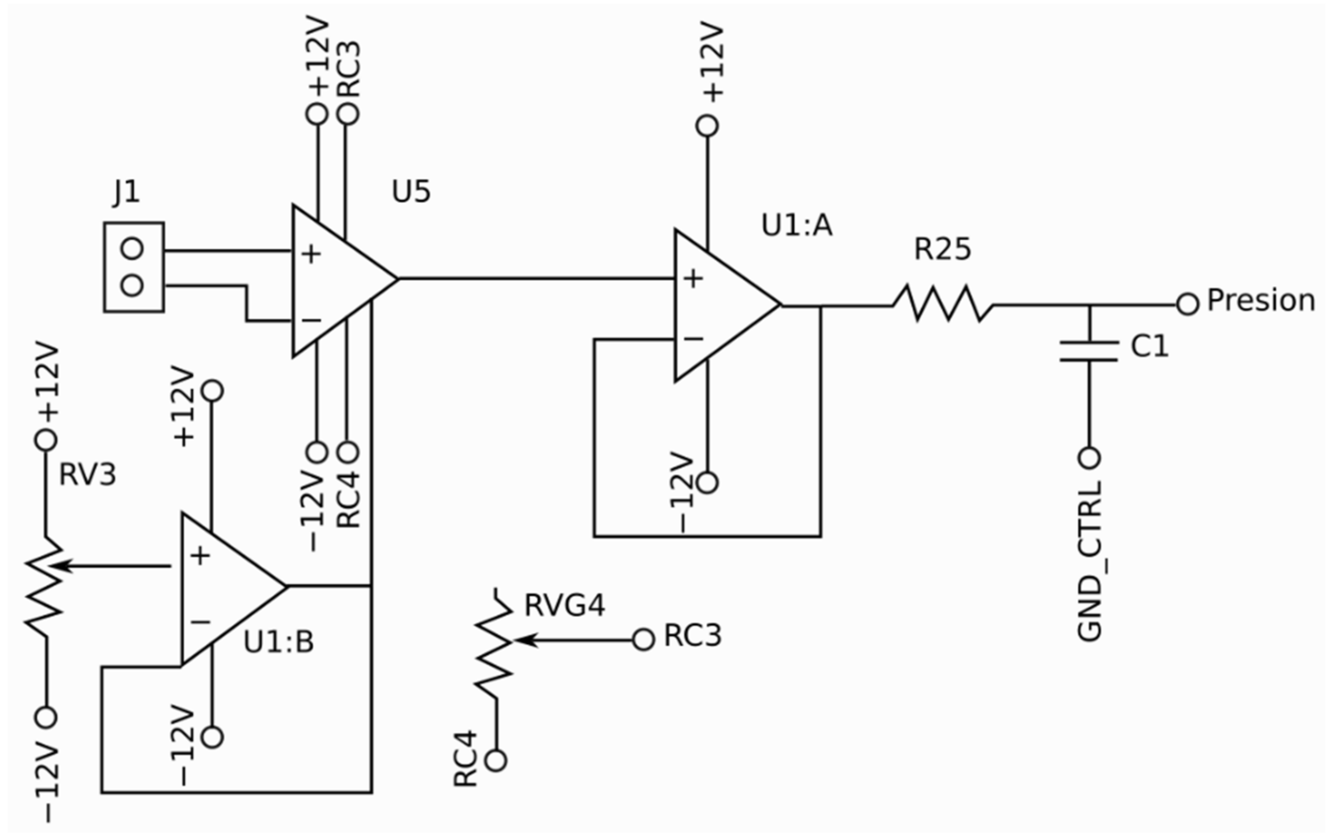
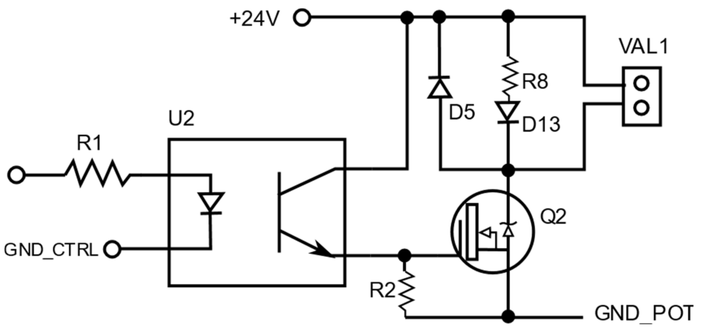
4.2.2. Electronic Design

The structure of the PCB must be designed for the modular use of electrical and electronic components, the latter being more sensitive to electromagnetic interference (EMI), instability, and a decrease in the lifetime of the circuit [48]. For this reason, and in order to not have two independent sources, it is recommended to have two different DC power branches (one for the electrical elements and one for the electronic elements). The reference voltage (0VDC) of both branches is only at one point at the beginning [23], taking into account that a DC/DC converter must separate the positive voltage of both branches because, generally, the electronic elements operate at 5 V while the electrical elements operate at 12 V.
To control the flow and pressure, signals are sent to the pneumatic final control elements (proportional valves and all/nothing valves). To calculate control actions, signals are processed by an embedded system [45].
According to the functional and reliable design of the mechanical ventilator presented in [23], an integrated system operating with an ATMEGA 328P microprocessor was determined to be reliable enough to control the functionality of mechanical ventilators where airway pressure, inhalation flow, expiratory flow, and oxygen level of the inlet gas are efficiently managed. The control of these variables is a slow process; therefore, the embedded system will not present considerable difficulties or delays in controlling the same. However, it is not enough to generate pressure or flow graphs [8,46]. For ventilators with a visual interface using a touch screen that gives the intensivist access to control and configuration parameters, embedded systems with higher performance and capacity should be used due to the increase in system graphics resources [7]. Therefore, for this type of equipment, the use of embedded systems based on a Broadcom BCM2837 SoC, 64-bit Cortex-A53 (ARMv8) at 1.4 GHz (1 GB LPDDR2 SDRAM) [20] is ideal for image handling, as well as allowing the use of open-source software. However, to the authors’ knowledge, image processing may take longer than expected in some cases, which may result in not always having a suitable control signal (non-fixed frequency PWM signal). It is recommended to replace this function with a low-cost embedded system that can be easily coupled to the master system, for which an additional system based on an ATMEGA328P microcontroller—or even an ATTINY85—can be used.
Sensors must measure pressure, oxygen concentration, and gas flow signals in inhalation and exhalation lines [18]. Once the embedded system has processed and calculated the control actions from the calls obtained from the sensors, the actions must be sent to the final control elements (proportional valves and ON/OFF valves) [45]. To measure the signals, it must be considered that there are ready-to-install sensors on the market that already have an adequate output to be coupled to the chosen recessed system. Hence, it is only a matter of choosing those with the minimum required characteristics, considering that they are used for medical scenarios and have temperature compensation to avoid measurement fluctuations.
Table 3 shows the components, applications, and characteristics that can be considered in mechanical ventilators. The selection of these components considers accessibility of elements in local areas.
The pressure sensor selection in the airway considers the alveolar pressure in the patient’s lungs at the mechanical ventilation time. This pressure varies between 0 cm H2O and 60 cm H2O [10], which is equivalent to 5.88 kPa, so a sensor with a measurement range between 0 kPa and 10 kPa must be used to detect overpressure while not losing the sensitivity of the sensors. Sensors of this type (specifically from the MXP5010DP series) were applied in the development of a mechanical ventilator in [48] due to their adequate measurement range, medical use, and sensitivity of 4.413 mV/cmH2O, which makes their measurements interpretable by any embedded system that has an analog input from 0 Vdc to 5 Vdc. A wiring diagram of this sensor is shown in Figure 4.
For the appropriate selection of flow sensors, the measurement of the oxygen-rich gas entering the patient (inhalation) and the saturated carbon dioxide gas leaving the patient (exhalation) should be measured considering flows ranging from 0 L/min to 90 L/min in both cases [46]. There are several ways to measure these flows; mechanical ventilator developers have tested some of these methods [14] and have demonstrated very complex but efficient coupling circuits. However, sensors capable of measuring these flows suitably, which are for medical use and have an easily coupled output, are also commercially available. Sensors from the PMF4101V series (See Figure 5) [12] can be used for measurements in the range of 0–100 l/min. In addition, they have temperature compensation, an output between 1 Vdc and 5 Vdc, and are characterized by their use in medical equipment. They are also inexpensive, suitable for mechanical ventilation, and can be easily coupled to any integrated system to calculate the air volume entering and leaving the patient.
The oxygen concentration in the fluid provided to the patient through the mechanical ventilator varies between 21 and 100% [10] and depends on the patient’s scenario and the recommendations of the intensive care specialists.
The sensors used in commercial mechanical ventilators [8,9,13] are a good alternative because they are spare components purchased in specialized centers. Several components are replaced once a year due to the internal chemical components reacting in the presence of oxygen.
For the embedded system to read the sensor signal, it is sufficient to perform conditioning, which consists of amplifying and calibrating the sensor output signal (8–40 mV) so that any embedded system can detect an output from 0 V DC to 5 V DC. For this, we can use the scheme in Figure 6, based on the design in [7].
Many medical-grade valves with proportional control and on/off actuation are available on the market. Integrated systems control these valves if the appropriate controller is available. In particular, some valves are only controlled by Boolean signals, i.e., logic controlled by ones and zeroes.
Finally, in Figure 7 shows a scheme for controlling proportional valves; to use it, the aperture must be controlled by varying the pulse width of the pulse-width-modulation (PWM) wave with a frequency of 1 kHz [8].

4.3. Interface and Control

Common and minimum parameters are used in multiple emerging devices such as Positive End Expiratory Pressure (PEEP), Peak Inspiratory Pressure (PIP), Respiratory Frequency (FR), Inspiratory Time (Ti), and Trigger and alarms [11,22,23], as well as others that provide features and advantages in the ventilation process such as patient data entry, identification, remote connectivity, temperature, etc.
The Python language is recommended to control and visualize common, minimum, and other functionalities. More specifically, this language allows the creation of a web server through the Flask library and the processing of independence with the Threading module, which allows the generation of simultaneous processes and mathematical calculations with the NumPy library.
An intuitive interface with low-delay information flows can be developed using a programming language such as JavaScript due to its dynamism, facilitating the updating of graphics without reloading the interface and incorporating external images. Both Python and JavaScript are open-access languages with sufficient reference documentation.

4.4. Recommended GUI Components

The functions and parameters indispensable for the complete configuration and monitoring of the mechanical ventilation process are presented in Table 4 [35], which shows the sets of functions, parameters, and graphs required by specialists to observe the evolution of the ventilation process. Section 1 is designed to provide information about identification, mode of operation, and the patient’s name. Pressure and gas flow graphs are presented in an evident and centralized display area. The alarms section is another aspect of important visibility, as well as the buttons that allow the configuration of the equipment.
A 15.6 inch screen facilitates the visualization of the different parts of the interface. This screen is positioned at 1.20 m above ground level so as not to force the user’s position when observing and manipulating the screen.
In Table 4, FiO2 is the percentage of oxygen in the air mixture delivered to the patient.

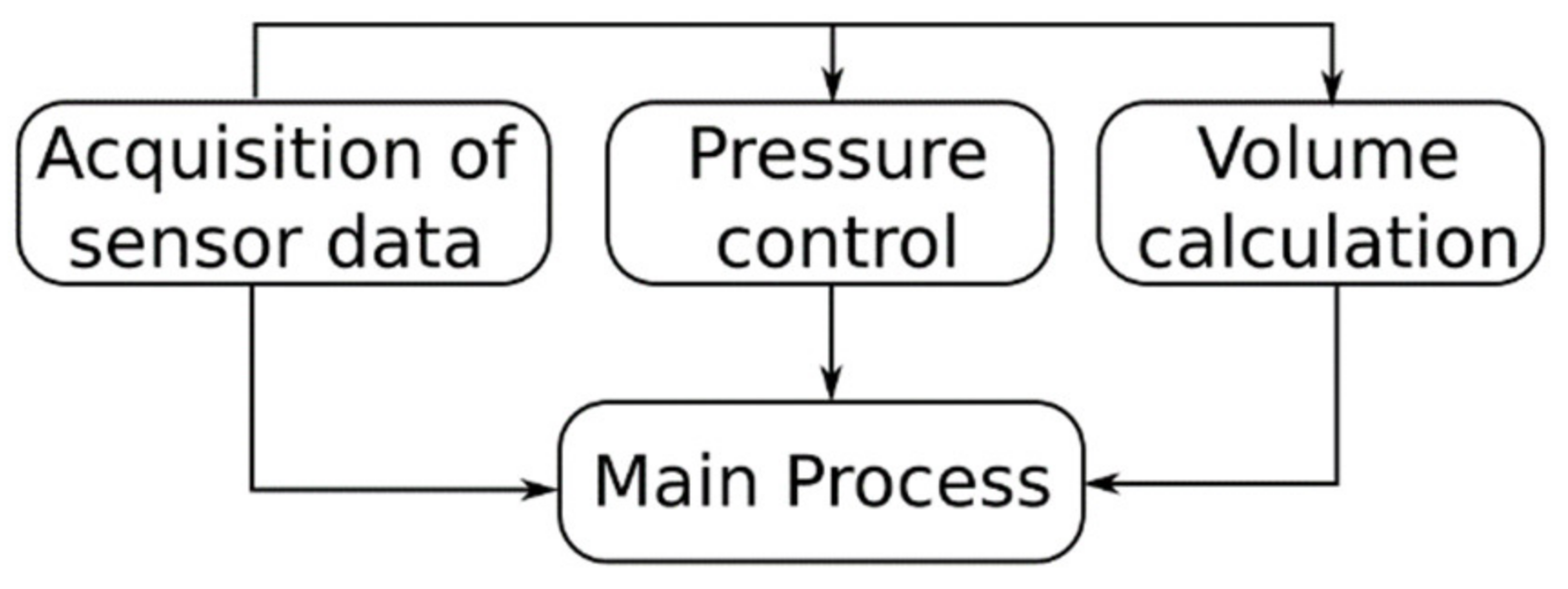
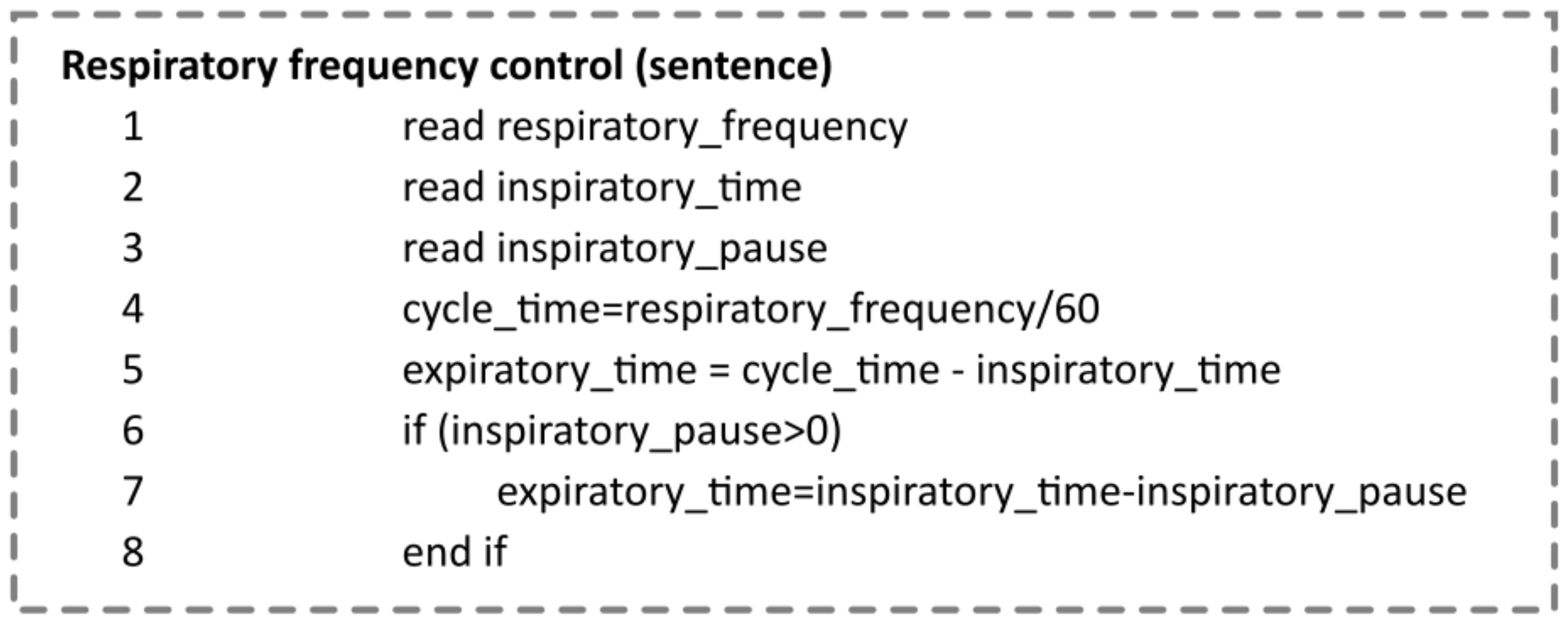
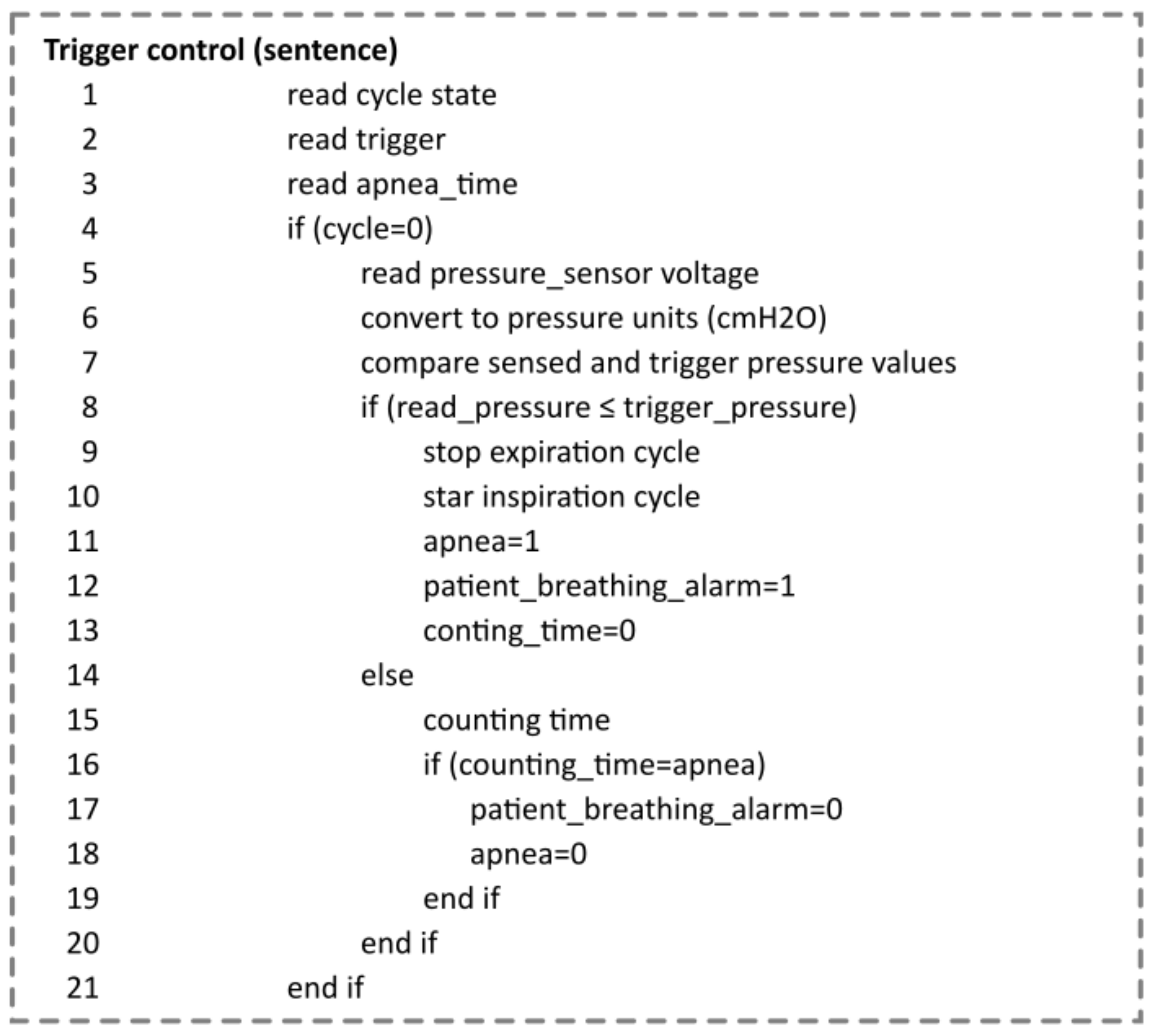
4.5. Ventilatory Variable Control Algorithms

Figure 8 [23] shows a block diagram showing the main mechanical emergent ventilator control processes. Pressure and volume control uses the information acquired from the pressure sensors to follow the desired and configured reference.
The primary process starts, executes, and controls all child processes. To visualize and monitor the variables, a web service is created that allows communication between the control algorithm and the interface, obtaining and sending the control, and reading values to the user.
A process is used for sensor values such as pressure and airflow in and out of the equipment to and from the patient. One process is responsible for PID control for the opening and closing of the inspiratory valve, and another for the calculations necessary to obtain the values to be displayed, such as volume, FiO2, pressures, and alarms to be displayed by the operator on the screen.
Due to the practically linear response of the pressure sensors mentioned above, the PIP value is obtained via
PIP = a × voltage b
where parameters a and b have been obtained by adjusting the sensor vs. voltage response curve and comparing it with the values obtained in a gas measurement pattern. For the cyclic control of the PIP value, the algorithm presented in Scheme 1 is used.
Scheme 2 presents the pseudocode for updating the PEEP value with this aim; the algorithm uses the reading of the pressure sensor value and closes the valve to maintain the set reference of this pressure.
Scheme 3 maintains the respiratory pressure within limits set by the user. To do this, it reads the value set in the configuration and obtains the inspiratory time and pause. It then determines the number of breaths per minute and the expiration time. From the value of the reading of the state of the cycle, and if the pressure does not register a normal behavior in operation, the system activates the respiratory cycle automatically, determining that the patient has apnea.
The system will alert the patient using an alarm while providing support and timely ventilator response to the patient. The algorithm presented in Scheme 4 is used for this process.

5. Results and Discussion

Applying the above criteria and fundamentals has served as the basis for developing the SURKAN mechanical ventilator, which offers adequate functionality and operability in pressure-controlled mode and continuous mandatory ventilation (PC-CMV).
Figure 9 shows the PIP pressure curve as a function of the time generated by the ventilator designed and the reference curve proposed in [49]. The red curve corresponds to the designed fan curve obtained from the graph data on the monitor for a PIP pressure of 30 cm H2O, while the black line curve is obtained from [49]; these two curves have been graphically adjusted to the same time interval to check the shapes. The fundamentals of the ventilator facilitated the implementation and reproduction of a device characterized by stable operation and complete and comprehensive graphical visualization of essential parameters for monitoring and configuration by the intensivist.
The equipment has been developed mainly with materials of Ecuadorian nationality that comply with the Ecuadorian standard NTE INEN-ISO 7153-1, except proportional valves and pressure sensors that have been imported from the United States and Europe, respectively.
In this development, modular systems have been considered, which considerably reduce the assembly time by allowing the pneumatic, electrical, electronic, and mechanical structure to be mounted simultaneously, thus facilitating the subsequent assembly of the equipment.
Figure 10 shows the equipment in operation and the representation of the PIP pressure behavior. The display is versatile and intuitive and can easily access tracking and control parameters. The mechanical ventilator weighs 21 kg, along with its components and accessories for implementation and assembly.
The margin of error is evaluated in the device against operation with variable parameters, obtaining values less than 5% in all controlled parameters.
While multiple electromechanical configurations exist to provide and ensure a proper ventilation process in intensive care units, all solutions commonly use components such as proportional control valves, pressure sensors, alarm systems, and user interfaces (the reference design presented in Figure 2 details a common scheme for many of the above developments).
Although companies engaged in high-level technological developments implement commercial equipment used in health centers, our work shows that it is feasible to design and implement competitive equipment with similar characteristics and functionalities that comply with international standards. The critical elements to achieve, especially in developing countries, are proportional valves and pressure or flow sensors. Companies in highly developed countries offer facilities for designing and manufacturing components such as valves with low response times. The featured design considers the use of Humphrey proportional balanced valves, imported from the U.S., which provide precise variable flow control of inert gases for critical applications and are readily available. In addition, an indispensable piece for implementing mechanical ventilators is Biomedical’s leading general-purpose gas flow analyzer, which, once certified and calibrated, provides reliability in developing the control of ventilation variables.
The electronic components required for the implementation of the mechanical ventilator are available in specialized stores at low cost with respect to the total cost of the equipment. The wide dissemination and commercialization of touch screens in sizes such as 15.6 inches provides the possibility of considering standard monitors to implement the graphical user interface.

6. Conclusions

The criteria presented in this document are useful and contribute to the design and implementation of mechanical ventilators which present acceptable behavior close to the operation of a pressure-controlled fan and allow continuous mandatory ventilation CMV. The ventilator generated represents a basis on which control strategies must be implemented that allow it to operate in new reference points and be used by a diverse range of patients. This mechanical ventilator and its design were developed to operate in intensive care units and connect to pressurized air and oxygen networks. The materials described for manufacturing the components include materials that are easy to obtain within the country. Some of them are industrial and allow transformation through simple technological processes. Regarding the reliability of electronic components, it is essential that their location in the equipment eliminates static loads and that noise suppressor filters improve their operability.
It has been proven that the technology that allows the operation of mechanical fans can be replicated using computer components, electronics, and industrial materials. The calibration tests have given satisfactory results and demonstrated the stability of the parameters.
From the use of the equipment by at least ten specialists, it was concluded that the designed ventilator meets the functional specifications required by the intensive care specialists. They have validated and corroborated the arrangement of the parameters in Figure 10 and commented that the equipment designed with the criteria described in this document is complete, intuitive, practical, and straightforward to use.

Author Contributions

Conceptualization, O.F., J.T. and J.Q.; methodology, P.A.-V. and H.C.; software, J.Q.; validation, H.C., M.F. and V.L.; investigation, J.T., J.Q. and V.L.; resources, O.F.; writing—original draft preparation, O.F., J.Q, M.F. and J.T; writing—review and editing, P.A.-V.; visualization, O.F.; supervision, P.A.-V., H.C. and M.F.; project administration, O.F.; funding acquisition, P.A.-V. All authors have read and agreed to the published version of the manuscript.

Funding

This research was funded by Universidad de Las Américas-Ecuador, as part of the internal research project INI.PAV.22.01 and project INI.PAV.22.02.

Institutional Review Board Statement

The mechanical ventilator design was not tested on humans or animals. An artificial lung was used.

Informed Consent Statement

Not applicable.

Data Availability Statement

The calibration sheets of the tests performed have not been provided as material for the development of this article.

Conflicts of Interest

The authors declare no conflict of interest.

References

  1. Universidad Salvadoreña Desarrolla Respirador Mecánico para Apoyar Hospitales. Diario La Tribuna, 26 March 2020. Available online: https://www.latribuna.hn/2020/03/26/universidad-salvadorena-desarrolla-respirador-mecanico-para-apoyar-hospitales/ (accessed on 22 October 2022).
  2. MPS Created an Open-Source Ventilator to Battle COVID-19. EEWeb, 14 April 2020. Available online: https://www.eeweb.com/mps-created-an-open-source-ventilator-to-battle-covid-19/ (accessed on 22 October 2022).
  3. Esta Iniciativa Española Diseñará Respiradores Artificiales Baratos Contra el Coronavirus. Available online: https://www.elespanol.com/omicrono/20200314/iniciativa-espanola-disenara-respiradores-artificiales-baratos-coronavirus/474454447_0.html (accessed on 22 October 2022).
  4. OEDK—Rice University—ApolloBVM. Available online: http://www.oedk.rice.edu/apollobvm (accessed on 22 October 2022).
  5. Coventor Emergency Ventilator—Adult Manual Resuscitator Compressor Available from Technology Commercialization. Available online: https://license.umn.edu/product/coventor-emergency-ventilator---adult-manual-resuscitator-compressor (accessed on 22 October 2022).
  6. VU Engineers and VUMC Doctors Team up for Open-Source Ventilator Design. Vanderbilt University, 27 March 2020. Available online: https://news.vanderbilt.edu/2020/03/27/vu-engineers-and-vumc-doctors-team-up-for-open-source-ventilator-design/ (accessed on 22 October 2022).
  7. Diseño de Placa para Respirador de Código Abierto. Revista Electrónica Convertronic—Noticias y Actualidad Electrónica. Available online: https://convertronic.net/semiconductores/diseno-2/8660-diseno-placaorespiradorocodigo-abierto.html (accessed on 22 October 2022).
  8. Pcb Prototype Manufacturing Factory Medical Ventilator. FASTPCBA, 11 April 2020. Available online: https://www.medicalpcba.com/product/pcb-prototype-manufacturing-factory/ (accessed on 22 October 2022).
  9. TheOpenVentilator. Available online: https://www.theopenventilator.com/ (accessed on 22 October 2022).
  10. Würth Elektronik Circuit Board Technology Produces PCBs for Ventilators | Würth Elektronik: Würth Elektronik Group > News. Available online: https://www.we-online.com/web/en/wuerth_elektronik/news_weg/News_Detail_WE_Gruppe_112665.php (accessed on 22 October 2022).
  11. Zhu, J.; Ren, Z.; Lee, C. Toward Healthcare Diagnoses by Machine-Learning-Enabled Volatile Organic Compound Identification. ACS Nano 2020, 15, 894–903. [Google Scholar] [CrossRef]
  12. Björklund, L.J.; Ingimarsson, J.; Curstedt, T.; John, J.; Robertson, B.; Werner, O.; Vilstrup, C.T.; Bj, L.J. Manual Ventilation with a Few Large Breaths at Birth Compromises the Therapeutic Effect of Subsequent Surfactant Replacement in Immature Lambs. Pediatr. Res. 1997, 42, 348–355. [Google Scholar] [CrossRef] [PubMed] [Green Version]
  13. Pasha, S.; Babar, E.T.R.; Schneider, J.; Heithaus, J.; Mujeeb-U-Rahman, M. A Low-cost, Automated, Portable Mechanical Ventilator for Developing World. In Proceedings of the 2021 IEEE Global Humanitarian Technology Conference (GHTC), Seattle, WA, USA, 19–23 October 2021; pp. 112–118. [Google Scholar] [CrossRef]
  14. Ochukpue, C.O.; Kingsley, T.U.; Ekwere, I. Abstract PR118: Mechanical Ventilation in the Intensive Care Unit in A Nigerian Hospital. Anesth. Analg. 2016, 123, 160. [Google Scholar] [CrossRef]
  15. Bayram, B.; Şancı, E. Invasive mechanical ventilation in the emergency department. Turk. J. Emerg. Med. 2019, 19, 43–52. [Google Scholar] [CrossRef] [PubMed]
  16. Vasan, A.; Weekes, R.; Connacher, W.; Sieker, J.; Stambaugh, M.; Suresh, P.; Lee, D.E.; Mazzei, W.; Schlaepfer, E.; Vallejos, T.; et al. MADVent: A low-cost ventilator for patients with COVID-19. Med. Devices Sens. 2020, 3, e10106. [Google Scholar] [CrossRef] [PubMed]
  17. Hess, D.R.; Kacmarek, R.M. Essentials of Mechanical Ventilation, 3rd ed.; McGraw Hill Education, Medical Publishing Division: New York, NY, USA, 2014. [Google Scholar]
  18. Flor, O.C.; Suarez, F.M.; Toapanta, C.F.; Rosales, L.D.; Alvarez, G.A. Alvarez, Evaluaciones matemáticas de los mecanismos para ventiladores artificiales emergentes. Rev. Espac. 2020, 41, 383–394. Available online: https://www.revistaespacios.com/a20v41n29/20412928.html (accessed on 22 October 2022).
  19. El Majid, B.; El Hammoumi, A.; Motahhir, S.; Lebbadi, A.; El Ghzizal, A. Preliminary design of an innovative, simple, and easy-to-build portable ventilator for COVID-19 patients. Euro-Mediterr. J. Environ. Integr. 2020, 5, 23. [Google Scholar] [CrossRef] [PubMed]
  20. Chatburn, R.L.; Mireles-Cabodevila, E.; Tobin, M.J. Chapter 3. Basic Principles of Ventilator Design. In Principles and Practice of Mechanical Ventilation, 3rd ed.; Tobin, M.J., Ed.; The McGraw-Hill Companies: New York, NY, USA, 2013; Available online: https://accessmedicine.mhmedical.com/content.aspx?bookid=520&sectionid=41692239 (accessed on 22 October 2022).
  21. Anda, G.F.V.-D.; Chávez, M.R.-D.; Pérez-Castañeda, A.I.; Vázquez-Moreno, P.; Dávila-Fernández, J.C.; Delaye-Aguilar, M.G. Mechanical ventilator as a shared resource for the COVID-19 pandemic. Gac. Médica México 2020, 156, 4892. [Google Scholar] [CrossRef]
  22. Garmendia, O.; Rodríguez-Lazaro, M.A.; Otero, J.; Phan, P.; Stoyanova, A.; Dinh-Xuan, A.T.; Gozal, D.; Navajas, D.; Montserrat, J.M.; Farré, R. Low-cost, easy-to-build noninvasive pressure support ventilator for under-resourced regions: Open source hardware description, performance and feasibility testing. Eur. Respir. J. 2020, 55, 2000846. [Google Scholar] [CrossRef] [PubMed] [Green Version]
  23. Flor, O.; Naranjo, C.; Tapia, J.; Flores, E.; Coba, A.; Chango, E. Diseño de ventilador mecánico emergente en modo asistido/controlado y espontáneo por presión. SciELO Prepr. 2020, 1, 130–137. [Google Scholar] [CrossRef]
  24. UNE EN ISO 10993-12:2022; Biological Evaluation of Medical devices—Part 12: Sample Preparation and Reference Materials. UNE: Madrid, Spain, 2022. Available online: https://www.en-standard.eu/une-en-iso-10993-12-2022-biological-evaluation-of-medical-devices-part-12-sample-preparation-and-reference-materials-iso-10993-12-2021/ (accessed on 22 October 2022).
  25. Council Directive 93/42/EEC of 14 June 1993 Concerning Medical Devices. Available online: https://www.legislation.gov.uk/eudr/1993/42/2007-10-11 (accessed on 22 October 2022).
  26. UNE-EN ISO 10993-15:2009; Evaluación Biológica de Productos Sanitarios. UNE: Madrid, Spain, 2009. Available online: https://www.une.org/encuentra-tu-norma/busca-tu-norma/norma?c=N0044133 (accessed on 22 October 2022).
  27. UNE-EN ISO 10993-13:2000; Evaluación Biológica de Productos San. UNE: Madrid, Spain, 2000. Available online: https://tienda.aenor.com/norma-une-en-iso-10993-13-2000-n0022378 (accessed on 22 October 2022).
  28. Rubio-Romero, J.C.; del Carmen Pardo-Ferreira, M.; Torrecilla-García, J.A.; Calero-Castro, S. Disposable masks: Disinfection and sterilization for reuse, and non-certified manufacturing, in the face of shortages during the COVID-19 pandemic. Saf. Sci. 2020, 129, 104830. [Google Scholar] [CrossRef] [PubMed]
  29. AAMI—Association for the Advancement of Medical Instrumentation. Dialysis Water Solutions, 2 June 2015. Available online: https://dialysiswatersolution.com/regulations-and-guidelines/ansiaami/ (accessed on 22 October 2022).
  30. Kalpakjian, S.; Schmid, S.R. Manufactura, Ingeniería y Tecnología. Pearson Educación: London, UK, 2002. [Google Scholar]
  31. Ashby, M.F.; Shercliff, H.; Cebon, D. Materials: Engineering, Science, Processing and Design, 1st ed.; Butterworth-Heinemann: Amsterdam, The Netherlands; Boston, MA, USA, 2007. [Google Scholar]
  32. Torres Velásquez, J.A.; Viáfara Avila, R.R.; Chacón Cardona, C.A. Study of Magnetic Shielding in Conductors Materials as a Function of the Frequency. Cienc. Desarro. 2016, 7, 55–61. [Google Scholar] [CrossRef] [Green Version]
  33. Williams, T. EMC for Product Designers, 5th ed.; Newnes: Oxford, UK, 2017. [Google Scholar]
  34. Posada, A.O.G.; Téllez, D.A.L.; Rojas, J.R.; Barrado, J.R. Ciencia e Ingeniería Neogranadina, Materiales Compuestos de Matriz Polimérica Usados para el Blindaje de Interferencia Electromagnética. Available online: https://scholar.google.com/citations?view_op=view_citation&hl=es&user=CdPkP1AAAAAJ&citation_for_view=CdPkP1AAAAAJ:9yKSN-GCB0IC (accessed on 23 October 2022).
  35. Miño, C.; Flor, O.; Quiroga, J.; Cuaycal, A. Remote Variable Monitoring App for Mechanical Ventilators Used in COVID-19. In Artificial Intelligence, Computer and Software Engineering Advances; Botto-Tobar, M., Cruz, H., Díaz Cadena, A., Eds.; Springer International Publishing: Cham, Switzerland, 2021; Volume 1326, pp. 303–315. [Google Scholar] [CrossRef]
  36. Wilson, R.; Kuruvilla, J.; George, G. Materials for Potential Emi Shielding Applications: Processing, Properties and Current Trends; Elsevier: Waltham, MA, USA, 2019. [Google Scholar]
  37. ISO—ISO/CD 11137-1; Sterilization of Health Care Products—Radiation—Part 1: Requirements for Development, Validation and Routine Control of a Sterilization Process for Medical Devices. ISO: Geneva, Switzerland, 2006. Available online: https://www.iso.org/standard/81721.html (accessed on 23 October 2022).
  38. UNE-EN ISO 11135-1:2007; Esterilización de Productos Sanitarios. UNE: Madrid, Spain, 2007. Available online: https://www.une.org/encuentra-tu-norma/busca-tu-norma/norma/?c=norma-une-en-iso-11135-1-2007-n0039866 (accessed on 23 October 2022).
  39. UNE-EN ISO 17665-1:2007; Esterilización de Productos Sanitarios. UNE: Madrid, Spain, 2007. Available online: https://www.une.org/encuentra-tu-norma/busca-tu-norma/norma/?Tipo=N&c=N0039217 (accessed on 23 October 2022).
  40. Dempsey, D.J.; Thirucote, R.R. Sterilization of Medical Devices: A Review. J. Biomater. Appl. 1988, 3, 454–523. [Google Scholar] [CrossRef] [PubMed]
  41. Mitchell, M.R.; Jerina, K.L. (Eds.) Fatigue and Fracture of Medical Metallic Materials and Devices; ASTM International: West Conshohocken, PA, USA, 2007. [Google Scholar] [CrossRef]
  42. Jain, A.; Ganesh, N.; Venkatesh, M.P. Quality Standards for Medical Devices. Int. J. Drug Regul. Aff. 2018, 2, 19–24. [Google Scholar] [CrossRef] [Green Version]
  43. John, K.R.S.; Narayan, R.J.; Gibbons, D.; Drummond, C.K.; Hdeib, A.; Khan, F.R.; Khan, M.; Zhou, Y.; Nag, S.; Banerjee, R.; et al. Biocompatibility of Metallic Materials for Medical Devices—The Effects of Corrosion and Corrosion Products. In Materials for Medical Devices; Narayan, R.J., Ed.; ASM International: Almere, The Netherlands, 2012; pp. 73–78. [Google Scholar] [CrossRef]
  44. Williams, D.; Flory, S.; King, R.; Thornton, M.; Dingley, J. A low oxygen consumption pneumatic ventilator for emergency construction during a respiratory failure pandemic. Anaesthesia 2010, 65, 235–242. [Google Scholar] [CrossRef] [PubMed]
  45. Gutiérrez Muñoz, F. Ventilación mecánica. Acta Médica Peru. 2011, 28, 87–104. [Google Scholar]
  46. Hemmati, R.; Wu, F.; El-Refaie, A. Survey of Insulation Systems in Electrical Machines. In Proceedings of the 2019 IEEE International Electric Machines & Drives Conference (IEMDC), San Diego, CA, USA, 12–15 May 2019; pp. 2069–2076. [Google Scholar] [CrossRef] [Green Version]
  47. Malik, N.H.; Al-Arainy, A.A.; Qureshi, M.I. Electrical Insulation in Power Systems, 1st ed.; CRC Press: Boca Raton, FL, USA, 2018. [Google Scholar] [CrossRef]
  48. Manosalva, O.A.N.; Traslaviña, N.M.P. Reporte de la experiencia en la realización de ensayos de compatibilidad electromagnética sobre ventiladores mecánicos en Colombia. Rev. Ing. 2020, 50, 54–71. [Google Scholar] [CrossRef]
  49. Restrepo, R.D.; Serrato, D.M.; Adasme, R. Assessing Respiratory System Mechanical Function. Clin. Chest Med. 2016, 37, 615–632. [Google Scholar] [CrossRef] [PubMed]
Figure 1. Components of a mechanical ventilator for use with a network of oxygen and medical air in an ICU. The components are detailed in [20].
Electronics 11 03910 g001
Figure 2. Block diagram with the fundamental components for the design of mechanical ventilators.
Electronics 11 03910 g002
Figure 3. Filter electrical schematic for IEC PS00XDH3A [19].
Electronics 11 03910 g003
Figure 4. Pressure sensor schematic.
Electronics 11 03910 g004
Figure 5. Flow sensor from PMF4101V series.
Electronics 11 03910 g005
Figure 6. Oxygen sensor wiring diagram.
Electronics 11 03910 g006
Figure 7. Simple control scheme of a proportional valve [7].
Electronics 11 03910 g007
Figure 8. Block diagram of principal processes.
Electronics 11 03910 g008
Scheme 1. Pseudocode for PIP pressure control.
Electronics 11 03910 sch001
Scheme 2. Pseudocode for PEEP pressure control algorithm.
Electronics 11 03910 sch002
Scheme 3. Pseudocode for frequency control.
Electronics 11 03910 sch003
Scheme 4. Pseudocode for trigger control.
Electronics 11 03910 sch004
Figure 9. Designed ventilator pressure curve vs. reference curve.
Electronics 11 03910 g009
Figure 10. Mechanical ventilator SERKAN.
Electronics 11 03910 g010
Table 1. Characteristics of materials that can be used in EMI shields.
MaterialElectrical Resistivity (Ohm-cm)Relative PermeabilityModulus of
Elasticity (GPA)
Tensile Strength (MPa)Specific Weight (kN/m3)The Frequency Range of Attenuation (Hz) [7]
Copper0.000001700.9999911021076,16532,000 a 100,000
Low-carbon steel0.00001431.07520536576,52060–12,000
Aluminum0.000002701.0000236812526,47760–32,000
Mu metal0.0000850800020671586,3281000–10,000
Permalloy0.000085020,0002067156821000–10,000
Table 2. Electrical elements’ power consumption.
ElementQuantityUnit Power Consumption
(W)
Total Power Consumption
(W)
Embedded system (with graphics generation capability)112.512.5
Proportional valve (inhalation and exhalation)2816
Relief valve122
Cooling Fan11010
Electronic board with sensors11010
Total Power Consumed 45.5
Table 3. Features of some components commonly used for mechanical ventilator implementation.
ComponentApplicationCharacteristics
Embedded system
Raspberry P13 B
Embedded system
Arduino Nano
Master controller and graphics emitter
Proportional valve controller
Broadcom BCNQ 83 7B Corter-A53 64 bit SoC at 1.4 GHz 1 GB LPDDR2 SDRAM
5 V/2.5ADC via micro USB connector
1 × full-size HDMI, Amel AT mega 328
5 V DC via micro USB connector
Proportional valve
Humphrey 10032300
Relief valve ASCO
411L3112FVO
Inhalation Line Control Valve
Valve for rapid pressure relief
Ideal design for precision air or inert gas delivery control (0–100% proportional opening)
Operator voltage: 12 V DC, 2.0 W
Convertor DC/DC
MDS20A-06
Allows converting the supply voltage (12 V) to the power supply voltage of the embedded systemIdeal input voltage: 12 V (9–18 V)
Output: 5 V, 400 W Max, Efficiency: 86%
Pressure sensor
MXP5010DP
Allows measurement of airway pressureMeasuring range: 0 to 10 kPa, Supply voltage: 5VDC, Sensitivity:4 413 mV/cmH2O
POSIFA Flow Sensor
PMF4101 V
Allows measurement of airway pressureMeasuring range: 0–10 kPa
Supply voltage: 5 V DC
Sensitivity: 4,413 mV/cmH2O
Measuring range: 0–1001 min
Supply voltage: 6–10 V DC
Analog output: 1–5 V DC
Allows the oxygen level of the gas entering the patient to be measured with a small amount of conditioningMeasuring range: 21–100%.
Analog output: 8–40 mV
Table 4. Useful components for user interface design used in the emerging mechanical ventilator [23].
Parameter ControlGraphicsSensed Parameter ViewerOther Relevant Functions
PIP
PEEP
FR
Ti
Inspiration pause
Trigger
Pressure vs. time
Flow vs. time
PIP
Tidal Volume
Minute Volume
FR
FiO2
Trigger
Patient identification
Alarms
Configuration of equipment buttons
Ventilation mode identification
Publisher’s Note: MDPI stays neutral with regard to jurisdictional claims in published maps and institutional affiliations.

