Recent Progress in Precision Machining and Surface Finishing of Tungsten Carbide Hard Composite Coatings


1
Surface Engineering and Precision Institute, School of Aerospace, Transport and Manufacturing, Cranfield University, Cranfield MK43 0AL, UK
2
Hardide Coatings Plc, Bicester OX26 5AH, UK
*
Author to whom correspondence should be addressed.
Coatings 2020, 10(8), 731; https://doi.org/10.3390/coatings10080731
Submission received: 29 June 2020
/
Revised: 20 July 2020
/
Accepted: 23 July 2020
/
Published: 25 July 2020
(This article belongs to the Special Issue Hard Coatings in Research and Industry)
Abstract
:Owing to their high hardness, fracture toughness and oxidation resistance, tungsten carbide (WC) coatings are extensively deposited on parts that operate in demanding applications, necessitating wear, erosion, and corrosion resistance. The application of thick and hard WC coatings has an inevitable effect on the original dimensions of the parts, affecting the geometrical tolerances and surface roughness. The capability of achieving a sub-micron surface finish and adhere to tight geometrical tolerances accurately and repeatably is an important requirement, particularly with components that operate in high-precision sliding motion. Meeting such requirements through conventional surface finishing methods, however, can be challenging due to the superior mechanical and tribological properties of WC coatings. A brief review into the synthesis techniques of cemented and binderless WC coatings is presented together with a comprehensive review into the available techniques which are used to surface finish WC-based coatings with reference to their fundamental mechanisms and capabilities to process parts with intricate and internal features. The binderless WC/W coating considered in this work is deposited through chemical vapour deposition (CVD) and unlike traditional cemented carbide coatings, it has a homogenous coating structure. This distinctive characteristic has the potential of eliminating key issues commonly encountered with machining and finishing of WC-based coatings. Here, six contact and non-contact surface finishing techniques, include diamond turning, precision grinding, superfinishing, vibratory polishing, electrical discharge machining, and electropolishing are discussed along with their current use in industry and limitations. Key challenges in the field are highlighted and potential directions for future investigation, particularly on binderless WC coatings, are proposed herein.
1. Introduction
Hard coatings are synthetic tribological layers which provide protection against wear, abrasion and corrosion, in extreme mechanical loading and elevated thermophysical conditions. They are commonly deposited on cutting, forming, machining and moulding tools to improve their functional performance and extend their service life – permitting cost reductions [1]. Materials with excellent hot hardness and fracture toughness, along with superior chemical stability and oxidation resistance at high temperature, are the best candidates for hard coatings. They are typically made of ceramics in the form of transition metal oxides, carbides, nitrides and borides, along with carbon-based compositions. Some of the most commonly used hard coatings in industry include aluminium oxide (Al2O3), titanium nitride (TiN), cubic boron nitride (cBN), chrome carbide (CrC), silicon carbide (SiC), vanadium carbide (VC) and diamond-like carbon (DLC) coatings [2].
Amongst a wide range of existing hard coatings, tungsten carbide (WC) has shown a promising potential owing to its high hardness and superior mechanical properties [3]. WC was discovered in 1893 and since the beginning of the 20th century it has been predominantly used as a base material for cutting tools [4]. Towards the 1940s and 1950s, industrial demands have led to scientific developments into the use of WC as a surface coating to improve the functional performance and service life of components. Since then, different coating deposition techniques have been developed which have been employed in several engineering applications to modify and reinforce the surfaces of bulk materials, primarily to improve the corrosion and wear resistance. WC is the pinnacle of hard, stiff, and wear-resistant technical ceramics. Its hardness level can be in excess of 3000 Hv, a compressive strength of 3360 MPa, an elastic modulus greater than 600 GPa and a wear rate below 7 × 10⁻⁷ mm3/Nm [5,6,7]. A comparison of the Hardness and Young’s modulus of WC against other technical ceramics is shown in the Ashby diagram (Figure 1).
In many cases, apart from providing high wear and corrosion resistance, the applications of WC coatings also demand sub-micron surface finish and require tight dimensional tolerances. However due to the coatings’ superior mechanical properties, particularly high hardness, meeting such specifications through conventional surface finishing methods can be challenging. This problem is exacerbated when the coated parts have complex geometries with intricate, defined features, which require dedicated finishing techniques. This review delves into the available and most suitable precision machining techniques capable of achieving high surface finish and meet tight geometrical tolerances on hard coatings, with specific reference to WC-based coatings. It is by and large the case that precision surface finishing techniques have been primarily developed to process uncoated materials with relatively low hardness, when compared to hard coatings. However, with application requirements becoming more stringent, the need to adapt these techniques to process hard coatings continues to grow. This requirement in itself, brings with it a number of considerations which have to be made, including the effect on surface and sub-surface integrity of the coating, coating’s electrical conductivity, coating/substrate bonding strength and ductile machining properties [9].
WC is a well-established hard coating material used in a wide range of industries as a replacement to other protective coatings, such as the widely used hard chromium coating. The key driver can be attributed to the tight restriction on the use of hexavalent chromium, which is the main component in plating of hard and decorative chromium coatings, under environmental and health and safety regulations due to its severe adverse health effects [10,11]. Whilst significant developments have been made within the last decades on understanding of machining and finishing techniques and mechanisms of WC coatings [12,13,14,15], these studies focus on cemented carbide coatings. Note that cemented carbide coatings comprise of hard WC grains embedded within soft metal binder matrices, such as cobalt, iron or nickel, and are commonly deposited through a line-of-sight vapor or liquid electrochemical process [16,17]. The presence of hard and soft phases in the coatings leads to spatial phase heterogeneity that often results in selective material removal, grain fracture, and formation of microcracks when these coatings undergo machining and finishing processes [18,19]. This soft metal binder also leads to an additional challenge associated with graphitisation of diamond-containing machining and finishing tools [20]. The emergence of a new WC-coating variant e.g., tungsten-matrix WC coating (WC/W) deposited by a non-line-of-sight process, offers new opportunities and challenges related to deposition characteristics and phase homogeneity. It is therefore imperative and timely to critically review the available techniques that may allow precision machining and finishing of WC-coated parts with internal features and intricate geometries.
Here, a number of precision machining and surface finishing techniques, including electrical discharge machining (EDM), electropolishing, diamond turning, precision grinding, superfinishing, and vibratory polishing are reviewed, in the context of their capability of being used to process WC-coated parts with complex geometries, tight dimensional tolerances, and precise surface finish requirements. Conventional machining and finishing techniques typically revolve around rough grinding or turning operations using abrasive techniques. The aim of this work is to review these techniques from a perspective of their suitability for use on WC coatings. More advanced techniques are considered which are more innovative and have the potential of addressing stringent geometrical and finishing requirements. The main considerations when assessing the suitability of a machining or finishing process include the modification effects of processes on the surface of the coating manifested in the form of coating-deposition defects, induced residual stresses, formation of micro-cracks, plastic deformation, and the fragmentation of WC grains; these defects and failures are discussed [21,22,23]. Common root causes to such failures commonly involve the presence of high frictional forces and in the case of cemented carbide coatings, their inhomogeneous structure resulting in selective material removal. This review also outlines technical and economic considerations which should be carried out prior to selecting a surface finishing technique for a specific application including machining rates and flexibility of the process. It provides a comprehensive portfolio and systematic understanding of different surface finishing techniques to serve as a knowledge base for adding value to hard coated parts and for future development of machining and finishing techniques. It is, however, evident that in some cases it is difficult to have all the relevant information available due to the fact that in some cases no scientific studies have been conducted and the available information is solely based on experience.
2. Materials Synthesis
WC coatings are typically deposited as single-phase ceramic films or as mix composites, where WC crystalline nanoparticles or different-sized powders in the micron range, are dispersed within metal matrices. Similar to other hard coatings in a form of transition metal oxides, nitrides, borides and carbides, WC composites are typically deposited by means of electrodeposition, thermal spray techniques, and vacuum deposition techniques, such as chemical vapour deposition (CVD) or physical vapor deposition (PVD) [24]. Variations to the latter two processes, which are also widely used, include plasma assisted CVD (PACVD) and high-power impulse magnetron sputtering (HiPIMS). The deposition technique used is often based on the functional requirements which are expected from the coating and the associated costs. Other considerations include the microstructure of the coating, which has a direct bearing on the mechanical properties of the coating, and the geometry of the part, which dictates the feasibility of the technique being employed.
2.1. Electrodeposition
Electrodeposition (Figure 2) is the oldest and one of the most economical techniques of depositing metal matrix composite coatings onto a conductive surface. Electrodeposition of WC has been widely explored whereby WC nanoparticles are mixed in an electrolyte solution and transported towards a cathode along with metal ions which are then incorporated together to form a metal film [25]. Different variants of WC-based coating deposited through this technique have been developed and include mix composites of tungsten carbide particles in a nickel matrix (Ni/WC), a cobalt matrix (Co-WC), a nickel-cobalt matrix (Ni-Co/WC), and tungsten and silicon carbide particles in chromium matrix (Cr-SiC-WC) [16,26,27,28,29]. The combined, co-deposited particles serve distinctive functional properties predominantly zthose of improved wear and corrosion resistance due to increased hardness and formation of porous-free films.
2.2. High-Power Impulse Magnetron Sputtering (HiPIMS)
Over the last ten years, high-power impulse magnetron sputtering (HiPIMS) (Figure 3) has gained interest as a coating deposition technique due to its improvements over conventional PVD techniques producing better-quality films. The main benefits of the process are the formation of highly dense single-phase films with good substrate adhesion and low surface roughness [31]. HiPIMS is a line-of-sight deposition process whereby sputtering of a source occurs in a magnetic field with a high degree of ionization, allowing more collisions to take place near the substrate, forming high purity films. Despite improvements, the deposition rate in HiPIMS is relatively low when compared to conventional magnetron sputtering, affecting its economic efficiency. This is mainly attributed to the fact that some of the new sputtered ions are retuned back to the target [32].
The use of HiPIMS for the deposition of single-phase WC coatings has been explored by some researchers using different parameters and producing different coating variants, due to the use of different source materials and reactive hydrocarbon gases such as acetylene (C2H2) and methane (CH4) [33]. Coating thickness of WC coatings are reported to range from sub-micrometer up to 8 µm with a hardness range of 11–40 GPa. The mechanical properties of the coatings can be largely variable due to the variation of several operational parameters including the bias voltage, vacuum pressure, power density, pulse time durations and temperature.
2.3. Thermal Spraying
Thermal spraying is a versatile coating deposition process which has been widely used by several industries for many decades. The deposition technique involves the heating of materials in the form of powder, wire or rod, to the molten or semi-molten state, using thermal energy, either through combustion or electrical methods. The heated material is then projected onto the surface to form “splats”. Upon deposition, the splats are rapidly cooled and as they contract, a mechanical bond is formed with the substrate and adjacent splats. The coating is built-up in this manner, layer-by-layer (Figure 4a) [34]. Prior to coating deposition, the substrate is grit blasted to provide the roughness required to achieve the necessary strong bond between the coating and the substrate. Different thermal spray technologies have been developed which differ from each other depending on the heating methods and media which are used, and the way they are projected and propelled onto a surface. The most commonly used techniques include detonation gun deposition (D-gun), high velocity oxy-fuel (HVOF), air plasma spray (APS) and cold spray [35]. HVOF is usually the preferred technique as it typically leads to WC coatings with a higher hardness and a lower porosity [36].
Thermal spraying is commonly used for deposition of single-phase materials, layered or graded materials, and composite materials such as cemented carbide coatings. Cemented carbide coatings are composed of hard WC grains and a soft metal binder, such as cobalt, iron or nickel, used to improve the ductility of the coating whilst increasing the fracture toughness. The WC and soft binder particles are mechanically bonded together. Cemented carbide coatings such as WC-Co however, are susceptible to deteriorations in hardness at elevated temperatures, due to their inferior chemical characteristics and thermal expansion coefficient misfit of cobalt [38]. The relatively low melting point of cobalt may also lead to excessive adhesive wear, particularly when in contact with high plasticity metals such as iron [38]. Nonetheless cemented carbide coatings are still the most widely used type of WC-based coatings, having a total market share of 61% (as of 2018) of the whole WC market [39].
The main benefits of thermal spraying include the possibility of depositing materials with a higher melting temperature than that of the substrate, and the ability to coat large parts, as this is an atmospheric process. However, since the process is a line-of-sight process, it is limited when it comes to coating internal features with deep cavities and small parts with intricate features. Porosity is another inherent problem of thermally sprayed coatings resulting from un-melted particles and unfilled gaps between the deposited splats [40].
2.4. Chemical Vapour Deposition (CVD)
Chemical vapour deposition (CVD) is a process involving the deposition of a solid film onto a heated surface as a result of a chemical reaction in the vapour phase [41]. The process involves the diffusion of gases towards a heated surface and adsorption of reactants, followed by a chemical reaction forming a solid film (Figure 5) By-products from the chemical reaction are desorbed and diffused away from the surface. The key variables in the CVD process include the pressure, flow rates, temperatures and deposition time.
CVD is a non-line-of-sight process and thus capable of coating complex parts with internal features. The main limitation of CVD is the thermal effects which the process has on the substrate. Materials that are unstable at high temperatures cannot be processed using CVD as their mechanical properties are degraded. Another limitation is the potential formation of toxic and hazardous by-products which require a neutralisation process. Also, parts being coated must be completely enclosed inside the CVD reactor chamber, which has a size limit.
Over the last 20 years, CVD has been used for the development of a new tungsten-matrix WC coating (WC/W) [43]. CVD WC/W coating consists of WC nanoparticles dispersed within a tungsten metal matrix and is pore-free, as it is crystallised atom-by-atom from gas media. The coating provides an enhanced hardness of 800–1600 HV and a thickness range of 5–100 µm. As opposed to cemented carbide coatings, WC/W coatings are binderless, i.e., cobalt, iron, or nickel free, and pore-free, and as they are deposited through a gas-phase process, it is possible to coat complex geometries with intricate features and internal surfaces (Figure 6). WC/W coatings have been proven to provide enhanced wear and corrosion resistance and are able to operate in extreme conditions, consequently being employed in various industries for aerospace applications, power generation, metal forming, and extrusion die-casting applications [43].
2.5. Selection of WC Deposition Techniques
The choice of selecting a coating deposition technique is based on a number of criteria. These include the properties of the substrate material, particularly its conduciveness and its tolerance to high temperatures, the level of complexness and the operating environment of the component in question. Table 1 summarises the strengths and limitations of different coating deposition techniques commonly used to deposit WC-based coatings. In general, vaporised-based techniques, e.g., PVD sputtering and CVD, produce films with low levels of porosity and good substrate/coating adhesions. However, some of these techniques, e.g., HVOF and CVD, involve the use of thermal processes at a very high process temperatures and activation energies to achieve a high deposition rates [44]. A high coating thickness is often beneficial in many cases due to increased substrate protection providing a longer lifetime of the functional part. Table 2 provides a comparison of the characteristics of WC-based coatings and other hard coatings commonly used in industry. The table outlines the range of possible coating hardness and thickness which can be achieved through different techniques. Where available a reference to the coating’s level of porosity is given.
Complex parts with internal features and shadowed areas can only be conformally coated through non-line-of-sight processes namely CVD and electrodeposition techniques. However, despite electrodeposition being a far cheaper process than CVD, it provides an inferior coating in terms of hardness, substrate adhesion and coating deposition rate capabilities, which ultimately affect the level of protection offered to the coated component. In addition, the electrodeposition setup to achieve conformal coating on complex geometries is often non-trivial due to the high dependency on the distribution of electric field across the entire parts. Nonetheless, CVD requires high vacuum and involves the use and generation of toxic precursor and exhaust gases which require a neutralization process, significantly adding up to the operational costs of the process. As outlined in Table 2, WC/W deposited through CVD can provide a wide range of hardness and thickness combinations, making them suitable in a wide range of applications, when compared to other hard coatings.
Magnetron sputtering and thermal spray both offer good coating-substrate adhesion. However, both techniques are line-of-sight processes and not suitable for parts with complex geometries. Very hard but thin coatings deposited through magnetron sputtering may suffer from the so-called “eggshell effect” when used in high load bearing applications. On the other hand, thermal spray techniques can provide high coating thickness due to their high coating deposition rate.
3. Precision Machining Requirements
The demand for machining highly precise components originates from the need to provide high performance and reliability. In manufacturing terms, this is achieved through stable parts with low surface roughness, accurate sizing and surface integrity where the wear and fatigue life would be maintained and improved. The focus of precision machining has evolved throughout the years and is still an evolving concept. Initially, the main focus was for development of precision optical lenses for the aerospace industry. In the beginning of the 1990s, precision machining started to be employed in the manufacturing of other high-tech applications including in automotive, medical instruments, power generation and machining of precise moulds [53]. New challenges were introduced when difficult-to-machine materials started to be used including titanium and composite parts in aerospace and ceramic materials. Whilst the use of surface engineering in providing hard, protective layers continues to be widely employed in manufacturing, of equal importance is the development of suitable machining and finishing techniques capable of processing difficult-to-machine materials and hard coatings. Common machining and finishing requirements entail adherence to tight geometrical tolerances, sub-micron surface finishes and precise sizing which when combined with hard-coated parts pose new challenges, requiring the re-invention of existent techniques and development of new methods.
3.1. Surface Finish
In engineering, the term surface finish is commonly used interchangeably with surface roughness. However, surface finish refers to the overall texture and topography of a surface. It is an essential manufacturing measure which controls the quality of a part and is best described using three main factors which are the surface roughness, waviness, and lay (Figure 7). The surface roughness refers to the surface irregularities which are generated on the surface as a result of the machining process. Common parameters which are used to describe the surface roughness include the Ra and Rms. The Ra is the arithmetic mean of peak height (Rp) and valley depth (Rv), whilst the Rms refers to the root mean square of the microscopic Rp and Rv values. Other surface parameters include measurements of the width, skewness, and kurtosis of the profile. The waviness of a surface refers to geometrical imperfections and is also termed as the macro-roughness of the surface. Waviness is usually the result of vibrations between the workpiece and the cutting tool, causing differences in the depth of cut. Whilst advanced techniques have been developed to characterise the surface roughness, detection of surface waviness relies predominantly on visual observations. Surface profilometers developed to measure waviness are usually expensive and time consuming to operate in high volume production environments. The surface lay refers to the direction of the dominant surface pattern and is the result of the impact which the cutting tool has on the surface. It can usually be visually observed and can have straight, circular or radial forms. In some cases, surfaces may have no lay direction due to very fine or random surface treatments such as electropolishing and wet blasting [54].
As innovation continues to push the boundaries of manufacturing capabilities, the requirement to achieve high surface finished components continues to increase. Surface finish is a critical requirement in many engineering applications, where it is crucial in the assembly process of different parts making up a complete system. In advanced technological industries such as in aerospace, high specification standards have to be met therefore requiring the execution of the best finishing techniques. The selection of a finishing technique is based on a number of factors including the effect it has on the integrity of the surface, its flexibility to be used on parts with complex geometries, the economics of the process and its capability of achieving the required specifications. The surface finish of a part becomes increasingly important when its function is dependent on its relative motion against another part, particularly under high load and high velocity conditions. A high surface roughness will result in increased friction ultimately causing wear, which could have detrimental effects on the functionality of the parts. Tool breakages and high maintenance costs are other important considerations. Other material properties which are affected include the fatigue life of the parts, corrosion and wear resistance. Whilst several surface finishing techniques have been developed throughout the years, most of these techniques were designed to work on relatively soft substrates such as steels and stainless steels. As hard coatings and other difficult-to-grind materials started to be used more commonly, the use of conventional finishing techniques started to become unsuitable and more advanced methods started to be employed. For this reason, the use of conventional surface finishing techniques are not suitable. The situation becomes even more challenging in the case of complex geometries with intricate features.
3.2. Geometrical Tolerance
Geometrical tolerance is defined as the maximum error of a component’s geometrical characteristic over its whole dimensional length or surface [56]. It is an important feature in manufacturing which ensures the functionality of the parts is not compromised, particularly when the parts operate in contact with other surfaces. Traditionally, tolerances were set by designers with a less scientific approach, whereby the tolerance would be decided after bargaining with the manufacturers rather than conducting a scientific analysis of what is technically and economically feasible to achieve. The level of required tolerancing has a direct impact on the manufacturing costs due to the required use of higher-end manufacturing techniques. As hard coatings have poor machinability, the level of tolerancing which can be achieved is commonly based on experience and individual skill, and is often limited to the capabilities of the available techniques [57]. Setting realistic geometrical tolerances depends on the knowledge of the finishing process and the associated costs. Statistical principles are widely used as a method of setting tolerances [58]. These approaches take into consideration two tolerance levels, including the “worst case scenario”, which is the one referring to the tighter, most ambitious tolerance levels and the statistical tolerance which refers to the most permitting tolerance, economically, and scientifically.
4. Contact Surface Finishing Techniques
Surface finishing techniques are commonly classified based on the type of energy sources used, including mechanical, chemical, electrical and electrochemical sources [59]. Here, surface finishing techniques are classified into contact and non-contact type techniques. Contact-type techniques refer to processes such as diamond turning, precision grinding, superfinishing and vibratory polishing, whereby a mechanical action is exerted on the workpiece’s surface through cutting tools and abrasive media. Due to the relative motion which is involved between rotating bodies, frictional forces are involved, causing heat generation and formation of residual stress. Such effects would have detrimental effects on substrates but would also have an impact on hard coatings which are typically not as tough. Large mechanical forces may also cause coating delamination if they exceed the substrate-coating bonding strength.
4.1. Diamond Turning
Diamond turning is regarded as the optimal machining technique for manufacturing surfaces with precision accuracy and extreme surface finish, typically less than 10 nm Ra [60]. It is a sophisticated technique which has traditionally been used to produce optical surfaces without requiring the need of a polishing operation [61]. The dominance of the diamond turning technique emerges from the superior properties of the diamond tools which are highly accurate cutting media, having superior mechanical properties. Diamond turning machines make use of cutting-edge control systems and technologies including vibration isolators, air spindles, precision hydrostatic sliders and bearings (Figure 8), which provide rotational accuracy and allow accurate control of the relative motion between the diamond tool and the workpiece [62,63]. It is a preferred technique over other methods such as grinding and polishing, as it provides a higher material removal rate and higher flexibility, due to multi-axis control systems [15]. Such flexibility makes the machining of complex geometries possible, and is widely used in the machining of spheres and unsymmetrical shapes [64].
Despite providing smooth surface finish and optimal tolerances, a number of critical factors are associated with the process which require serious considerations prior to undertaking a machining process. Two main concerns include the machining speed and the tool wear. Tool wear depends on the properties of the material being machined and has a great bearing on the workpiece resultant surface finish. During machining of hard coatings, alternating stresses are involved between the cutting tool and the workpiece manifested, as high cutting forces and high temperatures [15]. Combined with a hard workpiece, such conditions may lead to premature wear of the tool resulting in a poor surface finish in the form of high surface roughness and waviness. Potential occurrence of such scenario often prohibits the use of diamond turning on hard coatings due to the high costs associated with the process [66].
4.1.1. Operational Parameters in Diamond Turning
The quality of the achieved surface finish is dependent on the operational parameters which are employed, consisting of the feed rate, depth of cut, cutting speed, rake angle (Figure 9) and the geometry of the cutting tool radius, which is defined by the edge radius and edge waviness. The influence of the tool geometry on the surface topography of the workpiece is best described as the duplication effect of the tool edge profile [67]. Developed modelling techniques to control this component take into account the tool edge profile, tool nose radius and feed rate. However, the model assumes a perfectly round tool profile, excluding any deviations in the form of waviness and other topographical imperfections.
Several methods based on mathematical modelling and mechanical properties have been developed to establish the effect of the contact between the cutting tool and the workpiece, along with the impact that it has on the surface roughness [61,67,69]. The contact between cutting tools and workpiece often result in material spring back and plastic flow, which are known to have a great bearing on the surface finish of diamond turned materials. Material spring back (Figure 10a) is defined as the microscopic change in material after the cutting tool has passed the working area. It is a measure which impacts the surface quality of a material expressed as a function of the cutting tool geometry and the hardness to Young’s Modulus ratio of the material. Plastic side flow (Figure 10b) is the material pile up which is generated by the cutting edge to the side of the tool feed direction. Its formation is dependent on the mechanical properties of the material, primarily the strength and ductility. While models that take into consideration the elastic recovery, chip thickness and swelling ratio have been formulated, most are still based on assumptions and not followed by experimental observations [67,70]. Nonetheless, a mathematical model developed by Liu. et al. demonstrates that a large side plastic flow is generated by the large strain induced on the surface of the material along the tool feed direction [71].
Thermochemical wear of diamond tools is another factor which dictates whether a material can be machined through diamond turning or not. Due to the presence of high temperatures between the workpiece and the cutting tool, graphitisation, oxidation and chemical diffusion may occur, subsequently leading to enhanced tool wear and poor surface finish. A number of remedies have been developed to overcome these problems, which include the application of ultrasonic vibrations between the cutting tool and the workpiece, and the introduction of inert gases which help to increase the graphitisation temperature [72]. Ultrasonic assisted diamond turning machines have been specifically designed to reduce thermal and mechanical stresses by reducing the impact forces and friction whilst improving the lubrication between the diamond tool and the workpiece [73,74]. Attempts have also been made to use controlled cryogenic temperatures in the presence of methane and acetylene to suppress the wear rate when machining certain materials, such as ferrous material. Nonetheless, such experiments have only been employed on small samples and their real impact on larger sized parts remains to be studied [75].
4.1.2. Diamond Turning of WC
The feasibility of using diamond turning is highly dependent on the properties of the work material and the effect it has on the diamond tool. Materials with a relatively low wear impact are commonly referred to as “diamond turnable”. Rhorer et al. list these materials comprising mainly of single crystal materials [75]. Paul et al. reviewed this listing by giving further insight into what makes a material turnable, suggesting that materials with a body-centred crystal structure (bcc) are not turnable as they tend to be very hard and have high melting temperatures [76]. Through analysis and findings from published data it has also been concluded that materials with unpaired d-shell electrons have proven to be non-turnable. These include primarily refractory materials with high melting temperatures.
Venkatachalam et al. have devised an analytical method for predicting the ductile-brittle transition of single-crystal materials. The model suggests that formation of cracks on the surface of the workpiece occur at the point where the induced stresses on the surface exceed the material’s fracture toughness [77]. However, with precision machining becoming more significant, and functional coatings being used more, the use of diamond turning continues to be considered as a method for providing optimal surface finishes.
Tungsten is classified as a non-turnable material due to its high melting temperature at ~3410 °C, body-centred crystal structure, hardness and number of unpaired electrons in its crystal structure [76]. Literature on the use of diamond turning on tungsten and tungsten carbide is in fact lacking. However, due to the beneficial properties of tungsten and tungsten carbide, and the superiority of diamond turning as a finishing technique, their combined use remains of interest and is worth exploring more. Bulla et al. have attempted to investigate the machinability of binderless nano crystal WC with hardness of 2811 ± 18 HV10 using diamond turning by experimenting with different parameters including the feed rate and depth of cut whilst monitoring the tool wear. It has been reported that a maximum depth of cut of 165 nm can be achieved, however the high temperatures involved during the cutting process have led to high tool wear resulting in reduced tool sharpness. Optimal parameters for obtaining the least tool wear were recorded at a cutting speed of 50 mm/min and feed rates of 1 and 0.5 µm [78]. Kim et al. outline the impact of tool wear on the surface finish quality achieved on tungsten carbide with 0.5% Co used as binder. The authors suggest that poor surface finish is formed due to the high strength of the material and subsequent wear of the cutting tool, causing an uncut portion of the workpiece to form a step on the surface. Subsequently, as machining progresses, the uncut portion is removed by the adjacent cutting edge to form another wear zone. Significant improvements to eliminate such occurrences were reported when using a chamfered bite rather than a conventional bite [15]. An additional problem associated with the processing of WC-Co coatings using diamond tools is diamond graphitisation as cobalt is a catalyst of diamond graphitisation causing an increase in the tool wear [72].
As outlined, theoretically, diamond turning of tungsten would be difficult to achieve due to its high wear impact on diamond tools. Based on findings in literature some attempts have been made to explore the possibility of diamond turning WC-based coatings [15,66,73,78,79], but not enough information is available to extract proper operational parameters which could confidently be relied-on. Based on these considerations, turning of binderless WC/W coatings would be possible but it would highly depend on the coating’s level of hardness. Another possible problem that may occur when processing hard coatings through diamond turning is the coating-substrate bond strength which could be exceeded by the machining contact forces, resulting in coating delamination.
4.2. Precision Grinding
Precision grinding (Figure 11) is a machining operation used to produce functional parts with high quality surfaces requiring high surface finish, dimensional accuracy and surface integrity [80]. Material removal in grinding occurs between a rotating grinding wheel held against the workpiece where hard abrasive grains embedded in the grinding wheel cause chip removal from the surface of the workpiece whilst causing a surface finish. Precision finishing of difficult-to-grind materials such as high alloy steels and tungsten carbide has been an ever-increasing trend in manufacturing which has led to the development of super abrasives and precision-controlled machines with multi-axes systems making it possible to process parts with complex geometries [12,81]. Both factors are essential in achieving precise dimensional accuracies efficiently, economically and at high speeds. The quality of the surface finish achieved is also dependent on a number of operational parameters including the depth of cut, feed rate, wheel speed and shear angle which all vary depending on the material being processed. Due to the number of variables which are involved, statistical analysis is often required prior to selecting the appropriate operational parameters.
Grinding is an inherently complex process as it relies on individual, dimensionally different abrasives which are randomly oriented and thus the exact position of the abrasives in relation to the workpiece is not certain. This is the main factor which distinguishes grinding from diamond turning, since in the latter, the positioning of the edge of the tool is precisely controlled. Despite this fact, precision grinding is deemed as a more efficient and economically viable method to achieve high quality surfaces on difficult-to-grind materials primarily due to its widespread use and developments in several industries. There are however a number of detrimental factors which are associated with the process, including surface alterations on the workpiece resulting in poor surface integrity in the form of microcracks, changes in surface hardness and material burning arising as a result of residual stresses. Ding et al. summarise the generation of residual stresses into three main root causes which are thermal stresses, plastic deformation, and phase transformations [83].
Mechanical loading of the workpiece through abrasive grains is the main cause of plastic deformation. The mechanical interaction between the abrasive grains and the workpiece is divided into three components which include rubbing, ploughing and cutting. Under high contact loads and high speeds, a plastic shearing action of the top surface layer occurs causing heat generation, giving rise to thermal stresses. Thermal stresses are the result of the heating and cooling which influence the expansion and contraction of the material. The degree of thermal stresses induced on the surface of a material are dependent on the material’s conductivity properties as well as the coolant properties. A number of remedies to this characteristic have been developed including the development of different grinding wheels, which allow better coolant penetration, which reduce the grinding wheel loading and improve the tool life. Chen et al. outline the nature of residual stresses involved during grinding where it is suggested that at low temperatures, compressive stresses would be formed. However, when high grinding temperatures are involved, to the limit where thermal stresses exceed the yield stress of the material, tensile residual stresses would be formed [84]. This effect is the result of a thermal-plastic deformation. Phase transformations are more commonly encountered in steels whereby the top surface layer is hardened as a result of changes in temperatures. The incorporation of residual stresses in hard coatings such as cemented carbide coatings has also been reported to have an effect on the surface hardness following grinding [22].
4.2.1. Precision Grinding of WC
Precision grinding is typically one of the first choices when considering a surface finishing operation due to its relatively good economic value and industrial experience in its operation. With the continued increased use of hard coatings replacing stainless steels and health-detrimental coatings such as hard chrome, precision grinding has gained significant recognition in the materials processing industry. Developments and inventions into new types of grinding wheels continue to make this process more accessible and capable of processing functional hard coatings. Grinding wheels used in precision grinding differ from those traditionally used in conventional grinding by the fact that they are composed of abrasive grits bonded together with a bonding material. Typical bonding materials include vitrified materials (glass, clay or feldspar), organic bonds (silicates, rubber or synthetic resins) and sintered powdered or electroplated metals [85]. The main characteristics of a grinding wheel include the abrasive type, the grit size, wheel size and maximum speed. The four widely used abrasive materials used in grinding wheels are aluminium oxide (Al2O3), silicon carbide (SiC), cubic boron nitride (cBN) and diamond which can be either natural or synthetic. Al2O3 and SiC abrasives have been used in conventional grinding to process single crystal materials, whilst diamond and cBN abrasives are referred to as superabrasives due to their capability to process harder materials.
4.2.2. Selection of Abrasives for Grinding of WC
Al2O3 and SiC grinding wheels are considered to be the traditional type of grinding wheels commonly used in high speed grinding applications. The two types of grinding wheels have been largely used to grind ferrous materials, however when used on difficult-to-grind material, their cutting capacity can quickly deteriorate. Such occurrence consequently leads to higher cutting temperatures and forces, impacting the integrity of the material and the geometrical and dimensional accuracy of the part [86]. Diamond has extremely high hardness and is chemically inert making it suitable to process several hard materials including metal matrix composites and ceramic coatings such as alumina. It has high thermal conductivity allowing the heat generated during the grinding process to be conducted away from the abrasives. However, as diamond is an allotrope of carbon it cannot be used on metal solvents such as ferrous materials and cobalt due to the carbon in the diamond becoming dissolved at high temperatures, losing its effectiveness and increasing wear due to a process termed graphitisation. Due to this phenomenon the use of diamond wheels may be problematic when used on cemented carbide coatings with a high cobalt content.
Several investigations on the effect of diamond abrasives on cemented carbide coatings have reported degradation issues. Common features include the formation of fracture surfaces (Figure 12) consisting of grain pull-out, fragmentation of metal grains, plastic deformation of WC grains and smearing of cobalt binder [18,21]. Maiti et al. found that grinding of WC-CoCr-based HVOF cemented carbide coating with a diamond abrasive wheel resulted in a surface hardness increase of 33% due to induced residual stresses on the workpiece [22]. Yang et al. also reported that grinding of cemented carbide coatings with diamond abrasives had a significant effect on the surface of the workpiece, with developments of microcracking and fragmented carbides at the workpiece’s outermost layer, developed as a result of induced residual stresses [23]. Similar observations were made by Ghosh et al. on WC-12 wt.% Co coating following grinding using a diamond wheel, causing the development of microcracks as a result of plastically deformed and cracked WC grains [19]. Another detrimental effect of grinding cemented carbide coatings is that the soft binder, typically cobalt, ends up being smeared out on the surface causing a loss in its significance both as a binder and as a medium which offers toughness. Hegemen et al. report about the importance of the ratio between WC grain size and abrasive grain size, whereby the bigger the WC grains the harder the material, consequently impacting the overall hardness and wear resistance during grinding [18].
Based on these studies, it is evident that the presence of soft binders poses significant challenges on cemented carbide coatings ground using diamond wheels. The elimination of soft binders from WC coatings would improve the coating integrity of such important hard coatings. One alternative to diamond is cBN, which provides high hardness and wear-resistance but is chemically more inert and has improved thermal stability [13]. The use of cBN, which has an abrasion resistance of about four times that of Al2O3, and thus retains its dimensions for a longer time, allows for less maintenance and downtime [85]. Due to the high thermal conductivity of cBN, thermal damage is found to have less effect on the workpiece as heat tends to be conducted by the grinding wheel rather than by the workpiece [87]. Kamaruddin et al. found that cBN grinding wheel performed better than diamond wheels when grinding cemented carbide (25% Co) coatings due to low chemical reactivity with the carbides ultimately resulting in lower tool wear [88].
Despite improvements as a result of different types of grinding wheels, cemented carbide coatings remain to be adversely affected when it comes to grinding. A binderless type coating such as the one being proposed in this work (WC/W), has the potential of eliminating issues of microcracking, grain pull-out and plastic deformation. However, the high contact forces present during the grinding process may still pose detrimental effects on the coating in the form of high residual stresses.
4.3. Superfinishing
Superfinishing (micro finishing or short-stroke honing) is an abrasive surface finishing process aimed at achieving superior surface topography, typically as low as Ra ≤ 0.1 µm [89]. It is often used to process parts which operate in high load bearing environments requiring improved tribological performance in the form of low surface roughness and waviness. The technique is typically used as a post-grinding process to remove grinding marks, improve the surface finish, correct size and improve the roundness of parts [90,91]. It is also used following hard turning to restore the surface integrity of surfaces affected by induced tensile residual stresses and plastic deformations which occur at the top layers of the surface. Superfinishing was developed by Chrysler Corporation in 1934 in an effort to counteract the damaging effect caused when microscopic peaks on bearing surfaces became flattened, causing indentations known as False Brinelling (Figure 13) on the contacting material, followed by a tearing action due to localised stress concentrations. Despite the steel bearings being subjected to a surface hardening treatment, the heat developed during subsequent surface grinding operations meant that an annealing treatment would cause the outermost surface layers to become softened and more prone to surface damage when in relative motion against another material [92]. Following extensive investigations, Chrysler Corporation developed and patented the superfinishing process.
The superfinishing process involves the use of an abrasive stone pressed against the workpiece at a right angle whilst being rotated at a slow speed, under a light pressure typically less than 1 MPa and an oscillating motion of 5–10 Hz (Figure 14) [94]. Both the abrasive stone and the workpiece are flooded in lubricant, which removes any debris originating from the abrasive stones and the workpiece, whilst controlling the cutting action through its viscosity. Lubricants used are typically light mineral oils or kerosene oil [95]. Unlike in grinding, the application of a light oscillation motion means that very minimal heat generation would be developed, with negligible effects on the workpiece. The result of this operation would be that of exposing the undisturbed crystalline base material, free from any defects [96]. The reasons for applying an oscillating motion rather than a fixed loading prevents the problem of debris loading. The benefits of oscillating motion also mean that the direction of material removal would be across the surface peaks causing them to become flattened during the finishing operation, leaving a surface which consists of microscopic flat areas and valleys and an absence of peaks with a crosshatched pattern.
The main parameters which control the superfinishing process include the type of abrasive stone used and its surface footage on the workpiece, the contact pressure, oscillation speed, type of lubricant used and finishing time [97]. Commonly used grinding wheels are composed of Al2O3, SiC, and cBN abrasives, all of which provide a higher material removal rate and a finer finish [98]. The selected stone grit size is dependent on the workpiece surface finish quality prior to the superfinishing process and the required finish. Hemingway outlines that the optimal speed in superfinishing is 15–40 ft/min for roughing and 50–100 ft/min for finishing. One of the main limitations of superfinishing is that it is an extremely slow process involving a very low stock removal of 5–30 µm which can be deemed as uneconomical in certain applications. This is the main reason why superfinishing is not extensively used compared to other surface finishing techniques [99].
4.3.1. Variations and Mechanisms of Superfinishing Process
Following from the great success which stemmed from the development of superfinishing process, Chrysler proceeded to grant licences for the development of equipment used in superfinishing, making it available to the wider industry. Consequently, superfinishing started to be used on hundreds of components which required a fine surface finish such as crankshafts, piston pins, valve stems, flywheel clutch faces and plug gauges [92]. The process has also gained recognition in the aerospace industry and more recently in the medical equipment industry. Continued realisation of the benefits offered by superfinishing new process variations have since been developed, making it possible to process complex geometries. In fact, superfinishing is described using three main processes which are the through feed process, the plunge process and superfinishing with wheel process or cup superfinishing.
The through feed process is used for processing parts with round geometries such as shafts and pins, whereby the workpiece is rotated between two rotating rolls against a series of oscillating stones with a decreasing grit size and an applied pressure. Plunge process is used to process parts with irregular geometries whereby the workpiece and the abrasive stone are rotated in opposite directions. Cup wheel superfinishing is employed to process parts with spherical and flat geometries. The technique makes use of an abrasive cup wheel which is rotated against the rotating workpiece in the absence of an oscillating motion [100]. The alignment of the cup wheel in relation to the workpiece dictates whether a flat or convex or concave surface will be formed. If the cup wheel and the workpiece are held in parallel to each other a flat surface will be formed whereas if the wheel and the workpiece area are at an angle to each other a concave or convex surface will result. Abrasive tapes (Figure 15) are sometimes used instead of stones due to the benefits which they provide particularly in eliminating the problems of stone loading. When stones are used on concave or convex surfaces, improper wearing of the stone may occur causing loading. With an abrasive film being continuously rotated against the workpiece, new abrasive media are continuously indexed, eliminating the problem of improper wear at the contacting surface. The contact pressure between the workpiece and the rotating films is adjusted through belt tensions, providing consistent stock removal and dimensional accuracy.
The mechanisms involved in superfinishing are similar to other abrasive techniques, such as grinding, and are separated into three main components which include chip formation, sliding and ploughing. The chip formation and ploughing components are directly affected by the material removal rate which is subsequently affected by the sliding of the abrasive media against the workpiece, where the sharper the abrasive media the greater the material removal rate is [103]. In superfinishing, the optimal surface finish is gradually achieved by initially using coarse grain abrasives to remove stock, eventually dropping down to finer grains to form a smooth surface. During the process, the peaks are removed, finishing with a profile which comprises of valleys and flat areas without peaks. Apart from improving the tribological properties of the material, due to the absence of profile peaks, the presence of valleys are beneficial in acting as lubrication canals ultimately reducing the frictional contact [97].
During the superfinishing process it is important to have a control between the stock removal rate and the contact pressure which is applied. It is reported that at critical pressures the stock removal would be affected due to retained abrasives between the workpiece and the abrasive media. B. Varghese et al. have reported on potential remedies to this situation by employing grooved stones as abrasive media and ultrasonic vibrations. Grooved stones are beneficial as they allow for a reduction in stone loading whilst reducing the contact load between the workpiece and the abrasive tool. Ultrasonically assisted superfinishing allows for enhanced material removal rate particularly at high contact pressures [90]. To address the problem of stone loading, Onchi et al. have proposed the use of porous cBN stones which have proven to provide stable material removal rates and finer surface finish when compared to conventional abrasives [98]. Despite not being an abrasive, graphite is sometimes combined with Al2O3 and SiC abrasives to improve the visual appearance of the finished parts [100].
Chang et al. have successfully formulated a theoretical force model to predict the effect of loading on the workpiece’s resultant surface finish, including the Ra and Rq parameters. Relatively good agreement had been demonstrated between the theoretical and experimental results achieved in practice [94]. The model is based on the assumption that individual abrasives from the abrasive stones have the same effect as an indenter used in hardness testing whereby the applied force is equivalent to the hardness of the material. The model also assumes that no elastic recovery takes place following localised indentations.
where:
- —average depth of peetration
- —total number of stone surface cutting edges
- —number of active cutting edges
- —height of cutting edges
- —seperation distance
- —probabaility density function of cutting edge height
4.3.2. Superfinishing of WC
Biermann et al. investigated the effect of superfinishing through different grain sized media (grain diameter/dk = 9–125 µm) on cemented carbide (WC-CoCr) coatings starting with an initial surface finish of Rz~10–30 µm. Through the use of diamond finishing belts and different abrasives, with oil used as a coolant a final Rz measurement of less than 0.3 µm was achieved. Based on this work, the superfinishing of WC/W coatings should be feasible, as the coating has a similar surface hardness and surface roughness which is typically less than that reported in the study [102]. A registered patent on the superfinishing of cemented carbide coatings outlines a method for achieving a smooth surface finish on tungsten carbide coatings with an RMS of 25 nm [104]. The prerequisite of this patent emerges from the requirement to avoid overworking of the different grades of tungsten carbide, deposited through different techniques with up to 40% of additional materials including chromium and cobalt as binders. The term overworking refers to the formation of surface porosity when many grinding passes are employed to achieve a required surface finish. The outlined technique makes use of abrasive films or abrasive diamond pastes or slurries with different grit particle diameter sizes, starting with coarser grits and finishing with slurries of 1 µm or less.
Literature on superfinishing is particularly limited to the processing of steels, and research findings are hardly available on the use of the process on hard coatings such as tungsten carbide. As superfinishing has a significant commercial value, research findings are typically not available in the public domain and thus hinder new developments in the area. Nonetheless, superfinishing is known to be a widely used process in the aerospace industry for processing cemented carbide-coated parts used as replacement to hard chrome. An Aerospace Material Specification (AMS) standard entitled Superfinishing of HVOF Applied Tungsten Carbide Coatings AMS2452 has in fact been formulated on the use of superfinishing on aerospace components [105]. The standard outlines the methods, parameters and media used for processing cemented carbide coatings through the oscillating stone method and the tape or abrasive film method. During the superfinishing process the abrasive media are held against the workpiece under a pressure which is varied depending on the amount of required abrasion. Other important parameters include the rotational speed and the oscillatory motion of the abrasives against the workpiece.
4.4. Vibratory Polishing
Vibratory polishing, or vibratory peening is a mass finishing technique used to improve the surface finish of multiple parts at the same time. The parts are loaded in a container and submerged with abrasive media sometimes in the presence of a liquid compound, typically a cleaning agent or a corrosion inhibitor [106]. The components can be either allowed to move freely in a tumbler or fixed in place – a process known as vibrostrengthening [107]. A vibratory motion generated through an unbalanced motor causes the abrasive media to interact with the surface of the workpieces, providing a surface finishing action (Figure 16a). The process has been historically used as a deburring technique on turbine blades and fan blades to reduce the stress concertation along their edges whilst enhancing the parts fracture resistance and fatigue life [107,108].
Vibratory polishing has gained interest amongst other industries and is widely used in marine and automotive to improve the surface finish of gears, hinges and fasteners [111]. The process is sometimes also used as a secondary operation following shot peening to correct any surface damage which originates during the shot peening process. The media used in vibratory polishing are the main elements which provide the abrasive action on the components. Several different types of media (Figure 16b) have been developed having different geometries and made up of different materials including silica, alumina, aluminium carbide and other hard stones [112]. Plastic-based abrasives such as urea and polyester are also used for processing materials with low hardness. Fine media in the form of powders and fine granules are used for providing finer finishes [113].
4.4.1. Mechanics of Vibratory Polishing
A number of researches have attempted to understand the mechanics involved in the vibratory polishing with the aim of having better control over the process and be able to predict the surface roughness [107,114]. Ciamoini et al. reported that the contact between abrasive media and the workpiece occurs periodically in periods termed “bursts”, with the burst period corresponding to the motor’s driving frequency. Two forms of contact between the media and the workpiece take place which are termed as impact contacts and non-impact contacts with large durations [106]. These observations were reiterated by Yabuki et al. through experimentation involving the videoing of a set of circular abrasive media interacting with a workpiece. The video frames capture three types of contacts which are free impact, media rolling over surface and stationary media with adjacent piece rolling over it (Figure 17) [115]. In a study concerning the changes in surface roughness of an aerospace alloy, Prakasam et al. observed that the Ra surface roughness saturates with time whilst both the peak heights and valley depths decrease with time. Reduction in peaks is attributed to material removal or a flattening effect of the abrasives on the surface. Reduction in valley depths is attributed to plastic deformation causing the valleys become filled [114].
4.4.2. Vibratory Polishing of Hard Coatings
Research finding concerning vibratory polishing is predominantly focused on the processing of stainless steels and titanium-based alloys [108,116]. However, no literature is available on the use of vibratory polishing on hard coatings. With the use of surface engineering becoming increasingly common as a way of improving the service life of several components, vibratory polishing has the potential to provide a quick processing time whilst still meeting the surface finishing requirements. A potential limitation which could be associated with the processing of coated components is that often only selective areas on the part would require a finishing operation—a requirement which may be difficult to conform to through vibratory polishing. In his experimental work on vibratory polishing of duplex stainless steel and titanium, Kumar et al. used vinyl tape to provide the required masking, however limited findings about its effectiveness are reported [111]. Another drawback to the process is that selective polishing of sharp edges may occur on parts causing a loss in tolerancing. From an industrial perspective one of the limitations hindering the wider use of vibratory polishing in more sectors is the fact that to date, no process specifications exist. In many cases selection of process parameters is still chosen on the basis of the operator’s experience involving an element of trial and error. Despite the possible reluctance of using this process, several surface finishing companies offer vibratory polishing services making the process easily accessible. Also, the capability of processing multiple parts simultaneously makes the process economically feasible and efficient.
Further research is clearly required in this area to prove the effectiveness of vibratory polishing on hard coatings. However, based on theoretical approaches reported in literature vibratory polishing of hard coatings would be feasible. In a study on the process optimization of vibratory polishing, Sofranos et al. identified that the hardness on the workpiece has an insignificant effect on the surface roughness of a part. The vibratory frequency was found to have the highest effect with higher frequencies having the highest effect, followed by the abrasive media size. The processing time was found to have the least significant effect [117]. Domblesky et al. also outlined that the material removal rate which is required in a surface finishing operation is independent of the processing time as the surface roughness saturates over time [118]. Uhlmann et al. outline that the material removal rate is dependent on the initial level of surface roughness as well as on the abrasivity of the media [119].
5. Non-Contact Surface Finishing Techniques
Non-contact techniques refer to chemical type and electro-thermal type processes such as electropolishing and electrical discharge machining where the material removal rates are independent of the workpiece’s hardness, but are dependent on the conductivity of the workpiece. Such techniques are highly favourable where frictional contact and formation of residual stresses have a detrimental effect on the coating. Limitations associated include low material removal rates and reduced control of the process, particularly when only selective material removal is required and masking cannot be properly employed.
5.1. Electrical Discharge Machining
Electrical Discharge Machining (EDM) has been developed less than a century ago but has become a well-established process in manufacturing, on the basis of being able to process difficult-to cut materials with superior mechanical properties and complex geometries [120]. It is a non-conventional machining method which is independent of the materials’ hardness and toughness. EDM is the main process for machining moulds, punches and dies with intricate features and thin cavities which cannot be achieved through traditional methods of machining [71,121].
5.1.1. EDM Operating Principles
The EDM’s working principle is based on an electro-thermal process where conductive materials are precisely machined through a series of high-frequency sparks between the electrode and the workpiece in the presence of a dielectric fluid. The electrode and the workpiece are separated from each other through the sparking gap whereby sparks occur at the closest points between the electrode and the workpiece (Figure 18). The thermal energy causes the material to heat up and vaporize, which is solidified in the dielectric once the spark is turned off [122]. The removal of the solidified debris from the working gap is essential, otherwise if left in-between the workpiece and the electrode this may cause arcing to occur and thus lead to unstable machining conditions. Different flushing systems have been developed with the most commonly used being pressure flushing, jet flushing and suction flushing [123]. The dielectric fluid plays an important function in EDM machining. It is typically either a hydrocarbon compound or deionised water and its main function is that of allowing an electric current to pass through when an electric voltage is supplied. It also acts as a quenching medium during the solidification process allowing the melted surface to re-solidify whilst flushing away the eroded material.
The main operation parameters which have an effect on the quality and speed at which a material is machined include the time, pulse off-time, peak current, voltage and current. Other variables include the electrode material and electrode geometry. It is generally the case that when using low parameters, lower electrode wear rate is achieved with a better surface finish. On the other hand, higher values tend to give higher material removal rates with a detrimental effect on the surface finish. The two most commonly used EDM configurations include wire EDM and die-sinker EDM. Wire EDM is used for machining simple geometries whilst die-sinking EDM is widely used for processing complex-shaped geometries. Other variants of EDM have also been developed for specific applications and include micro-EDM, powder EDM and dry EDM [124].
5.1.2. EDM of WC
Electrical discharge machining (EDM) has become widely recognised as an effective process for surface finishing WC-coated parts. WC coatings offer good electrical (5.3 − 8 × 10⁻⁵ Ω·cm) and thermal conductivities (63 W/mK) making them favourable candidates to be processed through EDM. With die-sinker EDM capable of processing complex shaped geometries, the opportunity of processing hard coatings with intricate features has been well explored [71,125,126,127]. Cemented carbide coatings have been the most widely researched type of coatings when it comes to the use of EDM as a surface finishing technique. A review of the published studies has been undertaken in this section with the scope of establishing common trends in the operating principles which can be employed on WC/W coatings deposited through CVD technology. Apart from understanding the effect of different operating parameters, a number of problems associated with surface finishing of cemented carbide coatings through EDM will be also discussed.
A common problem that is usually associated with EDM of cemented WC coatings is the development of surface microcracks and craters (Figure 19a,b). The heterogeneous coating structure of cemented WC, composed of hard WC grains and soft cobalt or nickel binder, provides a variable overall electrical conductivity across the coating’s surface, resulting in selective removal of the material. The differences in the melting and evaporation temperatures allow the cobalt to become eroded first, leaving tungsten carbide grains on the surface [125]. This results in the formation of a rough surface with the presence of pin holes, micro voids, and cracks [124,128]. Separation of WC grains from cobalt also causes a change in the gap between the electrodes, resulting in abnormal discharge rates [129]. Apart from selective removal of the material, the presence of cobalt in the coating has an overall effect on the cutting rate which is decreased as the cobalt content increases. This influence of cobalt on the overall cutting rate is explained through consideration of the coating’s thermal conductivity and melting temperature. Lauwers et al. have shown through experimental observation that as the product of thermal conductivity and melting temperature increases, the cutting rate decreases [71]. Through this trend it is evident why the material removal rate of cemented carbide coatings with nickel binder is higher that when cobalt is used, due to a lower product of thermal conductivity and melting temperature (1235.70 vs. 1569.75 W/cm). The use of a binder in cemented WC coatings is however intrinsic to the coatings very own existence and thus cannot be avoided.
5.1.3. EDM Machinability of Cemented WC Coatings
As already outlined, it is well documented that the machinability of tungsten carbide is inferior when compared to uncoated materials such as steels and stainless steels. This typically translates into low material removal rate (MRR), high electrode wear rate (EWR) and high surface roughness which all have a direct impact on the economics of the process. Efforts to improve the machinability of cemented carbide coatings include the development of ultrasonic vibration systems. Ultrasonic vibrations are aimed at improving the dielectric circulation in the working area allowing for better material ejection, ultimately resulting in an overall improved material removal rate. However, this has a detrimental effect on the tool wear rate and the coating’s surface roughness which is increased [130,131]. Finding the right operational parameters is usually specific to each coating type which requires an analysis of operational variable parameters. The suitability of EDM as a finishing technique can be reviewed depending on the most desired outcomes which include the coating’s surface and sub-surface integrity, surface finish, machining speed and costs associated with electrode wear.
Janmanee et al. found through experimental analysis that an optimal MRR of 2.731 mm3/min, EWR of 37.2%, and microcrack density of 183.87 µm/mm2 were achieved by using graphite electrodes on 90WC-10Co coating at a discharge current of 75 A. However, the off time at which these optimal results were achieved were significantly different for each of the three observed values. High MRR is achieved at the lowest off-time of 2 µs, the lowest EWR is achieved at the highest off-time of 1600 µs, whilst the microcrack density ratio was found to be at its optimal at 510 µs off-time [132]. Lee and Li have also proven that graphite electrodes provide the highest MRR however copper electrodes exhibit the best surface finish when machining tungsten carbide. The use of negative polarity has also shown to provide a better surface finish due to a higher MRR and lower wear ratio. A distinctive feature of using a negative polarity versus positive electrodes is that in the case of negative polarity flat craters are formed whilst irregular craters are formed with a positive electrode [133]. Puertas et al. have shown through experimental work on 94 WC–6 Co that a MRR of 0.318 mm3/min is achieved at low pulse time. The study also suggests that the highest surface finish of Ra 0.64 µm is achieved at low current intensity and pulse time [126]. Lin et al. observed that the surface integrity of cemented carbide coatings was largely affected by the development of microcracks. At low electrical discharge energy, the development of microcracks was found to be almost negligible when tests were carried out on K10 cemented carbide coatings and using a copper electrode [127].
5.1.4. Heat Affected Zone and Oxidation
Despite the elimination of mechanical stresses on the workpiece, EDM still poses a problem resulting from the thermal stress involved in the process where the melted material is rapidly quenched and re-solidified. The affected area consists of a heat affected zone (HAZ) and a recast layer or white layer. The HAZ is the layer which has been thermally affected but has not been melted during the spark erosion process. The white layer is the outer rim zone of the recast layer which is rapidly quenched and re-solidified and is prone to shrinkage giving rise to the formation of microcracks [134,135]. This layer is typically contaminated from elements which originate from the electrode. It also has different mechanical properties than the rest of the material due to changes in hardness. The thickness of the recast layer is dependent on several factors including the discharge energy, the pulse on time, current and the dielectric used [136].
Oxidation is a mechanism involved in the EDM of cemented WC coatings which is often employed to increase the machining rate. When WC is heated above 620 °C it decomposes into tungsten and carbon. W reacts with the available oxide to form WO3. However, when this occurs at higher temperatures, around 1300 °C, the formed tungsten oxide sublimates into a gas [137]. Yoshida et al. has shown that the use of dissolved oxygen in water-containing dielectric improved the machining rate fivefold from 0.05 to 0.25 mm3/min [129]. Despite improved machining rates a detrimental effect on the surface roughness was recorded which increased from 0.6 to 0.9 µm when oxygen was dissolved in the dielectric.
5.2. Electropolishing
Electropolishing, or electrolytic polishing, is a surface finishing technique that removes material from an electrically conductive surface through an anodic dissolution ion by ion, resulting in the formation of a smooth surface (Figure 20). It is based on the principle of electrolysis (Faraday’s law) and it is an effective method for finishing parts with complex geometries requiring high geometrical accuracy and high smoothness. Its main benefits are based on the fact that it is not dependent on the hardness or brittleness of the material as it does not involve any mechanical forces or thermal influences on the workpiece [138]. It is typically used as a post-machining process or as a last resort when conventional machining techniques cannot be employed, often due to the intricateness of the part.
The mechanism involved in material removal during electropolishing is explained through the viscous film theory, also known as the salt-film theory. During electropolishing the workpiece is positively charged in the presence of a temperature-controlled electrolyte [63]. As current is passed, a viscous film or an oxide layer is formed on the workpiece due to dissolution products. The layer varies in thickness depending on the surface topography of the surface and is thickest in low depressions and thinnest over high peaks. The oxidation film over the peaks receives the highest current density due to the specific gravity and viscosity being the highest at these high points, resulting in higher metallic dissolution than that occurring at lower peaks [140,141,142,143]. The potential difference between the high and low levels on the surface of the workpiece result in an overall polishing effect of the surface. The smoothing process in electropolishing is also described through two main processes: anodic levelling and anodic brightening. Anodic levelling refers to the elimination of surface roughness (peaks and valleys) in the micrometer range whilst anodic brightening refers to the elimination of surface roughness in the sub-micron range [63,144].
Electropolishing of WC
The use of electropolishing has been well established industrially and has been used on most metals including steels, aluminium and copper, however the scientific knowledge behind electropolishing of tungsten carbide is limited and scarce literature is available on the subject. Schubert et al. have attempted to investigate the electrochemical process of cemented carbide coatings with the main challenge being that of obtaining a homogeneous dissolution of the soft binders, typically cobalt or nickel and hard WC phases due to their distinctly different chemistries. From a thermodynamic point of view, WC dissolves in alkaline solutions such as NaNO3 and NaOH whereas cobalt dissolves in electrolytes with a pH < 6 [138]. As a result, in acidic electrolytes such as sulfuric acid and nitric acid, the cobalt binder dissolves easily, however a passive film is formed on tungsten carbide. A countermeasure to resolve this anomaly is the application a negative potential leading to the alkalization of the workpiece whilst dissolving the passive layer which is formed on tungsten carbide phases. Recent developments have shown that the use of ammonia as an additive to the electrolyte would suppress the formation of a passive layer on cobalt leading to a more homogenous dissolution. Despite improvements the surface of the workpiece still appears to be rougher than it was prior to the electropolishing process due to the formation of a layer of Co(OH)2 and active dissolution of WC [138]. In a study based on the electropolishing of micro holes using NaOH electrolyte on WC, Wu et al. concluded that the finish obtained on the workpiece was better when compared to that achieved when using EDM [145]. As discussed in this section, electropolishing of cemented WC coatings is primarily affected due to the fact that it consists of different phases with different chemistries and properties causing non-homogenous material dissolution. In contrast, binderless WC/W coatings may completely eliminate the problems of selective dissolution of softer phases and the use of multiple electrolytes. Based on the anodic dissolution theory, electropolishing would also be beneficial in eliminating defects in the form of surface nodules, commonly developed during the coating deposition process.
6. Conclusions
The key strengths and limitations of each process were discussed herein, with emphasis on findings and innovations relating to the processing of WC-based coatings. The purpose of this work was to extract information on the recent developments of various surface finishing techniques whilst highlighting the need for further research to address the physical effects on the coating integrity and microstructures. Other important considerations, including operational parameters typically used and the economics of each process were briefly discussed. Table 3 summarises the key strengths and limitations for the precision machining and surface finishing techniques considered in this work. These techniques, including diamond turning, precision grinding, superfinishing, vibratory polishing, electrical discharge machining (EDM), and electropolishing, are classified as contact and non-contact techniques and critically reviewed in the context of their capability to process WC-coated parts with complex geometries, tight dimensional tolerances, and precise surface finish requirements.
In summary, each machining and finishing technique poses different challenges to the mechanical integrity and microstructures of WC coatings. It is by and large the case that cemented carbide coatings, such as WC-Co, are the most widely WC coatings. Despite their widespread use, a large body of literature points to certain limitations when sub-micron surface finishes are required. These limitations can be attributed to the heterogeneous nature of cemented WC coatings, where hard WC phases are mixed contiguously within soft metal binder phases. Differences in physical properties of these phases, including catalytic activities, hardness, electrical and thermal conductivities, chemical reactivity, and melting temperatures, often results in an undesired selective removal of soft binder phases during the process. Common techniques, including diamond turning, precision grinding, EDM, and electropolishing, have found limited use in machining and finishing of cemented WC coatings due to their inability to prevent selective removal processes.
Note that the current understanding on the advantages and disadvantages of machining and finishing techniques is rather limited to cemented WC coating. The behaviour and mechanism of precision machining and surface finishing of binderless WC coatings, such as WC/W, is still largely unknown and represents the current knowledge gap. While binderless WC/W coatings may have similar hardness, thickness, and electrical conductivity characteristics to conventional cemented WC coating, the absence of soft catalytic binders may result in a completely different machining and finishing behaviour. From this perspective, a good starting point to fill this knowledge gap would be to investigate the use of diamond turning on binderless WC coatings, as it is the most delicate out of all considered processes. Note that diamond turning proves to be a challenging process when used on cemented WC coatings due to the soft metal binder, e.g., cobalt, iron or nickel, being a catalyst of diamond graphitisation. However, this is not expected to occur with WC/W, as the tungsten matrix is not a catalyst of diamond graphitisation. Nonetheless, other coating properties including high coating hardness and poor substrate/coating delamination may pose new challenges to the successful implementation of the process. Diamond turning is expected to provide the optimal surface finish which would provide a solid comparison baseline for other techniques. The effect of the diamond turning on binderless WC coating would also provide an insight into the expected behaviour when processing through precision grinding using diamond wheels.
As an outlook, precision grinding, superfinishing, electropolishing, and EDM may have leading roles in machining and finishing processes of binderless WC. Future experimental work designed towards establishing the effect of precision grinding on residual stresses, surface topography, surface hardness and surface roughness of binderless WC coatings will provide a good basis to further fill the knowledge gap. With superfinishing being considered a post-grinding process, future experimentation should initially be performed on previously ground WC/W coatings. This will be beneficial in establishing the full potential of superfinishing as a process used to correct size, remove grinding marks and improve surface finish. However, a different approach to this can also be employed by directly processing the “as-coated” parts without a preliminary grinding operation. The elimination of grinding may have beneficial effects in terms of a reduction in the combined residual stresses from the two surface finishing operations. Future investigation of electropolishing on binderless WC/W coatings would, in principle, require a single electrolyte making the process a relatively straightforward operation. Nonetheless, the key issue of selective material removal due to high current densities around sharp edges still needs to be addressed. EDM of binderless WC/W coatings also requires further investigation, as it is more complex but has a great potential in being able to uniformly surface finish coated parts with complex geometries. A potential drawback to the process is the effect of the recast layer which is formed, which may have a detrimental effect on the integrity of the coating. Electropolishing may be employed as a secondary process to this technique to correct any surface defects.
This article has been prepared to provide a comprehensive review about a number of machining and surface finishing techniques, suitable, or potentially suitable for engineering parts coated with a WC coating. The emergence of binderless WC coatings with significantly different microstructures and deposition characteristics to the traditional cemented WC coatings undoubtedly offers new opportunities and challenges. Future research is indeed required to fully understand the processing mechanisms of these binderless WC coatings and to advance their utilization in a wide range of applications with stringent geometrical and finishing requirements.
Funding
This research received no external funding.
Conflicts of Interest
Christian Micallef and Yuri Zhuk are directly employed by Hardide Coatings Plc.
References
- Hoornaert, T.; Hua, Z.K.; Zhang, J.H. Hard wear-resistant coatings: A review. Adv. Tribol. 2009, 774–779. [Google Scholar] [CrossRef]
- Donnet, C.; Erdemir, A. Historical developments and new trends in tribological and solid lubricant coatings. Surf. Coat. Technol. 2004, 180–181, 76–84. [Google Scholar] [CrossRef]
- Micallef, C.; Zhuk, Y.N.; Wood, R.J.K. Galling resistance of nanostructured CVD tungsten/tungsten carbide coatings. Surf. Topogr. Metrol. Prop. 2019, 7, 025004. [Google Scholar] [CrossRef]
- Alexey, S.K.; Aleksandr, I.G. Tungsten Carbides Structure, Properties and Application in Hardmetals; Hull, R., Chennupati, J., Richard, M.O., Jürgen Parisi, Z.M.W., Eds.; Springer: Berlin/Heidelberg, Germany, 2013; ISBN 978-3-642-33847-2. [Google Scholar]
- Sundgren, J.-E.; Hentzell, H.T.G. A review of the present state of art in hard coatings grown from the vapor phase. J. Vac. Sci. Technol. A Vacuum Surf. Film. 1986, 4, 2259–2279. [Google Scholar] [CrossRef]
- Jiang, X.; Philip, J.; Zhang, W.J.; Hess, P.; Matsumoto, S. Hardness and Young’s modulus of high-quality cubic boron nitride films grown by chemical vapor deposition. J. Appl. Phys. 2003, 93, 1515–1519. [Google Scholar] [CrossRef]
- Jia, K.; Fischer, T.E. Sliding wear of conventional and nanostructured cemented carbides. Wear 1997, 203–204, 310–318. [Google Scholar] [CrossRef]
- Ashby, M.F. The CES EduPack Resource Booklet 2: Material and Process Selection Charts; Granta Des. Limited: Cambridge, UK, 2009. [Google Scholar]
- Samuel, J.S.; Roy, W.R. The Science of Ceramic Machining and Surface Finishing; U.S. Department of Commerce: Springfield, MO, USA, 1972; ISBN 9788578110796.
- OHSA. Controlling Hexavalent Chromium Exposures during Electroplating; OHSA: Washington, DC, USA, 2013; pp. 1–3.
- ECHA Substances Restricted under REACH. Available online: https://echa.europa.eu/substances-restricted-under-reach (accessed on 23 July 2020).
- Wetton, B.A.G. A review of theories of metal removal in grinding. J. Mech. Eng. Sci. 1969, 11, 412–425. [Google Scholar] [CrossRef]
- Mao, C.; Liang, C.; Zhang, Y.; Zhang, M.; Hu, Y.; Bi, Z. Grinding characteristics of cBN-WC-10Co composites. Ceram. Int. 2017, 43, 16539–16547. [Google Scholar] [CrossRef]
- Lohrengel, M.M.; Rataj, K.P.; Schubert, N.; Schneider, M.; Höhn, S.; Michaelis, A.; Hackert-Oschätzchen, M.; Martin, A.; Schubert, A. Electrochemical machining of hard metals—WC/Co as example. Powder Metall. 2014, 57, 21–30. [Google Scholar] [CrossRef]
- Kim, M.J.; Lee, J.K.; Hwang, Y.; Cha, D.H.; Kim, H.J.; Kim, J.H. Experimental study of the diamond turning characteristics of tungsten carbide (Co 0.5%) when using a chamfered diamond bite. J. Korean Phys. Soc. 2012, 61, 1390–1394. [Google Scholar] [CrossRef]
- Zhang, Y.G.; Sun, W.C.; Ma, M.; Liu, X.J.; Dong, Y.R.; Zi, J.Y.; Zhou, Q.X. Electrodeposition, microstructure and property of Co-WC composite coatings. Mater. Res. Express 2019, 6. [Google Scholar] [CrossRef]
- Wänstrand, O.; Larsson, M.; Hedenqvist, P. Mechanical and tribological evaluation of PVD WC/C coatings. Surf. Coat. Technol. 1999, 111, 247–254. [Google Scholar] [CrossRef]
- Hegeman, J.B.J.W.; De Hosson, J.T.M.; De With, G. Grinding of WC—Co hardmetals. Wear 2001, 248, 187–196. [Google Scholar] [CrossRef] [Green Version]
- Ghosh, G.; Sidpara, A.; Bandyopadhyay, P.P. High efficiency chemical assisted nanofinishing of HVOF sprayed WC-Co coating. Surf. Coat. Technol. 2018, 334, 204–214. [Google Scholar] [CrossRef]
- Kane, S.N.; Mishra, A.; Dutta, A.K. Preface: International conference on recent trends in physics (ICRTP 2016). J. Phys. Conf. Ser. 2016, 755. [Google Scholar] [CrossRef]
- Cruz, D.C.; Sordi, V.L.; Eiji, C.; Ventura, H. Surface analysis of WC-5 % Co cemented tungsten carbide cutting insert after plunge-face grinding. Int. J. Adv. Manuf. Technol. 2020, 108, 323–330. [Google Scholar] [CrossRef]
- Maiti, A.K.; Mukhopadhyay, N.; Raman, R. Improving the wear behavior of WC-CoCr-based HVOF coating by surface grinding. J. Mater. Eng. Perform. 2009, 18, 1060–1066. [Google Scholar] [CrossRef]
- Yang, J.; Odén, M.; Johansson-Jõesaar, M.P.; Llanes, L. Grinding effects on surface integrity and mechanical strength of WC-Co cemented carbides. Procedia CIRP 2014, 13, 257–263. [Google Scholar] [CrossRef] [Green Version]
- Mayrhofer, P.H.; Mitterer, C.; Hultman, L.; Clemens, H. Microstructural design of hard coatings. Prog. Mater. Sci. 2006, 51, 1032–1114. [Google Scholar] [CrossRef]
- Sobha Jayakrishnan, D. Electrodeposition: The versatile technique for nanomaterials. In Corrosion Protection and Control Using Nanomaterials; Woodhead Publishing Limited: Cambridge, UK, 2012; pp. 86–125. [Google Scholar]
- Mohajeri, S.; Dolati, A.; Rezagholibeiki, S. Electrodeposition of Ni/WC nano composite in sulfate solution. Mater. Chem. Phys. 2011, 129, 746–750. [Google Scholar] [CrossRef]
- Amadeh, A.; Ebadpour, R. Effect of cobalt content on wear and corrosion behaviors of electrodeposited Ni-Co/WC nano-composite coatings. J. Nanosci. Nanotechnol. 2013, 13, 1360–1363. [Google Scholar] [CrossRef] [PubMed]
- Surviliene, S.; Češuniene, A.; Jasulaitiene, V.; Bučinskiene, D. Influence of SiC+WC addition to Cr(VI) bath on corrosion behaviour of coatings in sulphate solution. Trans. Inst. Met. Finish. 2008, 86, 308–314. [Google Scholar] [CrossRef]
- Zhao, G.; Li, J.; Huang, Y.; Yang, L.; Ye, Y.; Walsh, F.C.; Chen, J.; Wang, S. Robust Ni/WC superhydrophobic surfaces by electrodeposition. RSC Adv. 2017, 7, 44896–44903. [Google Scholar] [CrossRef] [Green Version]
- Vanalakar, S.A.; Galal, A.; Singh, V.N.; Delhi, N.; Min, H.S. A review of nanostructured thin films for gas sensing and corrosion protection A review of nanostructured thin films for gas sensing and corrosion protection. Mediterr. J. Chem. 2018, 7, 433–451. [Google Scholar]
- Yuan, Y.; Yang, L.; Liu, Z.; Chen, Q. High power impulse magnetron sputtering and its applications. Plasma Sci. Technol. 2018, 20. [Google Scholar] [CrossRef] [Green Version]
- Zhang, H.; Cherng, J.S.; Chen, Q. Recent progress on high power impulse magnetron sputtering (HiPIMS): The challenges and applications in fabricating VO2 thin film. AIP Adv. 2019, 9. [Google Scholar] [CrossRef] [Green Version]
- Wang, L.; Li, L.; Kuang, X. Effect of substrate bias on microstructure and mechanical properties of WC-DLC coatings deposited by HiPIMS. Surf. Coat. Technol. 2018, 352, 33–41. [Google Scholar] [CrossRef]
- Zhu, X.P.; Meng, Y.; Jiang, S.W.; Du, P.C.; Lei, M.K. Thermal Spray of Cemented Carbide Coatings in Off-Angle Spraying: Correlations Between Process, Coating Features/Characteristics and Performance. J. Therm. Spray Technol. 2018, 27, 1123–1142. [Google Scholar] [CrossRef]
- Tobergte, D.R.; Curtis, S. Handbook of Thermal Spray Technology, 1st ed.; ASM International: Novelty, OH, USA, 2004; Volume 53, ISBN 9788578110796. [Google Scholar]
- Ang, A.S.M.; Sanpo, N.; Sesso, M.L.; Kim, S.Y.; Berndt, C.C. Thermal spray maps: Material genomics of processing technologies. J. Therm. Spray Technol. 2013, 22, 1170–1183. [Google Scholar] [CrossRef]
- Vencl, A.; Mrdak, M.; Cvijović, I. Microstructures and tribological properties of ferrous coatings deposited by APS (Atmospheric Plasma Spraying) on Al-alloy substrate. FME Trans. 2006, 34, 151–157. [Google Scholar]
- Wang, H.; Webb, T.; Bitler, J.W. Study of thermal expansion and thermal conductivity of cemented WC-Co composite. Int. J. Refract. Met. Hard Mater. 2015, 49, 170–177. [Google Scholar] [CrossRef]
- Wood, L. Tungsten Carbide Market by Value & Volume, 2014–2019 & 2020–2024. Available online: https://www.globenewswire.com/news-release/2020/02/17/1985770/0/en/Tungsten-Carbide-Market-by-Value-Volume-2014-2019-2020-2024.html (accessed on 23 July 2020).
- Verdian, M.M. Finishing and Post-Treatment of Thermal Spray Coatings; Elsevier Ltd.: Najafabad, Iran, 2016; Volume 3. [Google Scholar]
- Pierson, H.O. Handbook of Chemical Vapor Deposition Principles, Technology and Applications; Noyes Publications/William Andrew Publishing: Norwich, NY, USA, 1992. [Google Scholar]
- Hassan, M. An Overview of Production and Development of Ceramic Membranes. Int. J. Appl. Eng. Res. 2016, 11, 7708–7721. [Google Scholar]
- Zhuk, Y.N. Thick nano-structured CVD coating HARDIDE as enabler for engineering systems in extreme wear and erosion conditions. Mater. Sci. Technol. 2007 Conf. Exhib. 2007, 3, 1970–1981. [Google Scholar]
- Fotovvati, B.; Namdari, N.; Dehghanghadikolaei, A. On coating techniques for surface protection: A review. J. Manuf. Mater. Process. 2019, 3, 28. [Google Scholar] [CrossRef] [Green Version]
- Murugan, K.; Ragupathy, A.; Balasubramanian, V.; Sridhar, K. Surface & Coatings Technology Optimizing HVOF spray process parameters to attain minimum porosity and maximum hardness in WC-10Co-4Cr coatings. Surf. Coat. Technol. 2014, 247, 90–102. [Google Scholar] [CrossRef]
- Aydın, Z.; Aldıç, G.; Çimenoğlu, H. An investigation on the mechanical properties of the hard chromium layer deposited by brush plating process on AISI H13 steel. Arch. Mater. Sci. Eng. 2015, 65, 87–92. [Google Scholar]
- Bianchi, L.; Grimaud, A.; Blein, F.; Lucch, P.; Fauchais, R. Comparison of plasma-sprayed alumina coatings by RF and DC plasma spraying. J. Thermal Spray Technol. 1995, 4, 59–66. [Google Scholar] [CrossRef]
- Nilsson, M.; Olsson, M. Tribological testing of some potential PVD and CVD coatings for steel wire drawing dies. Wear 2011, 273, 55–59. [Google Scholar] [CrossRef] [Green Version]
- Yamamoto, K.; Keunecke, M.; Bewilogua, K. Deposition of well adhering cBN films up to 2 μm thickness by B-C-N gradient layer system. Thin Solid Films 2000, 377–378, 331–339. [Google Scholar] [CrossRef]
- Aghaie-Khafri, M.; Daemi, N. Characterization of vanadium carbide coating deposited by borax salt bath process. Adv. Mater. Res. 2012, 1, 233–243. [Google Scholar] [CrossRef] [Green Version]
- Guruvenket, S.; Azzi, M.; Li, D.; Szpunar, J.A.; Martinu, L.; Klemberg-Sapieha, J.E. Structural, mechanical, tribological, and corrosion properties of a-SiC:H coatings prepared by PECVD. Surf. Coat. Technol. 2010, 204, 3358–3365. [Google Scholar] [CrossRef]
- Karamiş, M.B.; Sert, H. The role of PVD TiN coating in wear behaviour of aluminium extrusion die. Wear 1998, 217, 46–55. [Google Scholar] [CrossRef]
- Zhu, Z.; Jiang, Q. Research on precision and ultra-precision machining technology development. In Proceedings of the International Conference on Intelligent Systems Research and Mechatronics Engineering, Zhengzhou, China, 11–13 April 2015; pp. 2175–2178. [Google Scholar]
- Leach, R.K. The Measurement of Surface Texture Using Stylus Instruments.; National Physical Laboratory: Teddington, UK, 2001; ISBN 1368-6550. [Google Scholar]
- Smith, G.T. Industrial Metrology Surfaces and Roundness; Springer: Berlin, Germany, 2002. [Google Scholar]
- Simmons, C.H.; Maguire, D.E.; Phelps, N. Geometrical tolerancing and datums. Man. Eng. Draw. 2009, 159–167. [Google Scholar] [CrossRef]
- Kharlamov, Y.; Al-jawaheri, A.A.M. Dimensioning and tolerancing of coated parts. TEKA Comm. Mot. Energ. Agric. 2014, 14, 105–114. [Google Scholar]
- Weiss, P.R. A Discussion of Scientific Methods for Setting Manufacturing Tolerances; University of Wisconsin: Madison, WI, USA, 1993. [Google Scholar]
- Mohammad, A.E.K.; Wang, D. Electrochemical mechanical polishing technology: Recent developments and future research and industrial needs. Int. J. Adv. Manuf. Technol. 2016, 86, 1909–1924. [Google Scholar] [CrossRef]
- Yip, A. Factors Affecting Surface Topography in Diamond Turning. Ph.D. Thesis, McMaster University, Hamilton, ON, Canada, 2014. [Google Scholar]
- Yan, J.; Zhang, Z.; Kuriyagawa, T. Mechanism for material removal in diamond turning of reaction-bonded silicon carbide. Int. J. Mach. Tools Manuf. 2009, 49, 366–374. [Google Scholar] [CrossRef]
- Georgiev, K.; Katsarova, P.; Chopov, I. Experimental study of surface roughness on a processed detail of tungsten carbide by using a grinding device on a diamond turning machine. Int. J. Innov. Eng. Technol. 2018, 10, 82–87. [Google Scholar]
- Han, W.; Fang, F. Fundamental aspects and recent developments in electropolishing. Int. J. Mach. Tools Manuf. 2019, 139, 1–23. [Google Scholar] [CrossRef]
- Fähnle, O.W.; Doetz, M.; Dambon, O.; Klocke, F.; Vogt, C.; Rascher, R. Ductile mode single point diamond turning (SPDT) of binderless tungsten carbide molds. Int. Soc. Opt. Photonics 2018, 10742, 107420E. [Google Scholar] [CrossRef]
- Zhang, G.; Dai, Y.; To, S.; Wu, X.; Lou, Y. International Journal of Mechanical Sciences Tool interference at workpiece centre in single-point diamond turning. Int. J. Mech. Sci. 2019, 151, 2018. [Google Scholar] [CrossRef]
- Da Motta Gonçalves, A.; Duduch, J.G.; Jasinevicius, R.G.; Montanari, L.; Porto, A.J.V.; Chao, C.L. Single point diamond turning of tungsten carbide. In Proceedings of the 11th EuspenInternational Conference, Como, Italy, 23–27 May 2011; pp. 394–397. [Google Scholar]
- He, C.L.; Zong, W.J.; Zhang, J.J. Influencing factors and theoretical modeling methods of surface roughness in turning process: State-of-the-art. Int. J. Mach. Tools Manuf. 2018, 129, 15–26. [Google Scholar] [CrossRef]
- Yang, W.H.; Tarng, Y.S. Design optimization of cutting parameters for turning operations based on the Taguchi method. J. Mater. Process. Technol. 1998, 84, 1–3. [Google Scholar]
- Liu, K.; Melkote, S.N. Effect of plastic side flow on surface roughness in micro-turning process. Int. J. Mach. Tools Manuf. 2006, 46, 1778–1785. [Google Scholar] [CrossRef]
- He, C.; Zong, W. Influencing factors and theoretical models for the surface topography in diamond turning process: A review. Micromachines 2019, 10, 288. [Google Scholar] [CrossRef] [Green Version]
- Lauwers, B.; Liu, W.; Eeraerts, W. Influence of the composition of WC-based cermets on manufacturability by wire-EDM. J. Manuf. Process. 2006, 8, 83–89. [Google Scholar] [CrossRef]
- Balasubramaniam, R.; Sarepaka, R.V.; Subbiah, S. Diamond Turn Machining: Thoery and Practice, 1st ed.; CRC Press Taylor & Francis Froup: Kanpur, India, 2017. [Google Scholar]
- Li, Z.; Jin, G.; Fang, F.; Gong, H.; Jia, H. Ultrasonically assisted single point diamond turning of optical mold of tungsten carbide. Micromachines 2018, 9, 77. [Google Scholar] [CrossRef] [Green Version]
- Zou, L.; Huang, Y.; Zhou, M.; Xiao, G. Thermochemical wear of single crystal diamond catalyzed by ferrous materials at elevated temperature. Crystals 2017, 7, 116. [Google Scholar] [CrossRef] [Green Version]
- Rhorer, R.L.; Evans, C.J. Fabrication of optics by diamond turning. In Handbook of Optics; McGraw-Hill: Columbus, OH, USA, 2010. [Google Scholar]
- Paul, E.; Evans, C.J.; Mangamelli, A.; McGlauflin, M.L.; Polvani, R.S. Chemical aspects of tool wear in single point diamond turning. Precis. Eng. 1996, 18, 4–19. [Google Scholar] [CrossRef]
- Venkatachalam, S.; Li, X.; Liang, S.Y. Predictive modeling of transition undeformed chip thickness in ductile-regime micro-machining of single crystal brittle materials. J. Mater. Process. Technol. 2009, 209, 3306–3319. [Google Scholar] [CrossRef]
- Bulla, B.; Klocke, F.; Dambon, O. Analysis on ductile mode processing of binderless, nano crystalline tungsten carbide through ultra precision diamond turning. J. Mater. Process. Technol. 2012, 212, 1022–1029. [Google Scholar] [CrossRef]
- Suzuki, N.; Haritani, M.; Yang, J.; Hino, R.; Shamoto, E. Elliptical vibration cutting of tungsten alloy molds for optical glass parts. CIRP Ann. 2007, 1, 5–8. [Google Scholar] [CrossRef]
- Brinksmeier, E.; Mutlugünes, Y.; Klocke, F.; Aurich, J.C.; Shore, P.; Ohmori, H. Ultra-precision grinding. CIRP Ann. Manuf. Technol. 2010, 59, 652–671. [Google Scholar] [CrossRef]
- Kopac, J.; Krajnik, P. High-performance grinding—A review. J. Mater. Proc. Technol. 2006, 175, 278–284. [Google Scholar] [CrossRef]
- Shanshan, C.; Fai, C.C.; Feihu, Z.; Ting, H.L.; Chenyang, Z. Theoretical and experimental investigation of a tool path control strategy for uniform surface generation in ultra-precision grinding. Int. J. Adv. Manuf. Technol. 2019, 103, 4307–4315. [Google Scholar] [CrossRef]
- Ding, W.; Zhang, L.; Li, Z.; Zhu, Y.; Su, H. Review on grinding-induced residual stresses in metallic materials. Int. J. Adv. Manuf. Technol. 2017, 2939–2968. [Google Scholar] [CrossRef]
- Chen, X.; Rowe, W.B.; Mccormack, D.F. Analysis of the transitional temperature for tensile residual stress in grinding. J. Mater. Proc. Technol. 2000, 107, 216–221. [Google Scholar] [CrossRef]
- Venkastesh, V.C.; Sudin, I. Precision Engineering; Tata McGraw-Hill Publishing: New Dehli, India, 2007; Volume 1, ISBN 0071548289. [Google Scholar]
- Bianchi, E.C.; Aguiar, P.R.; de Monici, R.D.; Daré Neto, L.; Silva, L.R. Analysis of the performance of superabrasive and alumina grinding wheels with different bonds and machining conditions. Mater. Res. 2003, 6, 239–246. [Google Scholar] [CrossRef] [Green Version]
- Malkin, S.; Guo, C. Thermal Analysis of Grinding. CIRP Ann. Manuf. Technol. 2007, 56, 760–782. [Google Scholar] [CrossRef]
- Abang Kamaruddin, A.M.N.; Hosokawa, A.; Ueda, T.; Furumoto, T.; Koyano, T. Cutting performance of CBN and diamond tools in dry turning of cemented carbide. In Proceedings of the 8th International Conference on Leading Edge Manufacturing in 21st Century, LEM, Kyoto, Japan, 18–22 October 2015; Volume 3, pp. 1–9. [Google Scholar] [CrossRef] [Green Version]
- Rech, J.; Kermouche, G.; Grzesik, W.; García-Rosales, C.; Khellouki, A.; García-Navas, V. Characterization and modelling of the residual stresses induced by belt finishing on a AISI52100 hardened steel. J. Mater. Process. Technol. 2008, 208, 187–195. [Google Scholar] [CrossRef]
- Varghese, B.; Malkin, S. Experimental investigation of methods to enhance stock removal for superfinishing. Abrasives 2000, 47, 8–13. [Google Scholar] [CrossRef]
- Chang, S.H.; Balasubramhanya, S.; Chandrasekar, S.; Farris, T.N.; Hashimoto, F. Forces and specific energy in superfinishing of hardened steel. CIRP Ann. Manuf. Technol. 1997, 46, 257–260. [Google Scholar] [CrossRef]
- Keil, C. Aircraft engineering and aerospace technology: 75th anniversary. Aircr. Eng. Aerosp. Technol. 2004, 76, 76–79. [Google Scholar] [CrossRef]
- Errichello, R. Case Study Another Perspective: False Brinelling and Fretting Corrosion. Available online: https://www.stle.org/images/pdf/STLE_ORG/BOK/LS/Bearings/Another%20Prospective_False%20Brinelling%20and%20Fretting%20Corrosion_tlt%20article_April04.pdf (accessed on 29 June 2020).
- Chang, S.H.; Farris, T.N.; Chandrasekar, S. Contact mechanics of superfinishing. J. Tribol. 2000, 122, 388–393. [Google Scholar] [CrossRef]
- Lepadatescu, B.; Buzatu, C. Studies and researches regarding a mathematical model of superfinishing manufacturing process. Recent Adv. Mech. Eng. Autom. Control Stud. 2012, 151–157. [Google Scholar]
- Schmitt, R. CIRP Encyclopedia of production engineering. Int. Acad. Prod. Eng. 2014, 1085–1220. [Google Scholar]
- Uhlmann, E.; Spur, G.; Kleinschnitker, M. Honing and Superfinishing, 2nd ed.; Elsevier Inc.: Amsterdam, The Netherlands, 2015; ISBN 9781455778584. [Google Scholar]
- Onchi, Y.; Matsumori, N.; Ikawa, N.; Shimada, S. Porous Fine CBN Stones for High Removal Rate Superfinishing. CIRP Ann. Manuf. Technol. 1995, 44, 291–294. [Google Scholar] [CrossRef]
- El-Hofy, H.A.-G. Fundamentals of Machining Processes: Conventional and Nonconventional Processes; CRC Press: Boca Raton, FL, USA, 2013; ISBN 9781466577039. [Google Scholar]
- Darmann Abrasive Products. The Art of Superfinishing, Darmann Abrasive Products; Darmann Abrasive Products Inc.: Clinton, MI, USA; pp. 1–10.
- 3M Superabrasives and Microfinishing Systems Division. Roll Grinding, Superfinishing and Microfinishing Systems. 3M Superabrasives and Microfinishing Systems Division; 3M: Saint Paul, MN, USA.
- Biermann, D.; Goeke, S.; Tillmann, W.; Nebel, J. Improvement of wear resistant thermally sprayed coatings by microfinishing. CIRP Ann. Manuf. Technol. 2013, 62, 559–562. [Google Scholar] [CrossRef]
- Nakayama, K.; Hashimoto, H. Experimental investigation of the superfinishing process. Wear 1995, 185, 173–182. [Google Scholar] [CrossRef]
- Jan, P. Finishing of Tungsten Carbide. U.S. Patent 6004189, 21 December 1999. [Google Scholar]
- SAE International. AMS2452: Superfinishing of HVOF Applied Tungsten Carbide Coatings; SAE International: Warrendale, PA, USA, 2011; pp. 1–13. [Google Scholar]
- Ciampini, D.; Papini, M.; Spelt, J.K. Impact velocity measurement of media in a vibratory finisher. J. Mater. Process. Technol. 2007, 183, 347–357. [Google Scholar] [CrossRef]
- Mediratta, R.; Ahluwalia, K.; Yeo, S.H. State-of-the-art on vibratory finishing in the aviation industry: An industrial and academic perspective. Int. J. Adv. Manuf. Technol. 2016, 85, 415–429. [Google Scholar] [CrossRef]
- Canals, L.; Badreddine, J.; McGillivray, B.; Miao, H.Y.; Levesque, M. Effect of vibratory peening on the sub-surface layer of aerospace materials Ti-6Al-4V and E-16NiCrMo13. J. Mater. Process. Technol. 2019, 264, 91–106. [Google Scholar] [CrossRef]
- Ahluwalia, K.; Mediratta, R.; Yeo, S.H. Experimental investigation of fixtured vibratory finishing of aluminium. Lect. Notes Eng. Comput. Sci. 2016, 2224, 714–718. [Google Scholar]
- Reed, B. Choosing Tumbling Media for Vibratory Deburring Machine. Available online: https://vibra.com/choosing-tumbling-media-for-vibratory-deburring-machines/ (accessed on 23 July 2020).
- Kumar, P.P. Experimental Investigation of Surface Modification Mechanism in Vibratory Finishing Process. Ph.D. Thesis, Nanyang Technology University, Singapore, 2015. [Google Scholar]
- Uhlmann Eckart & Eulitz Alexander Influence of ceramic media composition on material removal in vibratory finishing. CIRP Manuf. Syst. 2018, 1445–1450. [CrossRef]
- Ltd, P.V. Consumables, Finishing & Deburring Media. Available online: https://www.vibratoryfinishing.co.uk/Consumables/ (accessed on 23 July 2020).
- Prakasam, P.K.; Castagne, S.; Subbiah, S. Mechanism of Surface Evolution in Vibratory Media Finishing. Procedia Manuf. 2015, 1, 628–636. [Google Scholar] [CrossRef] [Green Version]
- Yabuki, A.; Baghbanan, M.R.; Spelt, J.K. Contact forces and mechanisms in a vibratory finisher. Wear 2002, 252, 635–643. [Google Scholar] [CrossRef]
- Kumar, P.P.; Sathyan, S. Simulation of 1D abrasive vibratory finishing process. Adv. Mater. Res. 2012, 565, 290–295. [Google Scholar] [CrossRef]
- Sofronas, A.; Taraman, S. Model development and optimization of vibratory finishing process. Int. J. Prod. Res. 1979, 17, 23–31. [Google Scholar] [CrossRef]
- Domblesky, J.; Evans, R.; Cariapa, V. Material removal model for vibratory finishing. Int. J. Prod. Res. 2004, 42, 1029–1041. [Google Scholar] [CrossRef]
- Uhlmann, E.; Dethlefs, A.; Eulitz, A. Investigation of material removal and surface topography formation in vibratory finishing. Procedia CIRP 2014, 14, 25–30. [Google Scholar] [CrossRef] [Green Version]
- Jahan, M.P.; Rahman, M.; Wong, Y.S. A review on the conventional and micro-electrodischarge machining of tungsten carbide. Int. J. Mach. Tools Manuf. 2011, 51, 837–858. [Google Scholar] [CrossRef]
- Altan, T.; Lilly, B.; Yen, Y.C. Manufacturing of dies and molds. CIRP Ann. Manuf. Technol. 2001, 50, 404–422. [Google Scholar] [CrossRef]
- Jameson, E.C. Electrical Discharge Machining, 1st ed.; Society of Manufacturing Engineers: Michigan, IN, USA, 2001; ISBN 087263521X. [Google Scholar]
- Makenzi, M.M.; Ikua, B.W. A review of flushing techniques used in electrical discharge machining. Proc. Sustain. Res. Innov. Conf. 2012, 4, 162–165. [Google Scholar]
- Bhadauria, G.; Jha, S.K.; Roy, B.N.; Dhakry, N.S. Electrical-discharge machining of tungsten carbide (WC) and its composites (WC-Co)—A review. Mater. Today Proc. 2018, 5, 24760–24769. [Google Scholar] [CrossRef]
- Mahdavinejad, R.A.; Mahdavinejad, A. ED machining of WC-Co. J. Mater. Process. Technol. 2005, 162–163, 637–643. [Google Scholar] [CrossRef]
- Puertas, I.; Luis, C.J.; Álvarez, L. Analysis of the influence of EDM parameters on surface quality, MRR and EW of WC-Co. J. Mater. Process. Technol. 2004, 153–154, 1026–1032. [Google Scholar] [CrossRef]
- Lin, Y.C.; Hwang, L.R.; Cheng, C.H.; Su, P.L. Effects of electrical discharge energy on machining performance and bending strength of cemented tungsten carbides. J. Mater. Process. Technol. 2008, 206, 491–499. [Google Scholar] [CrossRef]
- Lee, S.H.; Li, X. Study of the surface integrity of the machined workpiece in the EDM of tungsten carbide. J. Mater. Process. Technol. 2003, 139, 315–321. [Google Scholar] [CrossRef]
- Yoshida, M.; Ishii, Y.; Ueda, T. Study on electrical discharge machining for cemented carbide with non-flammable dielectric liquid: Influence of form of oxygen supplied to dielectric liquid on machining. Proc. Inst. Mech. Eng. Part B J. Eng. Manuf. 2018, 232, 568–577. [Google Scholar] [CrossRef]
- Abdullah, A.; Shabgard, M.R. Effect of ultrasonic vibration of tool on electrical discharge machining of cemented tungsten carbide (WC-Co). Int. J. Adv. Manuf. Technol. 2008, 38, 1137–1147. [Google Scholar] [CrossRef]
- Fukuzawa, Y.; Nagasawa, S. Electrical discharge machining of cemented carbide with combined ultrasonic complex vibration—Effects of the gap distance—First report. Int. J. Electr. Mach. 2010, 15, 25–32. [Google Scholar]
- Janmanee, P.; Muttamara, A. Optimization of electrical discharge machining of composite 90WC-10Co base on Taguchi approach. Eur. J. Sci. Res. 2015, 64, 426–436. [Google Scholar]
- Lee, S.H.; Li, X.P. Study of the effect of machining parameters on the machining characteristics in electrical discharge machining of tungsten carbide. J. Mater. Proce. Technol. 2001, 115, 344–358. [Google Scholar] [CrossRef]
- Klocke, F.; Hensgen, L.; Klink, A.; Ehle, L.; Schwedt, A. Structure and composition of the white layer in the wire-EDM process. Procedia CIRP 2016, 42, 673–678. [Google Scholar] [CrossRef]
- Bleys, B.P.; Kruth, J.; Lauwers, B.; Schacht, B.; Balasubramanian, V.; Froyen, L.; Humbeeck, J. Van Surface and Sub-Surface Quality of Steel after EDM. Adv. Eng. Mater. 2006, 8, 15–25. [Google Scholar] [CrossRef]
- Li, L.; Guo, Y.B.; Wei, X.T.; Li, W. Surface integrity characteristics in wire-EDM of Inconel 718 at different surface integrity characteristics in wire-EDM of Inconel 718 at different discharge energy. Procedia CIRP 2014, 6, 220–225. [Google Scholar] [CrossRef] [Green Version]
- Tamura, T.Y.U. Decomposition behavior of tungsten carbide in cemented carbide machined by EDM. J. Jpn. Soc. Electr. Mach. Eng. 2016, 50, 205–211. [Google Scholar] [CrossRef]
- Schubert, N.; Schneider, M.; Michaelis, A. Electrochemical machining of cemented carbides. Int. J. Refract. Met. Hard Mater. 2014, 47, 54–60. [Google Scholar] [CrossRef]
- Yang, G.; Wang, B.; Tawfiq, K.; Wei, H.; Zhou, S.; Chen, G. Electropolishing of surfaces: Theory and applications. Surf. Eng. 2017, 33, 149–166. [Google Scholar] [CrossRef]
- Delstar Metal Finishing Electropolishing: A User’s Guide to Application, Quality Standards and The Standards of Quality, 9th ed.; Delstar: Houston, TX, USA, 2003.
- Hu, Y.N.; Zhou, H.; Liao, L.P.; Deng, H.B. Surface quality analysis of the electropolishing of cemented carbide. J. Mater. Process. Technol. 2003, 139, 253–256. [Google Scholar] [CrossRef]
- Kuppuswamy, R.; Mubita, K. Electro-polishing of tungsten carbide ball nose end mill to improve tool life. Proc. Inst. Mech. Eng. Part E J. Process Mech. Eng. 2017, 231, 667–675. [Google Scholar] [CrossRef]
- Lin, C.C.; Hu, C.C. Electropolishing of 304 stainless steel: Surface roughness control using experimental design strategies and a summarized electropolishing model. Electrochim. Acta 2008, 53, 3356–3363. [Google Scholar] [CrossRef]
- Clerc, C.; Landolt, D. On the theory of anodic levelling: Behaviour of macroprofiles. Electrochim. Acta 1987, 32, 1435–1441. [Google Scholar] [CrossRef]
- Wu, Y. Investigating tungsten carbide micro-hole drilling characteristics by Desktop micro-ECM with NaOH solution. Micromachines 2018, 9, 512. [Google Scholar] [CrossRef] [PubMed] [Green Version]
Figure 1.
Ashby diagram of Hardness (Hv) versus Young’s Modulus (GPa) for technical ceramics [8] WC exhibits higher hardness and stiffness than most existing technical ceramics. Reprinted with permission from [8]; 2019 CES EduPack.

Figure 2.
Schematic diagram of an electrodeposition setup [30]. Reprinted with permission from [30]; 2019 Mediterranean Journal of Chemistry.

Figure 3.
Schematic diagram of HiPIMS deposition setup [33]. Reprinted with permission from [33]; 2018 Elsevier.

Figure 4.
(a) Schematic image of a thermally sprayed coating with layered structure [37]; Reprinted with permission from [37]; 2006 Faculty of Mechanical Engineering; (b) Variation in hardness and porosity of cemented carbide WC-Co coatings deposited by air plasma spray (APS), velocity oxy-fuel (HVOF), detonation gun deposition (D-gun), and cold spray [36]. Reprinted with permission from [36]; 2013 Springer Nature.

Figure 5.
Schematic representation of CVD technique [42]. Reprinted with permission from [42]; 2016 Research India Publications.

Figure 6.
Cross-sectional SEM images of WC/W coating deposited through chemical vapour deposition (CVD) on (a) internal corner and (b) inside a 0.5 mm hole. Copyright of Hardide Coatings Plc.
Figure 6.
Cross-sectional SEM images of WC/W coating deposited through chemical vapour deposition (CVD) on (a) internal corner and (b) inside a 0.5 mm hole. Copyright of Hardide Coatings Plc.

Figure 7.
Schematic representation showing the roughness, waviness and lay on a surface [55]. Reprinted with permission from [55]; 2014 NPL.


Figure 9.
Operational parameters in diamond turning [68]. Reprinted with permission from [68]; 1998 Elsevier.

Figure 10.
Schematic representation of (a) material spring back and (b) plastic side flow generated during diamond turning [67,69]. Reprinted with permission from [67,69]; 2018, 2006 Elsevier.

Figure 11.
Schematic diagram of precision grinding operation [82]. Reprinted with permission from [82]; 2019 Springer Nature.

Figure 12.
Deformed layer of WC–10 wt.% Co following diamond wheel grinding [18]. Reprinted with permission from [18]; 2001 Elsevier.

Figure 13.
False Brinelling formed on bearings due to localised indentations from contacting materials during relative motion [93]. Reprinted with permission from [93]; 2004 Tribology Lubrication Technology.

Figure 14.
Schematic diagram of superfinishing process [96]. Reprinted with permission from [96]; 2014 Springer.

Figure 15.
(a) Schematic diagram of a rotating abrasive film with controlled pressure against a rotating circular shaft [101]; Reprinted with permission from [101]; 3M. (b) Superfinishing of a cylindrical specimen following thermal spray coating with WC-CoCr coating [102]. Reprinted with permission from [102]; 2013 Elsevier.

Figure 16.
(a) Schematic diagram of vibratory polishing [109]; Reprinted with permission from [109]; 2000 Elsevier. (b) Abrasive media with different geometries and multiple parts subjected to vibratory polishing [110]. Reprinted with permission from [110]; 2001–2020VibraFinish.

Figure 17.
Schematic diagram exhibiting the interaction between abrasive media and the workpiece (a) free impact (b) rolling over surface (c) stationary media with adjacent piece rolling over it [115]. Reprinted with permission from [115]; 2002 Elsevier.

Figure 18.
Schematic representation of Electrical Discharge Machining [122]. Reprinted with permission from [122]; 1983 Manufacturing Engineers.

Figure 19.
(a) Formation of microcracks and (b) crack and crater on cemented carbide coatings following an EDM process [124,128]. Reprinted with permission from [124,128]; 2018, 2003 Elsevier.

Figure 20.
Schematic diagram of electropolishing setup [139]. Reprinted with permission from [139]; 2016 Taylor and Francis Group.


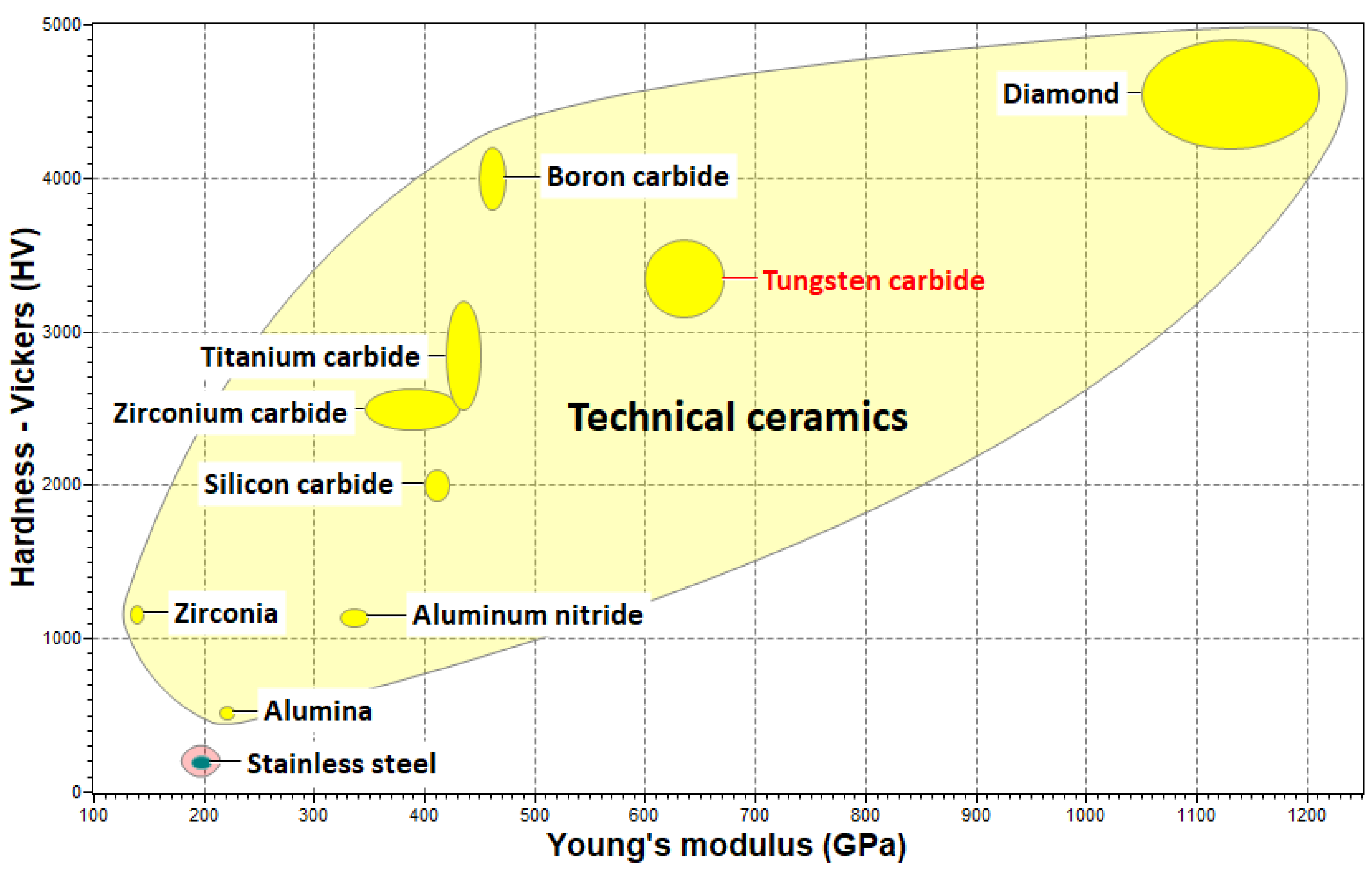
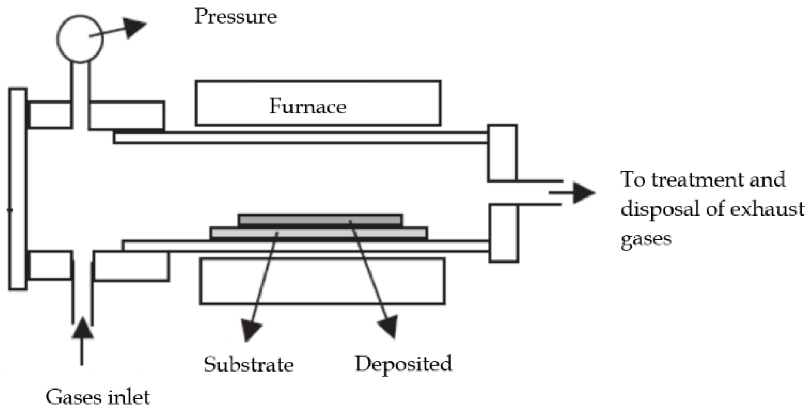
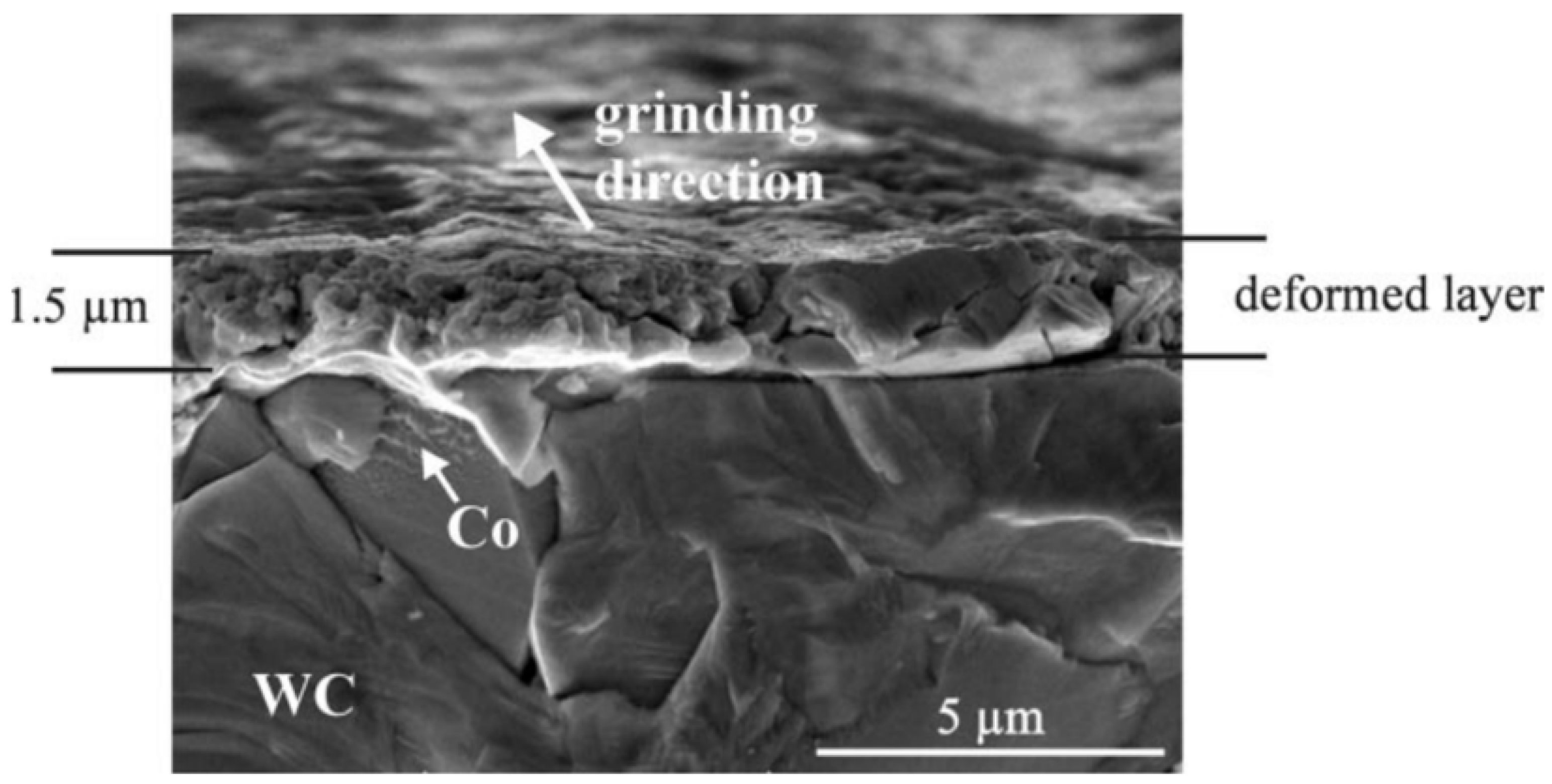
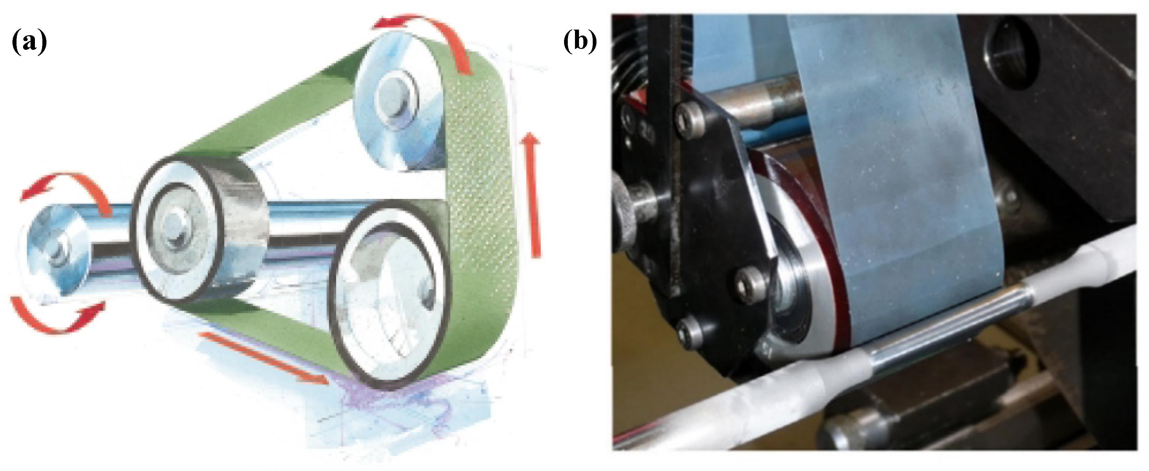
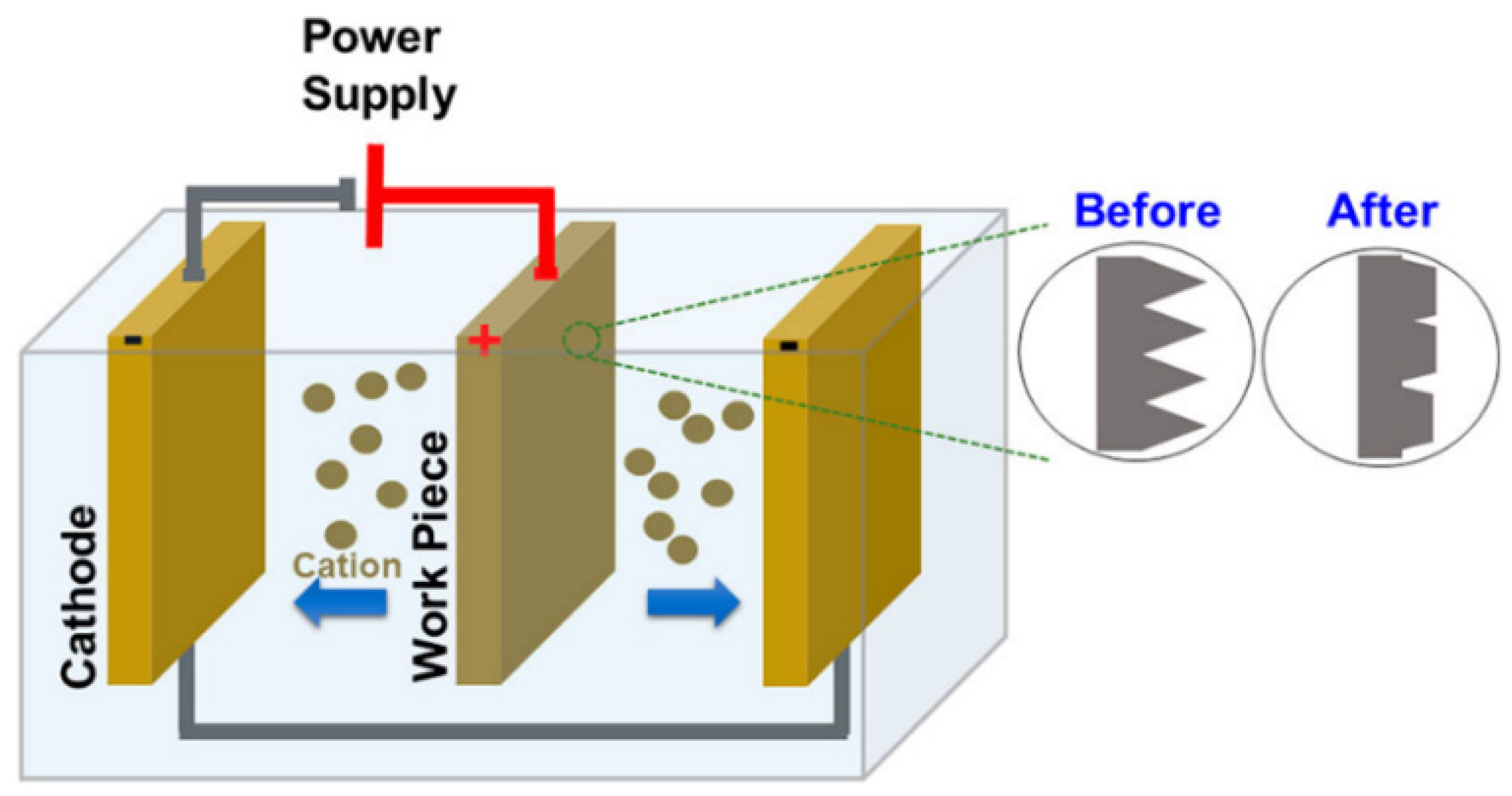
Table 1.
Strengths and limitations of coating deposition techniques used to deposit WC-based coatings.
Table 1.
Strengths and limitations of coating deposition techniques used to deposit WC-based coatings.
| Deposition Techniques | Strengths | Limitations |
|---|---|---|
| Electrodeposition |
|
|
| Magnetron sputtering |
|
|
| Thermal spray |
|
|
| CVD |
|
|
Table 2.
Film characteristics and typical deposition method of widely available WC-based and comparable hard coatings.
Table 2.
Film characteristics and typical deposition method of widely available WC-based and comparable hard coatings.
| Coatings | Deposition Method | Hardness (Hv) | Thickness (µm) | Porosity (%) | Ref |
|---|---|---|---|---|---|
| WC-Based Coatings | |||||
| WC/W | CVD | 800–1600 | 5–200 | <0.5 | [43] |
| WC/C | PVD | 1500–1800 | 2–4 | – | [17] |
| WC–10Co–4C | Thermal spray HVOF | 1279 | 180–200 | 3.5 | [45] |
| Ni/WC | Electrodeposition | 522 | 15 | – | [26] |
| WC-DLC | HiPIMS | 1886–4089 | 5.7–8 | – | [33] |
| Other Hard Coatings | |||||
| Hard Chrome | Electrodeposition | 600–1200 | 50–150 | <0.5 | [46] |
| Al2O3 | RF Plasma spray | 980–1110 | ~ 300 | <6 | [47] |
| CrC/C | Sputtering PVD | 1500 | 1.5–2 | – | [48] |
| cBN | Sputtering PVD | >6000 | 1.5–2 | – | [49] |
| VC | Thermo-Reactive Deposition (TRD) | 2430–2700 | 1–12 | – | [50] |
| a-SiC:H | PECVD | >2300 | 3 | – | [51] |
| TiN | PVD | <2090 | 8 | – | [52] |
Table 3.
Key strengths and limitations for contact and non-contact surface finishing techniques on WC coatings.
Table 3.
Key strengths and limitations for contact and non-contact surface finishing techniques on WC coatings.
| Techniques | Strengths | Limitations | |
|---|---|---|---|
| Contact Techniques | Diamond Turning |
|
|
| Precision Grinding |
|
| |
| Superfinishing |
|
| |
| Vibratory Polishing |
|
| |
| Non-contact Techniques | Electrical Discharge Machining |
|
|
| Electropolishing |
|
|
© 2020 by the authors. Licensee MDPI, Basel, Switzerland. This article is an open access article distributed under the terms and conditions of the Creative Commons Attribution (CC BY) license (http://creativecommons.org/licenses/by/4.0/).
Share and Cite
MDPI and ACS Style
Micallef, C.; Zhuk, Y.; Aria, A.I. Recent Progress in Precision Machining and Surface Finishing of Tungsten Carbide Hard Composite Coatings. Coatings 2020, 10, 731. https://doi.org/10.3390/coatings10080731
AMA Style
Micallef C, Zhuk Y, Aria AI. Recent Progress in Precision Machining and Surface Finishing of Tungsten Carbide Hard Composite Coatings. Coatings. 2020; 10(8):731. https://doi.org/10.3390/coatings10080731
Chicago/Turabian StyleMicallef, Christian, Yuri Zhuk, and Adrianus Indrat Aria. 2020. "Recent Progress in Precision Machining and Surface Finishing of Tungsten Carbide Hard Composite Coatings" Coatings 10, no. 8: 731. https://doi.org/10.3390/coatings10080731
Note that from the first issue of 2016, this journal uses article numbers instead of page numbers. See further details here.