
Seismic Retrofitting of Mid-Rise Unreinforced Masonry Residential Buildings after the 2010 Kraljevo, Serbia Earthquake: A Case Study

Abstract
:1. Introduction
2. Design Code Requirements for Seismic Retrofitting of Masonry Buildings from the Serbian Code and Eurocode 8, Part 3
3. Seismic Retrofitting Techniques for URM Buildings
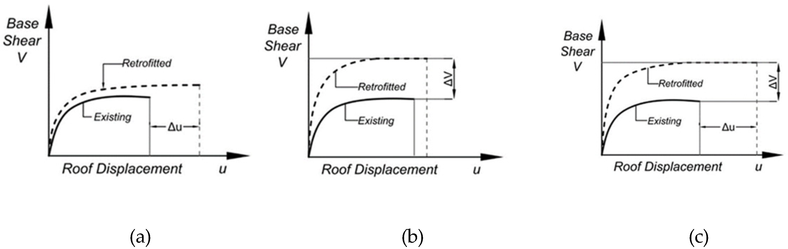
3.1. Seismic Retrofitting Objectives
3.2. Seismic Retrofitting Techniques—An Overview
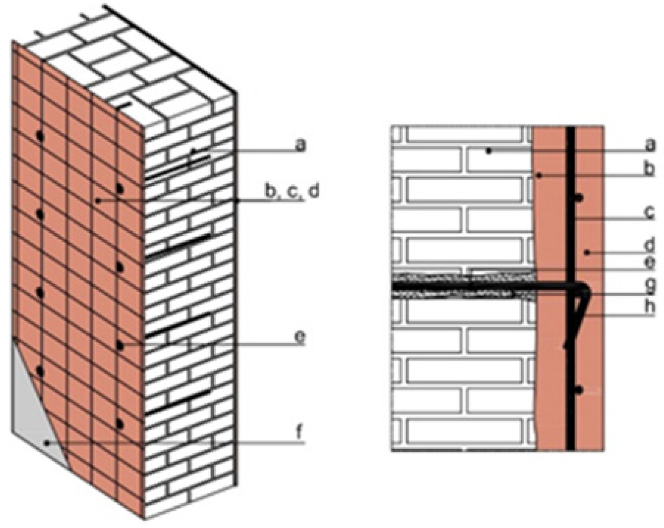
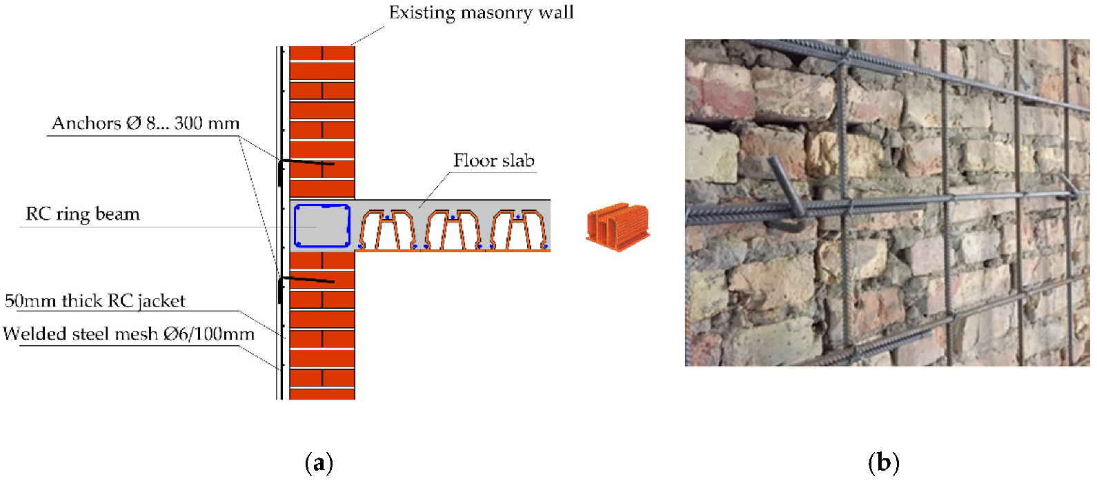
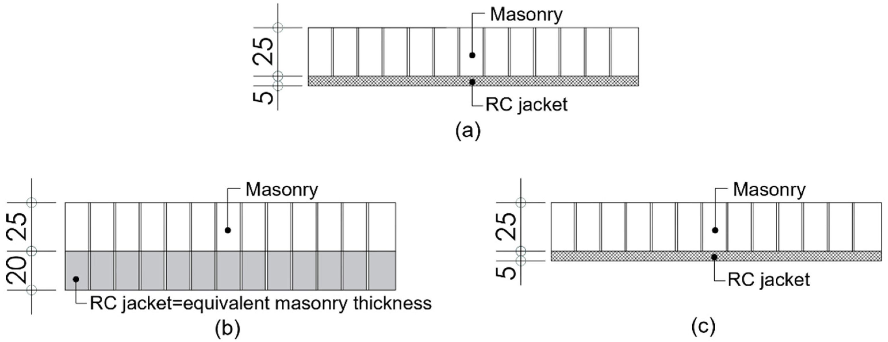
3.3. RC Jacketing—A Wall Retrofitting Technique
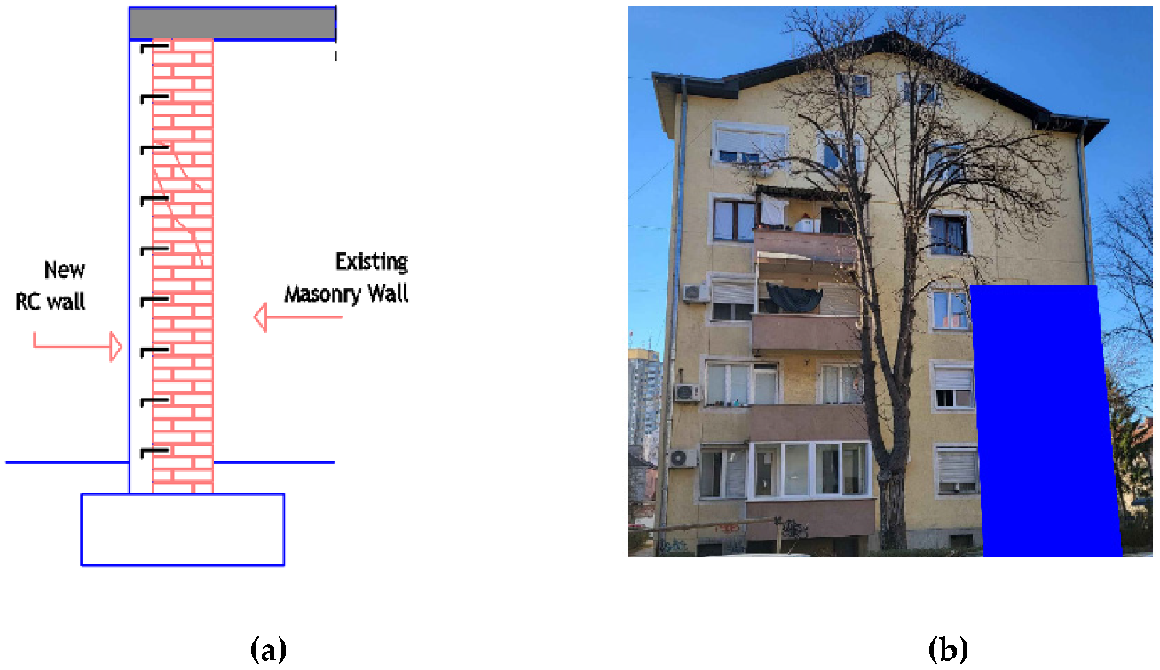
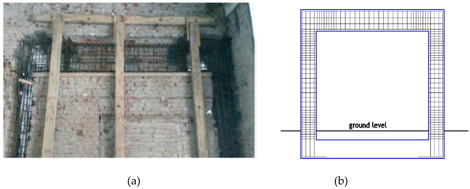
3.4. A New RC Overlay/Wall Attached to the Existing One—A Wall Retrofitting Technique
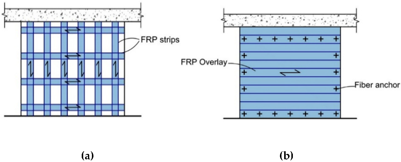
3.5. FRP Overlays or Strips—A Wall Retrofitting Technique
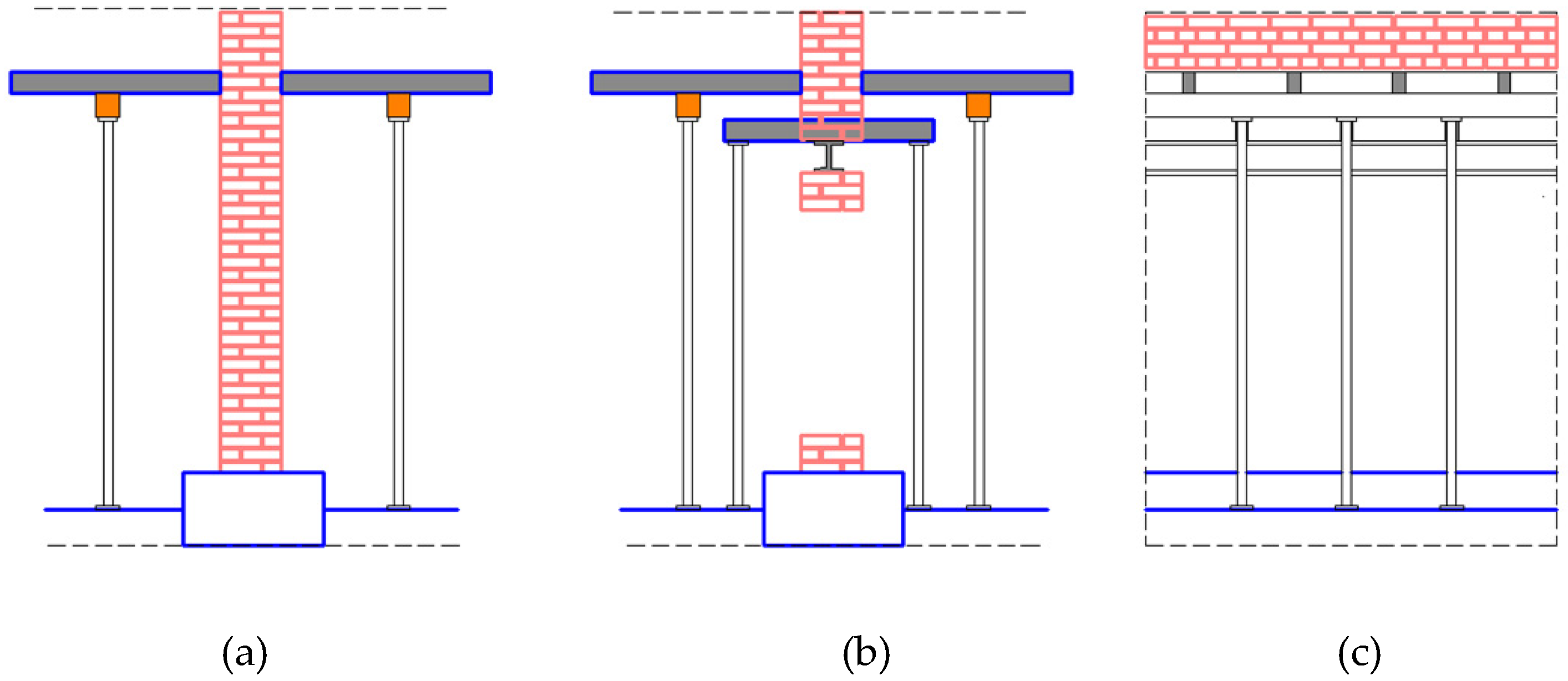
3.6. Replacement of Existing Masonry Walls
3.7. Retrofitting of Flexible Floor Structures
3.8. Comparison of Seismic Retrofitting Techniques for Masonry Buildings
4. Seismic Retrofitting of Damaged URM Buildings after the 2010 Kraljevo Earthquake: A Case Study
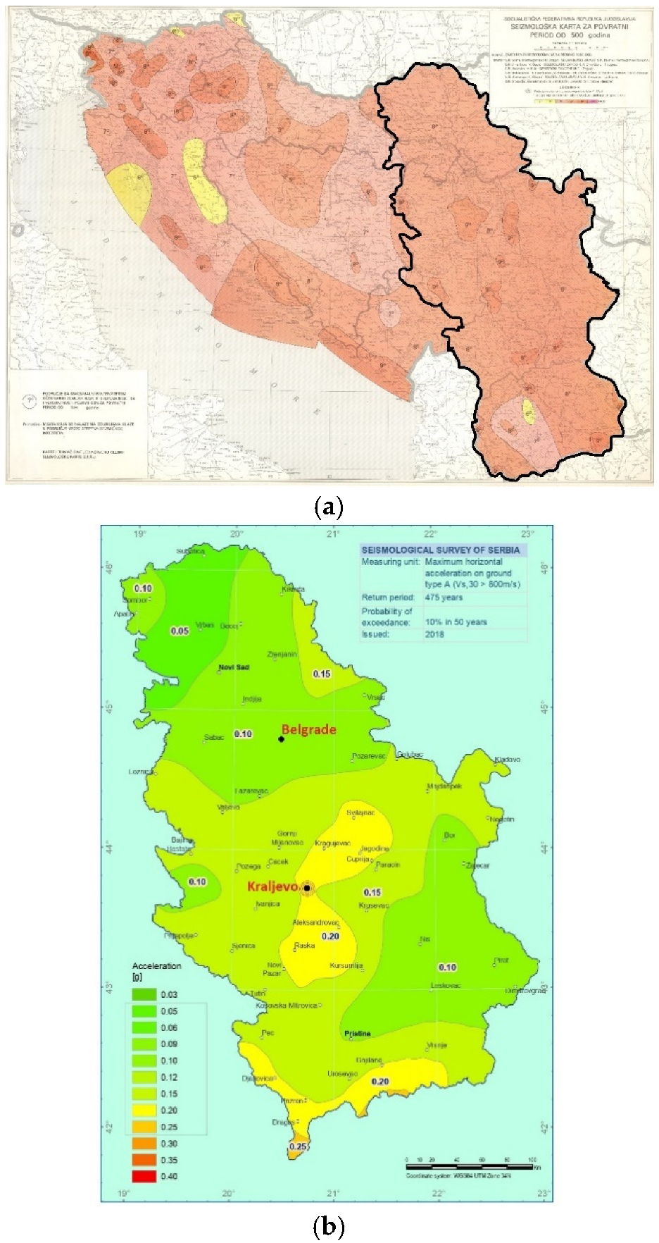
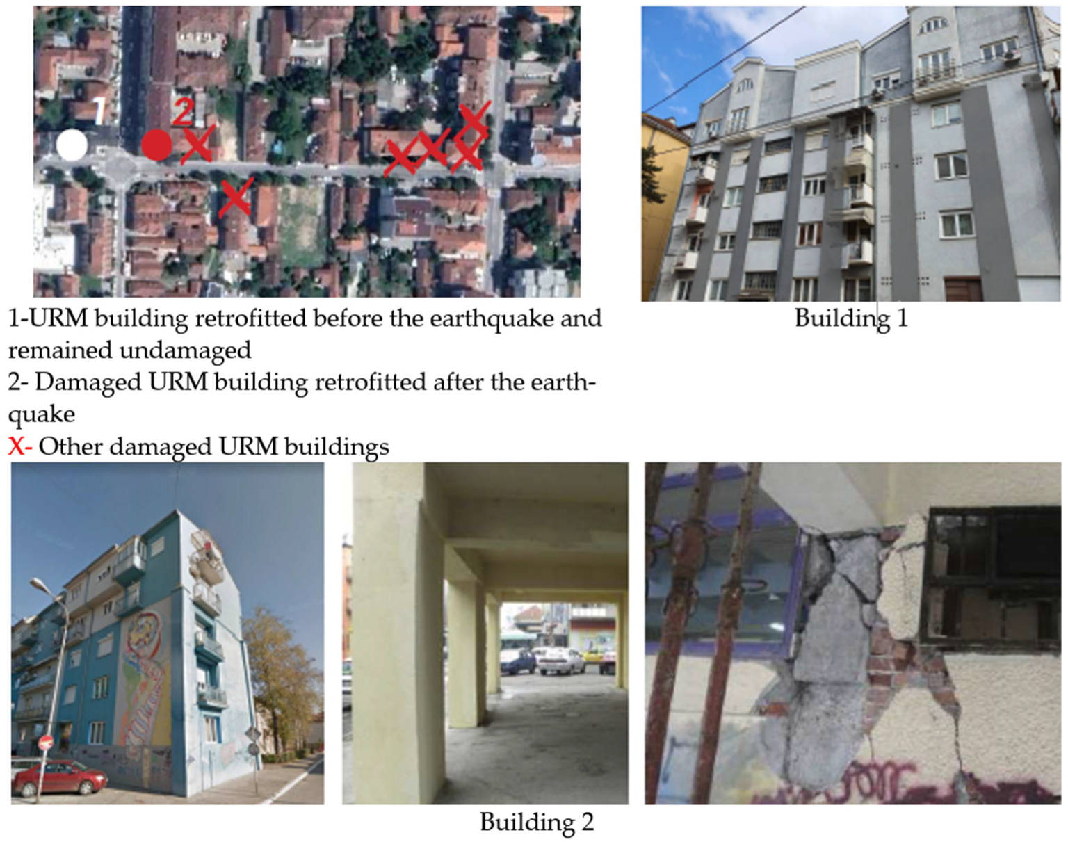
4.1. The Earthquake and Its Consequences
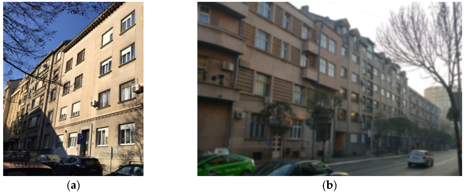
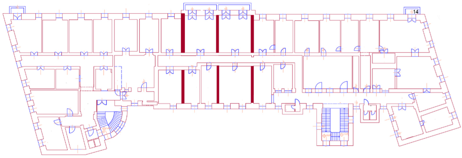
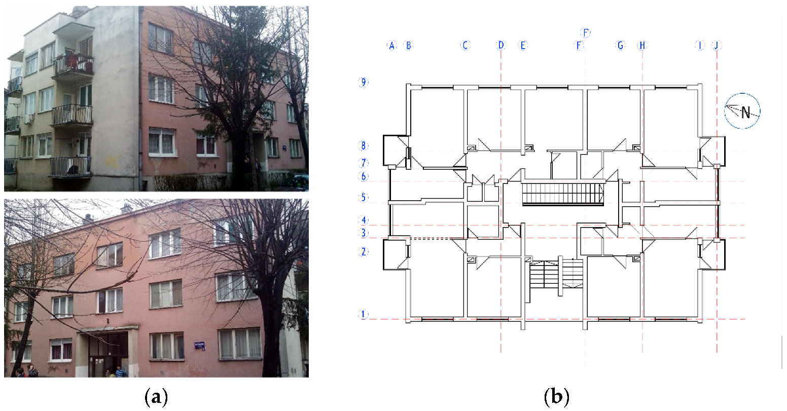
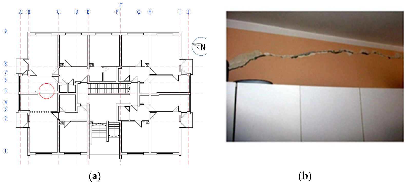
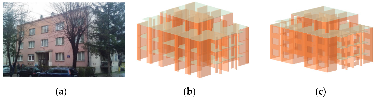
4.2. Case Study Building: Description and Earthquake Damage
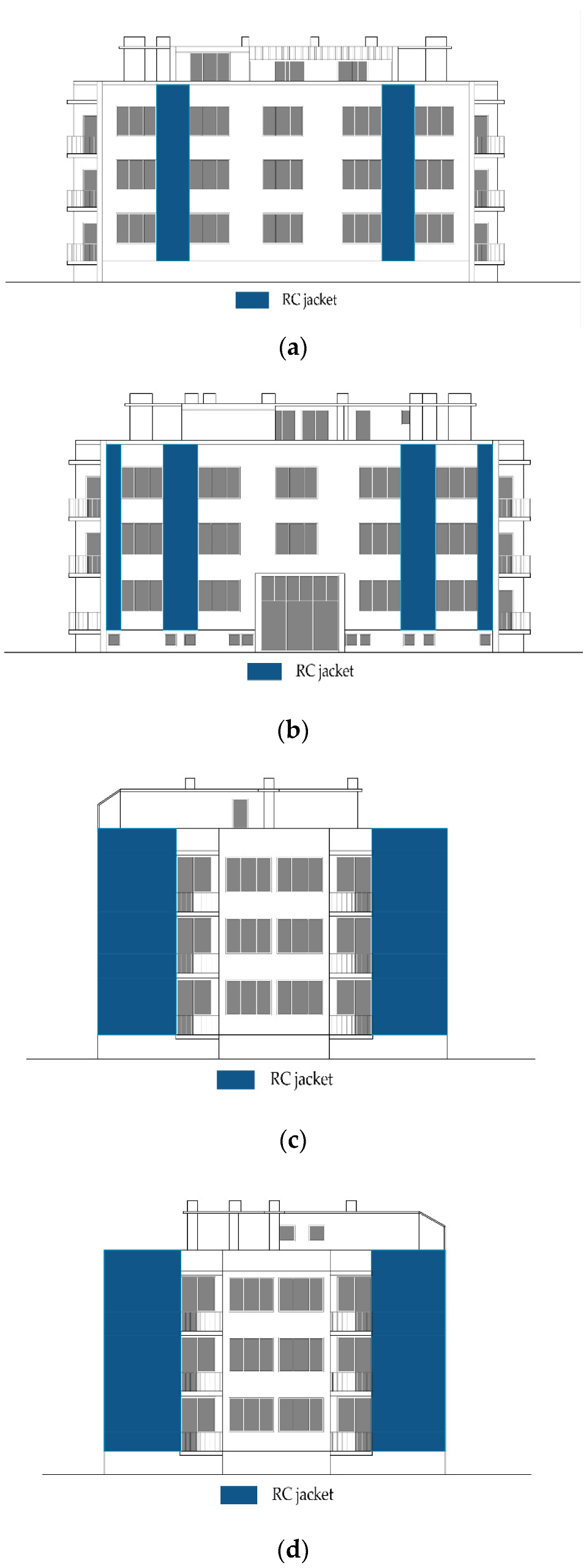
4.3. Seismic Retrofitting Approach
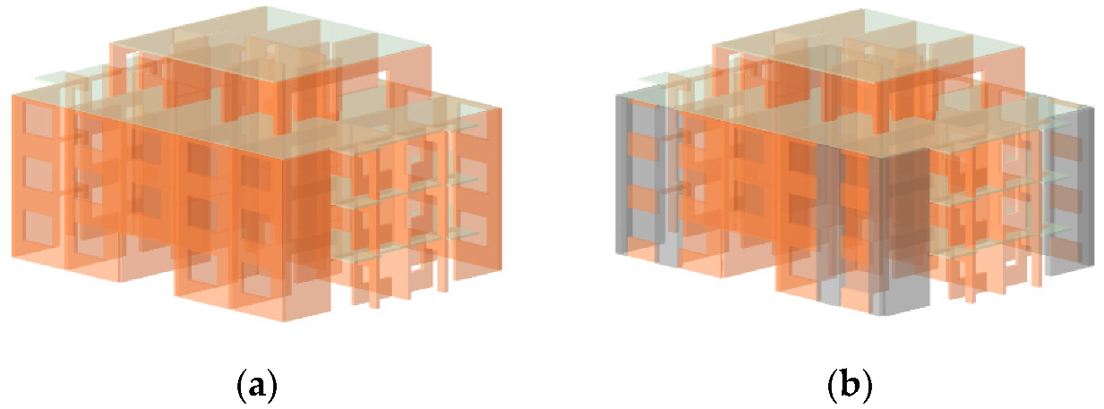
4.4. Seismic Analysis and Numerical Models
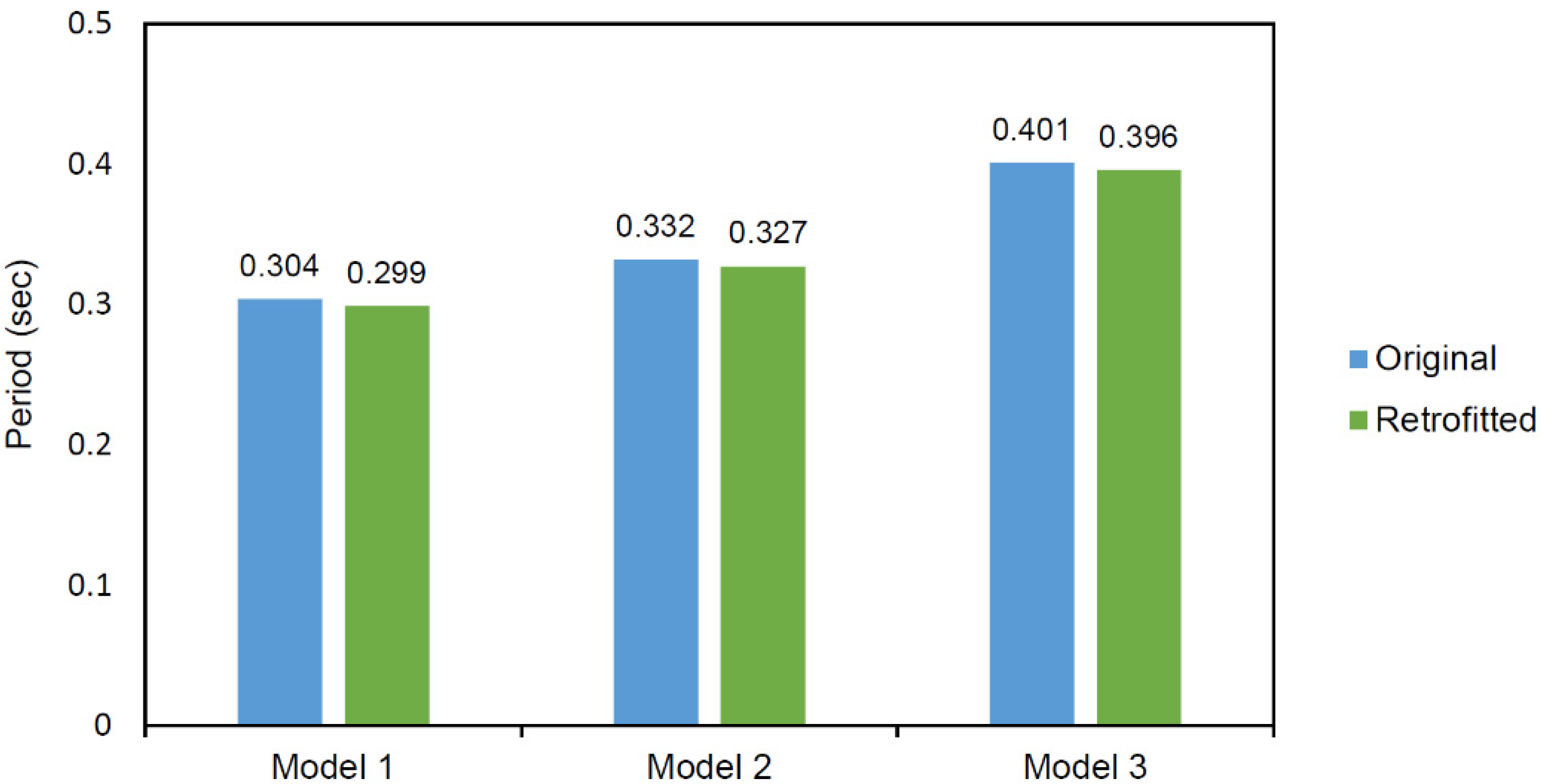
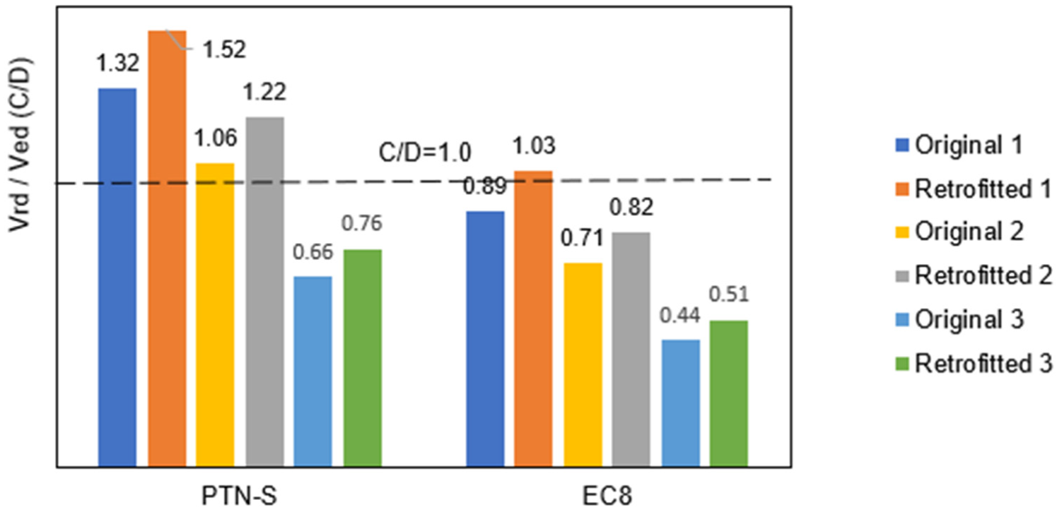
4.5. Results and Discussion
4.6. Limitations of the Study: Seismic Analysis Procedure
5. Conclusions
6. Recommendations for Future Research Studies
Author Contributions
Funding
Data Availability Statement
Acknowledgments
Conflicts of Interest
References
- Brzev, S.; Blagojević, P.; Cvetković, R. Simplified seismic assessment of unreinforced masonry residential buildings in the Balkans: The case of Serbia. Buildings 2021, 11, 392. [Google Scholar]
- Statistical Office of the Republic of Serbia (SORS). Number and the floor space of housing units and dwellings according to the occupancy status, by settlements. In The Census of Population, Households and Dwellings; Statistical Office of the Republic of Serbia, Belgrade, Serbia: 2011. Available online: https://www.stat.gov.rs/sr-latn/oblasti/popis/popis-2011/popisni-podaci-eksel-tabele/ (accessed on 10 December 2022).
- Atalić, J.; Uroš, M.; Šavor Novak, M.; Demšić, M.; Nastev, M. The Mw5.4 Zagreb (Croatia) earthquake of March 22, 2020: Impacts and response. Bull. Earthq. Eng. 2021, 19, 3461–3489. [Google Scholar] [CrossRef] [PubMed]
- Stepinac, M.; Lourenço, P.B.; Atalić, J.; Kišiček, T.; Uroš, M.; Baniček, M.; Šavor Novak, M. Damage classification of residential buildings in historical downtown after the ML5.5 earthquake in Zagreb, Croatia in 2020. Int. J. Disaster Risk Reduct. 2021, 56, 102140. [Google Scholar] [CrossRef]
- Miranda, E.; Brzev, S.; Bijelić, N. Petrinja, Croatia December 29, 2020, Mw 6.4 Earthquake. StEER-EERI Joint Reconnaissance Report, 2021. Available online: https://www.designsafe-ci.org/data/browser/public/designsafe.storage.published/PRJ-2959 (accessed on 15 December 2022).
- Tomaževič, M.; Weiss, P. Seismic behavior of plain- and reinforced-masonry buildings. J. Struct. Eng. 1994, 120, 323–338. [Google Scholar] [CrossRef]
- Andonov, A.; Baballëku, M.; Baltzopoulos, G.; Blagojević, N.; Bothara, J.; Brûlé, S.; Brzev, S.; Veliu, E. EERI Earthquake Reconnaissance Team Report: M6.4 Albania Earthquake on 26 November 2019; Earthquake Engineering Research Institute: Oakland, CA, USA, 2022; Available online: http://www.learningfromearthquakes.org/images/earthquakes/2019_Albania_Earthquake/EERI_Earthquake_Reconnaissance_Report_-_M6.4_Albania_Earthquake_on_November_26_2019.pdf (accessed on 20 December 2022).
- Tomaževič, M.; Klemenc, I.; Weiss, P. Seismic upgrading of old masonry buildings by seismic isolation and CFRP laminates: A shaking-table study of reduced scale models. Bull. Earthq. Eng. 2009, 7, 293–321. [Google Scholar] [CrossRef]
- Ademovic, N.; Hrasnica, M.; Oliveira, D.V. Pushover analysis and failure pattern of a typical masonry residential building in Bosnia and Herzegovina. Eng. Struct. 2013, 50, 13–29. [Google Scholar] [CrossRef] [Green Version]
- Ademović, N.; Oliveira, D.V.; Lourenço, P.B. Seismic evaluation and strengthening of an existing masonry building in Sarajevo, B&H. Buildings 2019, 9, 30. [Google Scholar]
- Grünthal, G. European Macroseismic Scale 1998; Centre Europèen de Géodynamique et de Séismologie: Luxembourg, 1998; Volume 15, ISBN 2879770084. [Google Scholar]
- Blagojević, N.; Brzev, S.; Petrović, M.; Borozan, J.; Bulajić, B.; Marinković, M.; Hadzima-Nyarko, M.; Koković, V.; Stojadinović, B. Residential building stock in Serbia: Classification and vulnerability for seismic risk studies. Bull. Earthq. Eng. 2023, under review. [Google Scholar]
- Berg, G.V. The Skopje, Yugoslavia Earthquake July 26, 1963; American Iron & Steel Institute: Washington, DC, USA, 1964. [Google Scholar]
- Manić, M.; Bulajić, B. Ponašanje zidanih zgrada u kraljevačkom zemljotresu od 03. novembra 2010. godine—Iskustva i pouke (Behaviour of masonry buildings during the November 03, 2010 Kraljevo earthquake). Izgradnja 2013, 67, 235–246. (In Serbian) [Google Scholar]
- PTP-12. Privremeni Tehnički Propisi za Građenje u Seizmičkim Područjima (Provisional Technical Regulations for Construction in Seismic Regions); Official Gazette of SFRY No. 39/64; Yugoslav Institute for Standardization: Belgrade, Yugoslavia, 1964. (In Serbian) [Google Scholar]
- PTN-S. Pravilnik o Tehničkim Normativima za Izgradnju Objekata Visokogradnje u Seizmičkim Područjima (Technical Regulations for the Design and Construction of Buildings in Seismic Regions); Official Gazette of SFRY No. 31/81 (Amendments 49/82, 29/83, 21/88, 52/90); Yugoslav Institute for Standardization: Belgrade, Yugoslavia, 1981; Available online: https://iisee.kenken.go.jp/worldlist/64_Serbia/64_Serbia_Code.pdf (accessed on 13 December 2022).
- Fajfar, P. Analysis in seismic provisions for buildings: Past, present and future. The fifth Prof. Nicholas Ambraseys lecture. Bull. Earthq. Eng. 2018, 16, 2567–2608. [Google Scholar] [CrossRef] [Green Version]
- PGK. Pravilnik za Građevinske Konstrukcije (Building regulations); Official Gazette of Republic of Serbia No. 89/2019, 52/2020, 122/2020; Institute for Standardization of Serbia: Belgrade, Serbia, 2019. (In Serbian) [Google Scholar]
- EN 1998-1:2005. Eurocode 8—Design of Structures for Earthquake Resistance-Part 1: General Rules, Seismic Actions and Rules for Buildings. European Committee for Standardization: Bruxelles, Belgium, 2005.
- SRPS EN 1998-1/NA:2018. Evrokod 8—Projektovanje Seizmički Otpornih Konstrukcija Deo 1: Opsta Pravila, Seizmicka Dejstva i Pravila za Zgrade (Eurocode 8—Design of Structures for Earthquake Resistance-Part 1: General Rules, Seismic Actions and Rules for Buildings). Institute for Standardization of Serbia: Belgrade, Serbia, 2018. (In Serbian)
- EN 1998-3:2005. Eurocode 8—Design of Structures for Earthquake Resistance-Part 3: Assessment and Retrofitting of Buildings. European Committee for Standardization: Bruxelles, Belgium, 2005.
- SRPS EN 1998-3/NA:2018. Evrokod 8—Projektovanje seizmički otpornih konstrukcija Deo 3: Evaluacija i ojačanje konstrukcija (Eurocode 8—Design of structures for earthquake resistance-Part 3: Assessment and retrofitting of buildings, EN 1998-3:2005). Institute for Standardization of Serbia: Belgrade, Serbia, 2018. (In Serbian)
- Seismological Survey of Serbia (SSS). Seismic Hazard Maps for Serbia; Seismological Survey of Serbia: Belgrade, Serbia, 2018. Available online: http://www.seismo.gov.rs/Seizmicnost/Karte_hazarda_e.htm (accessed on 10 December 2022).
- PTN-R. Pravilnik o Tehničkim Normativima za Sanaciju, Ojačanje i Rekonstrukciju Objekata Visokogradnje Oštećenih Zemljotresom i za Rekonstrukciju i Revitalizaciju Objekata Visokogradnje (Technical Regulations for Repair, Strengthening and Reconstruction of Building Structures Damaged by Earthquakes and for Reconstruction and Rehabilitation of Buildings); Službeni list SFRJ No. 52/85; Yugoslavia, 1985. (In Serbian) [Google Scholar]
- PTN-Z. Pravilnik o Tehničkim Normativima za Zidane Zidove (Technical Norms Regulation for Masonry Walls); Official Gazette of SFRY No. 87/91; Yugoslav Institute for Standardization: Belgrade, Yugoslavia, 1991. (In Serbian) [Google Scholar]
- EN 1996-1-1:2004. Eurocode 6—Design of Masonry Structures. Part 1-1: General rules for reinforced and unreinforced masonry structures. European Committee for Standardization: Bruxelles, Belgium, 2004.
- ASCE/SEI. Seismic Evaluation and Retrofit of Existing Buildings, Standard (ASCE/SEI 41-17); American Society of Civil Engineers/Structural Engineering Institute: Reston, VA, USA, 2017. [Google Scholar]
- Thermou, G.E.; Elnashai, A.S. Seismic retrofit schemes for rc structures and local–global consequences. Prog. Struct. Eng. Mater. 2006, 8, 1–15. [Google Scholar] [CrossRef]
- Thermou, G.E.; Pantazopoulou, S.J.; Elnashai, A.S. Upgrading of RC Structures for a target response shape. In Proceedings of the 13th World Conference on Earthquake Engineering, Vancouver, BC, Canada, 1–6 June 2004. [Google Scholar]
- Brzev, S.; Begaliev, U. Practical Seismic Design and Construction Manual for Retrofitting Schools in the Kyrgyz Republic; World Bank group: Washington, DC, USA, 2018; pp. 1–251. Available online: http://documents.worldbank.org/curated/en/505451593451983935/Practical-Seismic-Design-and-Construction-Manual-for-Retrofitting-Schools-in-The-Kyrgyz-Republic (accessed on 15 December 2022).
- Salaman, A.; Stepinac, M.; Matorić, I.; Klasić, M. Post-earthquake condition assessment and seismic upgrading strategies for a heritage-protected school in Petrinja, Croatia. Buildings 2022, 12, 2263. [Google Scholar] [CrossRef]
- Triller, P.; Tomaževič, M.; Lutman, M.; Gams, M. Seismic behavior of strengthened URM masonry—An overview of research at ZAG. International Conference on Analytical Models and New Concepts in Concrete and Masonry Structures AMCM’2017. Procedia Eng. 2017, 193, 66–73. [Google Scholar] [CrossRef]
- Abrams, D.; Smith, T.; Lynch, J.; Franklin, S. Effectiveness of rehabilitation on seismic behavior of masonry piers. J. Struct. Eng. 2007, 133, 32–43. [Google Scholar] [CrossRef]
- Marinković, M.; Baballëku, M.; Isufi, B.; Blagojević, N.; Milićević, I.; Brzev, S. Performance of RC cast-in-place buildings during the November 26, 2019 Albania earthquake. Bull. Earthq. Eng. 2022, 20, 5427–5480. [Google Scholar] [CrossRef]
- Gkournelos, P.D.; Triantafillou, T.C.; Bournas, D.A. Seismic upgrading of existing reinforced concrete buildings: A state-of-the-art review. Eng. Struct. 2021, 240, 112273. [Google Scholar] [CrossRef]
- Wararuksajja, W.; Leelataviwat, S.; Warnitchai, P.; Bing, L.; Tariq, H.; Naiyana, N. Seismic strengthening of soft-story RC moment frames. In Proceedings of the 25th National Convention on Civil Engineering, Chonburi, Thailand, 9 July 2020. [Google Scholar]
- UNIDO. Building Construction Under Seismic Conditions in the Balkan Region: Repair and Strengthening of Reinforced Concrete, Stone and Brick Masonry Buildings, 1st ed.; United Nations Industrial Development Programme: Vienna, Austria, 1983; Volume 5, 231p. [Google Scholar]
- Tomaževič, M. Earthquake-Resistant Design of Masonry Buildings; Imperial College Press: London, UK, 1999; 268p. [Google Scholar]
- Uroš, M.; Todorić, M.; Crnogorac, M.; Atalić, J.; Šavor Novak, M.; Lakušić, S. (Eds.) Potresno Inženjerstvo—Obnova Zidanih Zgrada; Građevinski fakultet, Sveučilišta u Zagrebu: Zagreb, Croatia, 2021; ISBN 978-953-8163-43-7. [Google Scholar]
- Muravljov, M.; Stevanović, B.; Ostojić, D. Sanacije Građevinskih Konstrukcija i Objekata, 1st ed.; Faculty of Civil Engineering, University of Belgrade: Belgrade, Serbia, 2022; pp. 1–271. (In Serbian) [Google Scholar]
- Churilov, S.; Dumova-Jovanoska, E. Analysis of masonry walls strengthened with RC jackets. In Proceedings of the 15th World Conference on Earthquake Engineering, Lisbon, Portugal, 24–28 September 2012. [Google Scholar]
- Ostojić, D.; Stevanović, B.; Muravljov, M.; Glišović, I. Sanacija i ojačanje zidanih objekata oštećenih zemljotresom u Kraljevu. In Proceedings of the 4th International Conference, Civil engineering—Science and practice, Žabljak, Montenegro, 20–24 February 2012. (In Serbian). [Google Scholar]
- Medić, S.; Hrasnica, M. In-plane seismic response of unreinforced and jacketed masonry walls. Buildings 2021, 11, 472. [Google Scholar] [CrossRef]
- El Gawady, M.; Lestuzzi, P.; Badoux, M. Retrofitting of masonry walls using shotcrete. In Proceedings of the 2006 NZSEE Conference, Napier, New Zealand, 10–12 March 2006. [Google Scholar]
- Sheppard, P.; Terčelj, S. The effect of repair and strengthening methods for masonry walls. In Proceedings of the 7th World Conference on Earthquake Engineering, Istanbul, Turkey, 8–13 September 1980. [Google Scholar]
- Proença, J.M.; Gago, A.S.; Costa, A.V.; André, A.M. Strengthening of masonry wall load bearing structures with reinforced plastering mortar solution. In Proceedings of the 15th World Conference on Earthquake Engineering, Lisbon, Portugal, 24–28 September 2012. [Google Scholar]
- Kadam, S.B.; Singh, Y.; Li, B. Strengthening of unreinforced masonry using welded wire mesh and micro-concrete—behaviour under in-plane action. Constr. Build. Mater. 2014, 54, 247–257. [Google Scholar] [CrossRef]
- Lin, Y.; Biggs, D.; Wotherspoon, L.; Ingham, J.M. In-plane strengthening of unreinforced concrete masonry wallettes using ECC shotcrete. J. Struct. Eng. 2014, 140, 04014081. [Google Scholar] [CrossRef]
- Jurukovski, D.; Krstevska, L.; Alessi, R.; Diotallevi, P.P.; Merli, M.; Zarri, F. Shaking table tests of three four-storey brick masonry models: Original and strengthened by RC core and RC jackets. In Proceedings of the 10th World Conference on Earthquake Engineering, Madrid, Spain, 19–24 July 1992. [Google Scholar]
- Hutchison, D.; Yong, P.; McKenzie, G. Laboratory testing of a variety of strengthening solutions for brick masonry wall panels. In Proceedings of the 8th World Conference on Earthquake Engineering, San Francisco, CA, USA, 21–28 July 1984. [Google Scholar]
- FEMA. Techniques for the Seismic Rehabilitation of Existing Buildings; FEMA 547; Federal Emergency Management Agency: Washington, DC, USA, 2006; 571p. [Google Scholar]
- INRC. Guide for the Design and Construction of Externally Bonded FRP Systems for Strengthening Existing Structures: Materials, RC and PC structures, Masonry Structures; CNR-DT 200 R1/2013; Italian National Research Council, Advisory Committee on Technical Recommendations for Construction: Rome, Italy, 2014; 154p. [Google Scholar]
- Ehsani, M.R.; Saadatmanesh, H.; Al-Saidy, A. Shear behavior of URM retrofitted with FRP overlays. J. Compos. Constr. ASCE 1997, 1, 17–25. [Google Scholar] [CrossRef]
- Reinhorn, A.M.; Madan, A. Evaluation of Tyfo-W Fiber Wrap System for In-Plane Strengthening of Masonry Walls; Report No. 95-0002; Department of Civil Engineering, State University of New York at Buffalo: Buffalo, NY, USA, 1995. [Google Scholar]
- ElGawady, M.; Lestuzzi, P.; Badoux, M. Static cyclic response of masonry walls retrofitted with fiber-reinforced polymers. J. Compos. Constr. 2007, 11, 50–61. [Google Scholar] [CrossRef]
- Tomaževič, M.; Gams, M.; Berset, T. Seismic strengthening of brick masonry walls with composites: An experimental study. In Proceedings of the Structural Engineers World Congress, Villa Erba, Como, Italy, 4–6 April 2011. [Google Scholar]
- Arifuzzaman, S.; Saatcioglu, M. Seismic retrofit of load bearing masonry walls by FRP sheets and anchors. In Proceedings of the 15th World Conference on Earthquake Engineering, Lisbon, Portugal, 24–28 September 2012. [Google Scholar]
- Paquette, J.; Bruneau, M.; Brzev, S. Seismic testing of repaired unreinforced masonry building having flexible diaphragm. J. Struct. Eng. ASCE 2004, 130, 1487–1496. [Google Scholar] [CrossRef]
- ElGawady, M.; Lestuzzi, P.; Badoux, M. In-plane seismic response of unreinforced masonry walls upgraded with fiber reinforced polymer. J. Comp. for Constr. ASCE 2005, 9, 524–535. [Google Scholar] [CrossRef]
- ElGawady, M.; Lestuzzi, P.; Badoux, M. Aseismic retrofitting of unreinforced masonry walls using FRP. Compos. Part B 2006, 37, 148–162. [Google Scholar] [CrossRef]
- Turek, M.; Ventura, C.E.; Kuan, S. In-plane shake-table testing of GFRP strengthened concrete masonry walls. Earthq. Spectra 2007, 23, 223–237. [Google Scholar] [CrossRef]
- Kišiček, T.; Stepinac, M.; Renić, T.; Hafner, I.; Lulić, L. Strengthening of masonry walls with FRP or TRM. Građevinar 2020, 72, 937–953. [Google Scholar]
- Cvetković, R.; Stojić, D.; Marković, N.; Conić, S. Analiza seizmičke otpornosti i ojačanje zidane konstrukcije Biskupije u Pančevu. Zbornik radova desetog međunarodnog naučno–stručnog savetovanja “Ocena stanja, održavanje i sanacija građevinskih objekata i naselja”; Vršac, Serbia: 14-16 June 2017 (In Serbian).
- Seismological Survey of Serbia. Izveštaj o rezultatima i aktivnostima Republičkog seiz-mološkog zavoda posle zemljotresa kod Kraljeva 03.11.2010 u 01:56 (Report on the results and activites of the Seismological Survey of Serbia after the earthquake in Kraljevo 03.11.2010 at 01:56); Seismological Survey of Serbia: Belgrade, Serbia, 2010. (In Serbian) [Google Scholar]
- World Bank. Europe and Central Asia (ECA) Risk Profiles: Serbia; World Bank Group: Washington, DC, USA, 2017; Available online: https://www.gfdrr.org/en/publication/disaster-risk-profile-serbia (accessed on 10 December 2022).
- Marinković, D.; Stojadinović, Z.; Kovačević, M.; Stojadinović, B. 2010 Kraljevo earthquake recovery process metrics derived from recorded reconstruction data. In Proceedings of the 16th European Conference on Earthquake Engineering, Thessaloniki, Greece, 8–21 June 2018. [Google Scholar]
- Ostojić, D.; Muravljov, M.; Stevanović, B. Primeri sanacije višespratnih stambenih zidanih zgrada oštećenih zemljotresom u Kraljevu (Examples of housing rehabilitation multistory masonry buildings damaged in the earthquake in Kraljevo). Izgradnja 2011, 5–6, 315–325. (In Serbian) [Google Scholar]
- Nikić, M. Sanacija stambene zgrade u Kraljevu oštećene u zemljotresu 2010. godine. Zbornik radova devetog međunarodnog naučno–stručnog savetovanja “Ocena stanja, održavanje i sanacija građevinskih objekata i naselja”, Zlatibor, Serbia, 25-29 May 2015. (In Serbian). [Google Scholar]
- Manić, M.; Bulajić, B. Zašto procena šteta na građevinskim objektima u kraljevačkom regionu nije izvršena ni godinu dana nakon zemljotresa od 03.11.2010. godine? Izgradnja 2012, 66, 269–308. (In Serbian) [Google Scholar]
- SRPS EN 1996-1-1:2016. Evrokod 6—Projektovanje Zidanih Konstrukcija Deo 1-1: Opsta Pravila za Armirane i Nearmirane zidane Konstrukcije (Eurocode 6—Design of Masonry Structures. Part 1-1: General Rules for Reinforced and Unreinforced Masonry Structures). Serbian Institute for Standardization: Belgrade, Serbia, 2016. (In Serbian)
- Radimpex. Tower—3D Model Builder 8.4-x64 Edition; Radimpex Software d.o.o: Belgrade, Serbia, 2022. [Google Scholar]
- Lagomarsino, S.; Penna, A.; Galasco, A.; Cattari, S. TREMURI program: An equivalent frame model for the nonlinear seismic analysis of masonry buildings. Eng. Struct. 2013, 56, 1787–1799. [Google Scholar] [CrossRef]
- Cattari, S.; Lagomarsino, S. Modelling the seismic response of unreinforced existing masonry buildings: A critical review of some models proposed by codes. In Proceedings of the 11th Canadian Masonry Symposium, Toronto, Canada, 31 May–3 June 2009. [Google Scholar]
- Federal Emergency Management Agency. Pre-Standard and Commentary for the Seismic Rehabilitation of Buildings; FEMA 356: Washington, DC, USA, 2000. [Google Scholar]
- Tomaževič, M. Dynamic modelling of masonry buildings: Storey mechanism model as a simple alternative. Earthq. Eng. Struct. Dyn. 1987, 15, 731–749. [Google Scholar] [CrossRef]
- Lourenço, P.B. Computational Strategy for Masonry Structures. Ph.D. Thesis, Delft University of Technology, Delft, The Netherlands, 1996. [Google Scholar]
- Magenes, G. A method for pushover analysis in seismic assessment of masonry buildings. In Proceedings of the 12th WCEE, Auckland, New Zealand, 30 January–4 February 2000. [Google Scholar]
- Galasco, A.; Lagomarsino, S.; Penna, A.; Resemini, S. Non-linear seismic analysis of masonry structures. In Proceedings of the 13th World Conference on Earthquake Engineering, Vancouver, Canada, 1–6 August 2004. [Google Scholar]
- Penna, A.; Lagomarsino, S.; Galasco, A. A nonlinear macro-element model for the seismic analysis of masonry buildings. Earthq. Eng. Struct. Dyn. 2013, 43, 159–179. [Google Scholar] [CrossRef]
- Crowley, H.; Dabbeek, J.; Despotaki, V.; Rodrigues, D.; Martins, L.; Silva, V.; Danciu, L. European Seismic Risk Model (ESRM20). EFEHR Technical Report 002, V1.0.1.; EUCENTRE Foundation: Pavia, Italy, 2021. [Google Scholar] [CrossRef]
- World Bank Group. Earthquake Risk in Multifamily Residential Buildings, Europe and Central Asia Region; World Bank Group: Washington, DC, USA, 2020. [Google Scholar]
- Rota, M.; Penna, A.; Strobbia, C.L. Processing Italian damage data to derive typological fragility curves. Soil Dyn. Earthq. Eng. 2008, 28, 933–947. [Google Scholar] [CrossRef]
- Del Gaudio, C.; De Martino, G.; Di Ludovico, M.; Manfredi, G.; Prota, A.; Ricci, P.; Verderame, G.M. Empirical fragility curves for masonry buildings after the 2009 L’Aquila, Italy, earthquake. Bull. Earthq. Eng. 2019, 17, 6301–6330. [Google Scholar] [CrossRef]
- Chieffo, N.; Clementi, F.; Formisano, A.; Lenci, S. Comparative fragility methods for seismic assessment of masonry buildings located in Muccia (Italy). J. Build. Eng. 2019, 25, 100813. [Google Scholar] [CrossRef]
- Stojadinović, Z.; Stojadinović, B.; Kovačević, M.; Marinković, D. Data-Driven Housing Damage and Repair Cost Prediction Framework Based on the 2010 Kraljevo Earthquake Data. In Proceedings of the 16th World Conference on Earthquake Engineering, Santiago, Chile, 9–13 January 2017. [Google Scholar]
- Ruggieri, S.; Calò, M.; Cardellicchio, A.; Uva, G. Analytical-mechanical based framework for seismic overall fragility analysis of existing RC buildings in town compartments. Bull. Earthq. Eng. 2022, 20, 8179–8216. [Google Scholar] [CrossRef]
- Predari, G.; Stefanini, L.; Marinković, M.; Stepinac, M.; Brzev, S. Adriseismic methodology for expeditious seismic assessment of unreinforced masonry buildings. Buildings 2023, accepted for publication. [Google Scholar] [CrossRef]
- Di Ludovico, M.; De Martino, G.; Prota, A.; Manfredi, G.; Dolce, M. Relationships between empirical damage and direct/indirect costs for the assessment of seismic loss scenarios. Bull. Earthq. Eng. 2022, 20, 229–254. [Google Scholar] [CrossRef]


| Retrofitting Technique | Advantages | Disadvantages | Local Availability of Construction Materials | Required Level of Construction Skills | Construction Cost | Disruption to the Occupants | Required Maintenance |
|---|---|---|---|---|---|---|---|
| (1) | (2) | (3) | (4) | (5) | (6) | (7) | (8) |
| RC jacketing | (i) One of the most cost-effective retrofitting techniques. (ii) Able to enhance flexural and/or shear capacity and/or ductility. | (i) Adds mass/weight to the structure. (ii) Drilling holes through the existing walls may be required. | High | Low | Low (approximately 99 EUR/m2 based on 5 cm thick RC jacket) | Moderate to high | Low |
| FRP overlays and strips | (i) Increases shear and/or flexural capacity of the existing wall. (ii) Lightweight. (iii) Rapid installation. | Requires fire and UV protection. | Low | Moderate to high | Moderate (approximately 110 EUR/m2 for CFRP strips) | Low | Low |
| Replacement of an existing masonry wall with a new masonry or RC shear wall | One of the most effective retrofitting techniques. | (i) May increase seismic forces at the wall-to-floor slab interface. (ii) Requires new foundations. (iii) Need to drill holes through the existing RC floor slabs. | High | Medium | Moderate | High | Low |
| Original 1 | Original 2 | Original 3 | ||||
|---|---|---|---|---|---|---|
| Cantilever Model | EFM | Cantilever Model | EFM | Cantilever Model | EFM | |
| N–S direction | 0.304 | 0.240 | 0.332 | 0.266 | 0.401 | 0.335 |
| E–W direction | 0.288 | 0.237 | 0.316 | 0.264 | 0.381 | 0.332 |
| Retrofitted 1 | Retrofitted 2 | Retrofitted 3 | ||||
|---|---|---|---|---|---|---|
| Cantilever Model | EFM | Cantilever Model | EFM | Cantilever Model | EFM | |
| N–S direction | 0.299 s | 0.231 s | 0.327 s | 0.258 s | 0.396 s | 0.326 s |
| E–W direction | 0.253 s | 0.227 s | 0.281 s | 0.253 s | 0.352 s | 0.319 s |
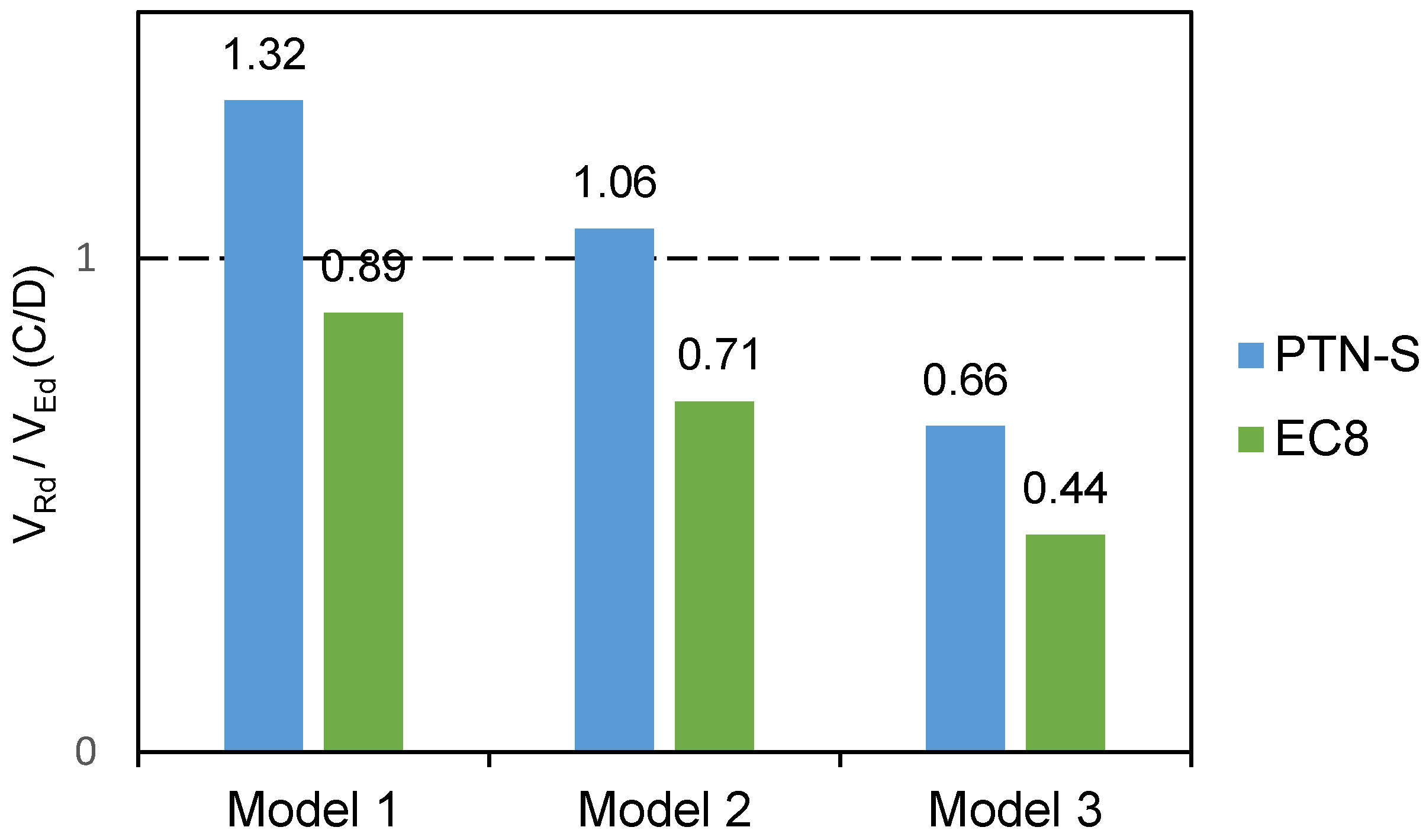
| Original 1 | Original 2 | Original 3 | ||||
|---|---|---|---|---|---|---|
| PTN-S | EC8 | PTN-S | EC8 | PTN-S | EC8 | |
| (1) | (2) | (3) | (4) | (5) | (6) | |
| C: Shear Capacity | 1231.57 | 2052.61 | 985.25 | 1642.09 | 615.78 | 1026.30 |
| D: Design Shear Force | 930.59 | 2301.70 | 930.59 | 2301.70 | 930.59 | 2301.70 |
| 1.32 | 0.89 | 1.06 | 0.71 | 0.66 | 0.44 | |
| Retrofitted 1 | Retrofitted 2 | Retrofitted 3 | ||||
|---|---|---|---|---|---|---|
| PTN-S | EC8 | PTN-S | EC8 | PTN-S | EC8 | |
| (1) | (2) | (3) | (4) | (5) | (6) | |
| C: Shear Capacity | 1477.88 | 2463.13 | 1180.08 | 1970.51 | 738.94 | 1231.56 |
| D: Design Shear Force | 969.88 | 2398.88 | 969.88 | 2398.88 | 969.88 | 2398.88 |
| 1.52 | 1.03 | 1.22 | 0.82 | 0.76 | 0.51 | |
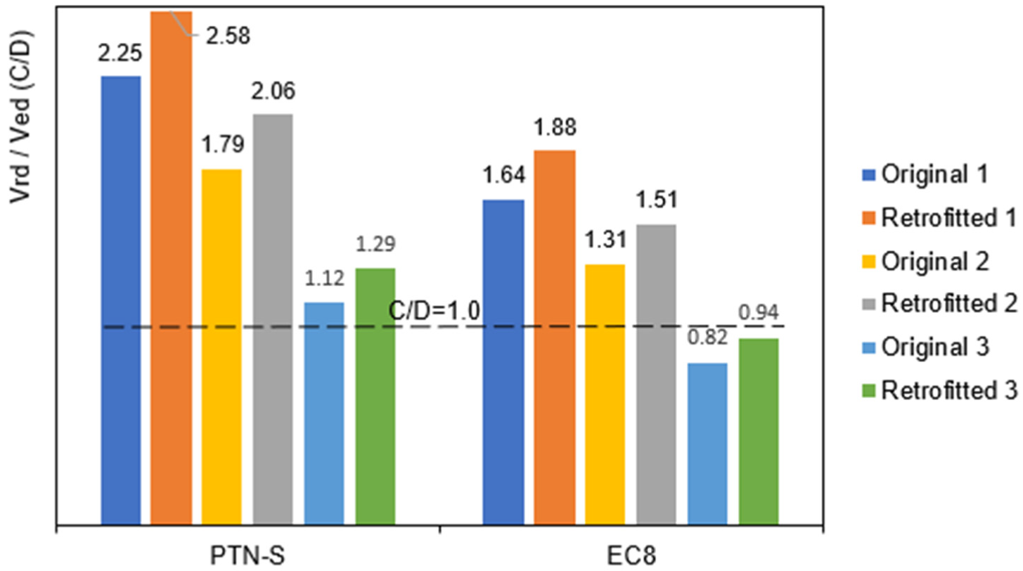
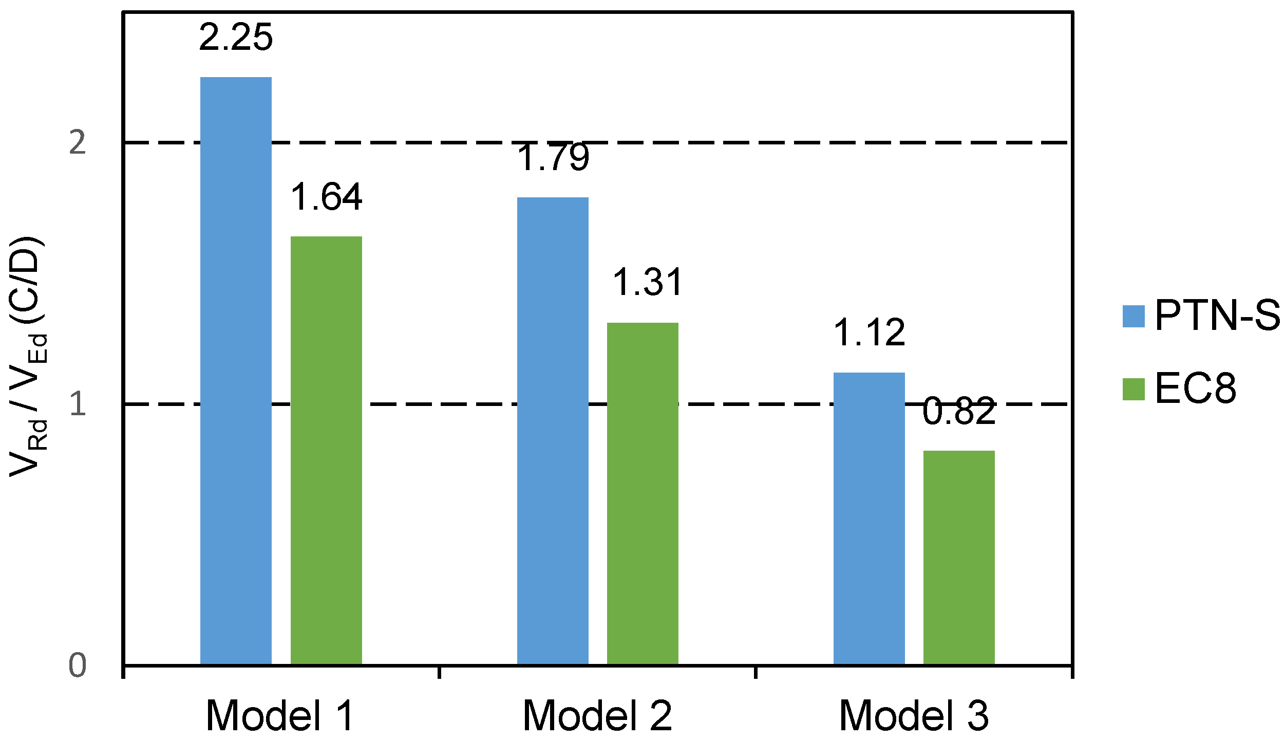
| Original 1 | Original 2 | Original 3 | ||||
|---|---|---|---|---|---|---|
| PTN-S | EC8 | PTN-S | EC8 | PTN-S | EC8 | |
| (1) | (2) | (3) | (4) | (5) | (6) | |
| C: Shear Capacity | 2088.35 | 3480.58 | 1670.68 | 2784.46 | 1044.18 | 1740.29 |
| D: Design Shear Force | 930.59 | 2127.16 | 930.59 | 2127.16 | 930.59 | 2127.16 |
| 2.25 | 1.64 | 1.79 | 1.31 | 1.12 | 0.82 | |
| Retrofitted 1 | Retrofitted 2 | Retrofitted 3 | ||||
|---|---|---|---|---|---|---|
| PTN-S | EC8 | PTN-S | EC8 | PTN-S | EC8 | |
| (1) | (2) | (3) | (4) | (5) | (6) | |
| C: Shear Capacity | 2506.02 | 4176.69 | 2001.04 | 3341.36 | 1253.01 | 2088.34 |
| D: Design Shear Force | 969.88 | 2216.97 | 969.88 | 2216.97 | 969.88 | 2216.97 |
| 2.58 | 1.88 | 2.06 | 1.51 | 1.29 | 0.94 | |
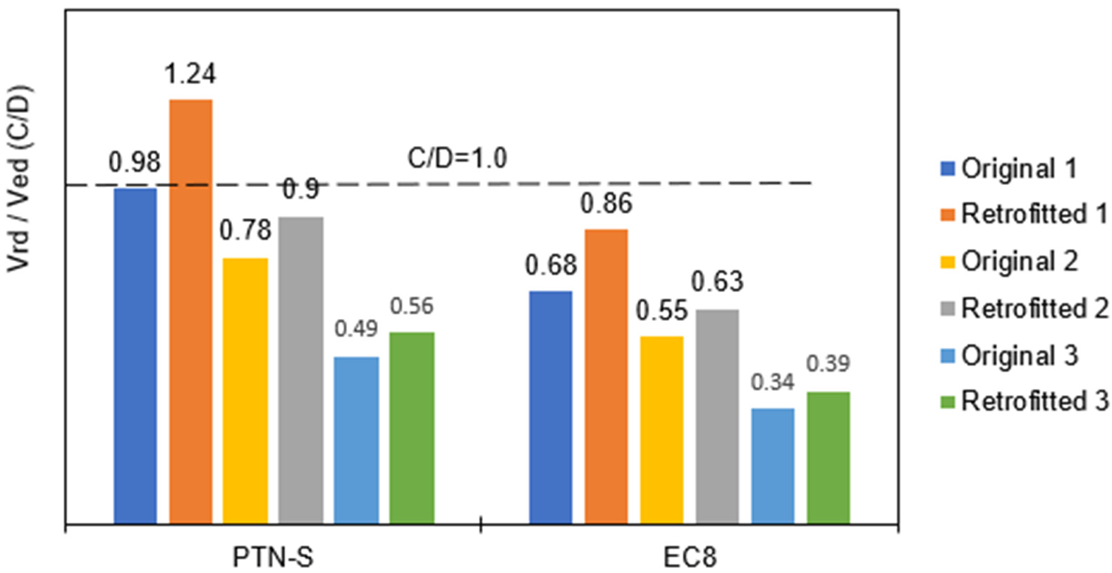
| Original 1 | Original 2 | Original 3 | ||||
|---|---|---|---|---|---|---|
| PTN-S | EC8 | PTN-S | EC8 | PTN-S | EC8 | |
| (1) | (2) | (3) | (4) | (5) | (6) | |
| C: Shear Capacity | 177.00 | 295.00 | 141.6 | 236.00 | 88.50 | 147.50 |
| D: Design Shear Force | 181.00 | 431.00 | 181.00 | 431.00 | 181.00 | 431.00 |
| 0.98 | 0.68 | 0.78 | 0.55 | 0.49 | 0.34 | |
| Retrofitted 1 | Retrofitted 2 | Retrofitted 3 | ||||
|---|---|---|---|---|---|---|
| PTN-S | EC8 | PTN-S | EC8 | PTN-S | EC8 | |
| (1) | (2) | (3) | (4) | (5) | (6) | |
| C: Shear Capacity | 212.40 | 354.00 | 169.6 | 283.20 | 106.20 | 177.54 |
| D: Design Shear Force | 171.75 | 408.97 | 189.20 | 450.54 | 189.64 | 455.23 |
| 1.24 | 0.86 | 0.90 | 0.63 | 0.56 | 0.39 | |
| Original 1 | Original 2 | Original 3 | |||||
|---|---|---|---|---|---|---|---|
| Cantilever Model | EFM | Cantilever Model | EFM | Cantilever Model | EFM | ||
| PTN-S | Δe (mm) Δd (mm) d (%) | 3.590 5.385 (0.048) | 2.270 3.405 (0.030) | 4.240 6.36 (0.056) | 2.690 4.035 (0.036) | 6.010 9.015 (0.080) | 3.900 5.850 (0.052) |
| EC8 | Δe (mm) Δd (mm) d (%) | 13.94 20.91 (0.186) | 7.440 11.16 (0.099) | 16.440 24.66 (0.220) | 6.650 9.975 (0.089) | 23.17 34.755 (0.310) | 2.09 3.135 (0.138) |
| Retrofitted 1 | Retrofitted 2 | Retrofitted 3 | |||||
|---|---|---|---|---|---|---|---|
| Cantilever Model | EFM | Cantilever Model | EFM | Cantilever Model | EFM | ||
| PTN-S | Δe (mm) Δd (mm) d (%) | 3.540 8.850 (0.079) | 2.020 5.05 (0.045) | 4.190 10.475 (0.093) | 2.390 5.975 (0.053) | 5.930 14.825 (0.132) | 3.440 8.600 (0.076) |
| EC8 | Δe (mm) Δd (mm) d (%) | 8.330 20.825 (0.186) | 1.090 2.725 (0.024) | 9.840 24.600 (0.219) | 1.290 3.225 (0.029) | 9.268 34.675 (0.309) | 1.050 4.625 (0.041) |
Disclaimer/Publisher’s Note: The statements, opinions and data contained in all publications are solely those of the individual author(s) and contributor(s) and not of MDPI and/or the editor(s). MDPI and/or the editor(s) disclaim responsibility for any injury to people or property resulting from any ideas, methods, instructions or products referred to in the content. |
© 2023 by the authors. Licensee MDPI, Basel, Switzerland. This article is an open access article distributed under the terms and conditions of the Creative Commons Attribution (CC BY) license (https://creativecommons.org/licenses/by/4.0/).
Share and Cite
Blagojević, P.; Brzev, S.; Cvetković, R. Seismic Retrofitting of Mid-Rise Unreinforced Masonry Residential Buildings after the 2010 Kraljevo, Serbia Earthquake: A Case Study. Buildings 2023, 13, 597. https://doi.org/10.3390/buildings13030597
Blagojević P, Brzev S, Cvetković R. Seismic Retrofitting of Mid-Rise Unreinforced Masonry Residential Buildings after the 2010 Kraljevo, Serbia Earthquake: A Case Study. Buildings. 2023; 13(3):597. https://doi.org/10.3390/buildings13030597
Chicago/Turabian StyleBlagojević, Predrag, Svetlana Brzev, and Radovan Cvetković. 2023. "Seismic Retrofitting of Mid-Rise Unreinforced Masonry Residential Buildings after the 2010 Kraljevo, Serbia Earthquake: A Case Study" Buildings 13, no. 3: 597. https://doi.org/10.3390/buildings13030597