Article

Novel Energy Management Scheme for a Permanent Magnet Electric Drive-Based Hybrid Vehicle Using Model Predictive Control

1
School of Electrical Engineering, Pontificia Universidad Católica de Valparaíso, Valparaiso 2340000, Chile
2
Electronics Engineering Department, Universidad de las Americas-Puebla, Sta. Catarina Martir, Cholula 72820, Puebla, Mexico
*
Author to whom correspondence should be addressed.
Machines 2024, 12(1), 3; https://doi.org/10.3390/machines12010003 (registering DOI)
Submission received: 9 November 2023 / Revised: 7 December 2023 / Accepted: 15 December 2023 / Published: 20 December 2023
(This article belongs to the Special Issue Electrical Machines in Electric Vehicles)

Abstract

:
The present work deals with the design of a traction system for a hybrid vehicle using a PMSM-type motor, including an energy regeneration stage, using a Neutral Point Piloted (NPP) inverter. Optimal operation allows the motor to be supplied in the traction stage with the correct energy in such a way that it operates properly; on the other hand, during braking, it facilitates the transfer of energy in regenerative mode to the DC bus, storing the greatest amount of energy in the storage elements, which, in this case, refers to a battery bank. It also includes a DC-DC bidirectional boost interleaved converter to regulate the DC voltage levels both in traction and in braking. Its fundamental characteristic is that with a reduced number of switching devices, it allows for the reduction in DC voltage of the DC bus with adequate characteristics, constant and stable, regardless of abrupt changes in the output voltage reference value. Also, other features include oscillation control, that is, reducing or increasing oscillations according to operating conditions. Its transient operation is excellent, since the settling time is considerably reduced, which implies that the voltage of the DC bus does not cause mishaps in the operation of the motor. In its operation as a boost converter, in the event of any voltage value of the DC bus, the converter raises the voltage value according to the reference conditions. Similarly, control allows the voltage to be held at a stable value regardless of changes in the set point. This work presents a novel energy management scheme for permanent magnet electric drive based on a Model Predictive Control strategy, thus contributing to the effective energy management of a standard hybrid electric vehicle driving cycle. Results obtained using a real-time Hardware-in-the-Loop (HIL) platform showed the effectiveness of Model Predictive Control in dealing with power flow management while ensuring control of electric drive in all the required speed–torque profiles.

1. Introduction

The critical situation of the environment due to pollution from various sources, deforestation, gas emissions, combustion of fossil fuels, etc., has been mentioned on countless occasions. Due to this concern, for years, scientific research efforts have been oriented towards reversing the effects of the destruction of the planet and, in particular, ensuring that vehicles (air, land, sea) are ecologically friendly, that is, that at least their source of energy for propulsion does not dispose of polluting gases or other substances that contribute to the deterioration of the ecology of our environment and that the means to obtain fuel are not so invasive or destructive with respect to the environment. The process has not been easy, since although many solutions have emerged, they do not guarantee to reduce their polluting emissions or toxic waste to zero. Among them, electric vehicles have represented a response to this need, and so far, great progress has been made, but there are still aspects to be resolved; There are also other solutions, such as hybrid vehicles and other configurations, which combine electrical energy and the combustion of fossil fuels, trying to remedy the existing problematic that refers to autonomy. To contribute to advances in the field of hybrid vehicles, this paper proposes the design and implementation of a power train for a compact hybrid vehicle. This system controls a permanent magnet synchronous motor (PMSM), and its power stage consists of a battery bank as a storage element and a boost interleaved converter. The DC bus is made up of a capacitor bank to maintain the DC voltage that feeds the motor with good characteristics, as well as a Neutral Point Piloted (NPP)-type inverter to supply the energy required by the load, through the PMSM. The control algorithms used to control the converters are analyzed and evaluated in such a way that their operation is the most efficient, thus allowing for a reduction in the aging of batteries and prolonging the useful life of power semiconductor devices and other elements. In this way, it is expected to increase the autonomy of the vehicle. This aspect is confirmed by performing simulations and making comparisons with other similar ones. Specifically, the bidirectional DC-DC converter, along with systems for energy storage, has become a promising option for many energy-related systems, including hybrid vehicles [1], fuel cell vehicles, fuel, renewable energy systems, etc. It not only reduces cost and improves efficiency but also improves system performance. In electric vehicle applications, an auxiliary energy storage battery absorbs the regenerated energy that is fed back to the electric machine. In addition, a bidirectional DC-DC converter is also required to process the power stored in the battery arrangement to drive the high-voltage bus during vehicle starting, acceleration, and hill-climbing operations [1]. Bidirectional DC-DC converters are increasingly being used to achieve power transfer between two DC power sources due to their ability to reverse the direction of current flow and thus power in either direction. Multiple-input bidirectional DC-DC converters can be used to combine different types of power sources [1,2,3,4,5,6,7,8]. In this context, an efficient energy management and control scheme is required to deal with both the energy flow problem and electric drive, consisting of PMSM control. In this field of application, several control techniques for PMSMs appear suitable for HEV applications [9,10,11]. Model Predictive Control (MPC) has attracted significant attention in research due to its rapid dynamics, adaptability, and convenient integration of nonlinear elements and constraints while incorporating additional control needs into the same control framework [12,13,14,15]. This work presents a novel energy management scheme for permanent magnet electric drive based on a Model Predictive Control strategy, thus contributing to the effective energy management of a standard hybrid electric vehicle driving cycle.

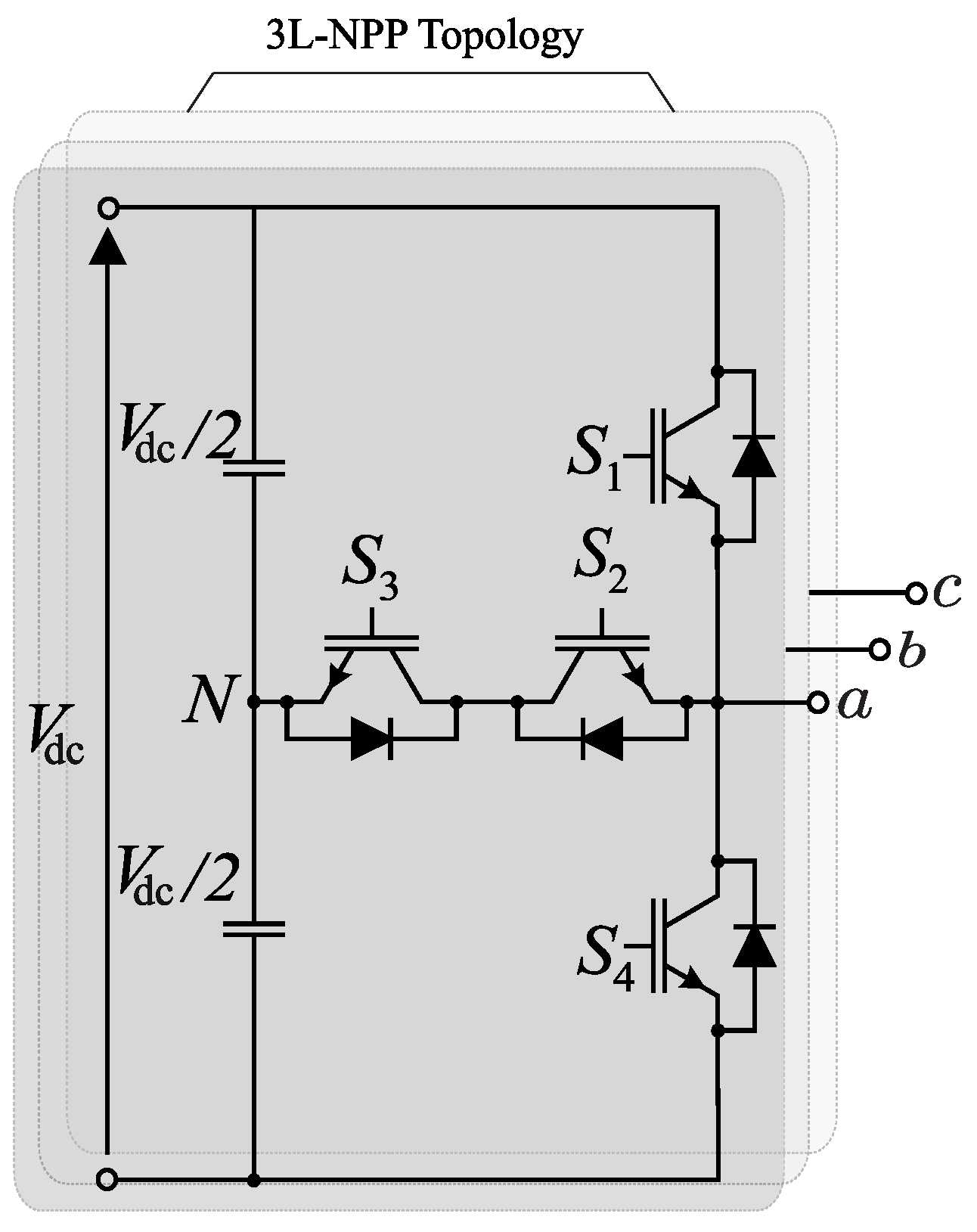
1.1. Inverter Topology

An NPP inverter is used for the inverter side. The power converter topology is shown in Figure 1. The NPP inverter consists of four controlled switches (IGBTs in this case) and four anti-parallel diodes for each leg.
The converter basic cell is capable of synthesizing three output voltage levels, depending on the switching states, which are summarized in Table 1. Considering the three-phase output voltages, the NPC converter has 27 voltage vectors. The corresponding space vector diagram is represented in Figure 2. Small redundancy vectors are used for the DC-Link balance in the control scheme.
Switching state P indicates that upper switches S 1 and S 2 are turned on in their respective phase. State O implies that switches S 2 and S 3 are turned on, and state N implies that the lower switches, S 3 and S 4 , are turned on, as shown in Table 1. In other words, state [ P , N , N ] means [ V d c / 2 , 0 , 0 ] in the ABC phase, respectively.

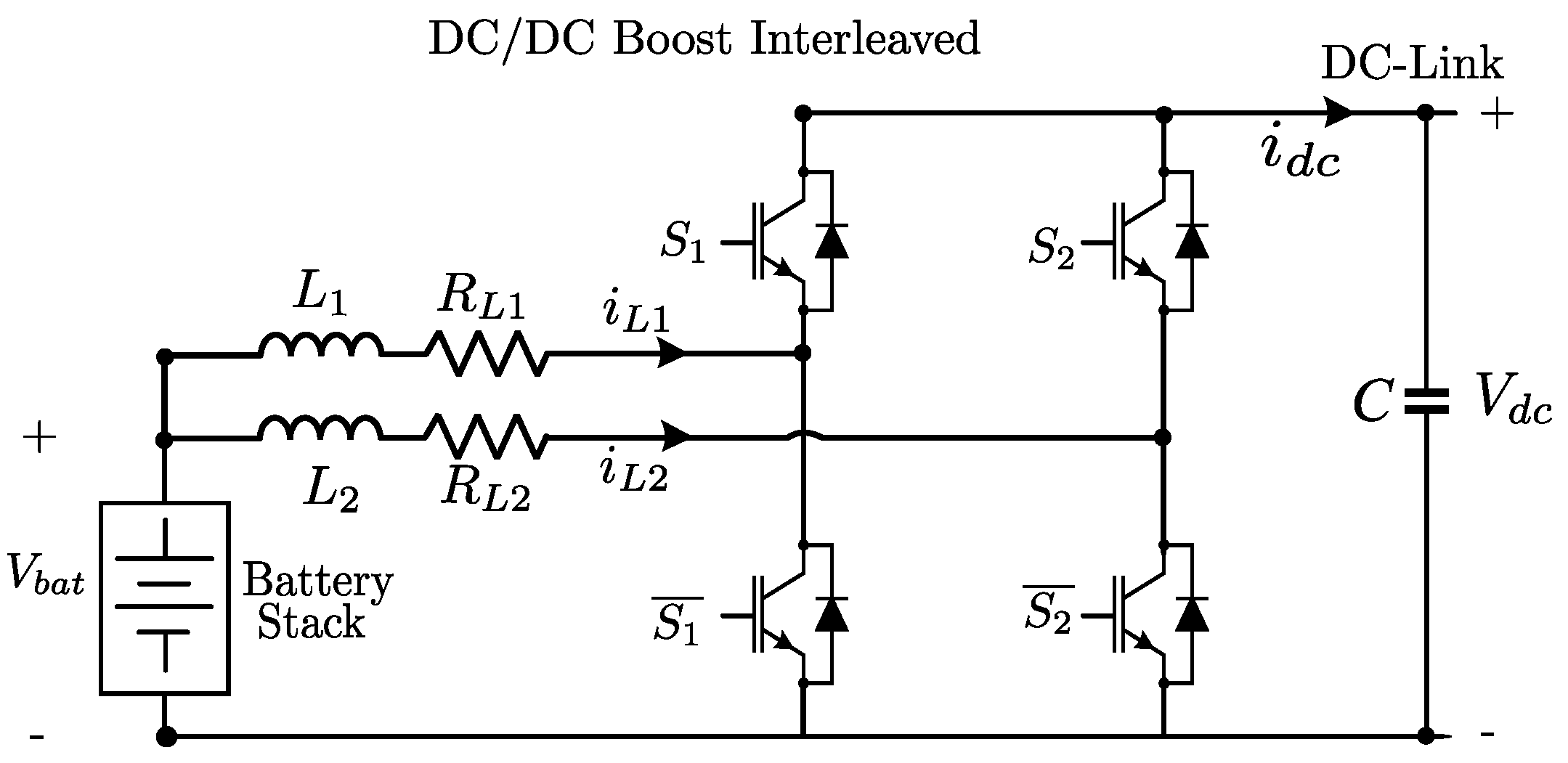
1.2. Bidirectional DC-DC Converter

Bidirectional converters can transfer energy in both directions, that is, both input and output and vice versa, by changing the current flow direction. Most of the existing bidirectional DC-DC converters fall into the generic circuit topology, which can be characterized by a current or voltage source, switched energy storage elements, and switching devices [16,17,18,19,20].
For this application, a non-insulated DC-DC interleaved converter is chosen because of its simple topology with a reduced number of components and control scheme, while taking advantage of an increased duty cycle towards unity. The topology is shown in Figure 3. The mathematical model restricted by switching states S 1 and S 2 is described by Equations (1) and (2).
V b a t = R L i L ( 1 , 2 ) + L d d t i L ( 1 , 2 ) + V d c ( 1 S ( 1 , 2 ) )
i L ( 1 , 2 ) ( 1 S ( 1 , 2 ) ) = C d d t V d c + i d c
In the above, the sub-index ( 1 , 2 ) corresponds to the respective interleaved branch, and S corresponds to the switch signal, e.g., i L 1 corresponds to the upper interleaved branch current. It has to be noted that this model corresponds to a nonlinear model, so the use of a nonlinear control strategy, that is, Model Predictive Control (MPC), is considered for this application to take advantage of the nonlinearities in control scheme performance.

1.3. Permanent Magnet Synchronous Machine Mathematical Model
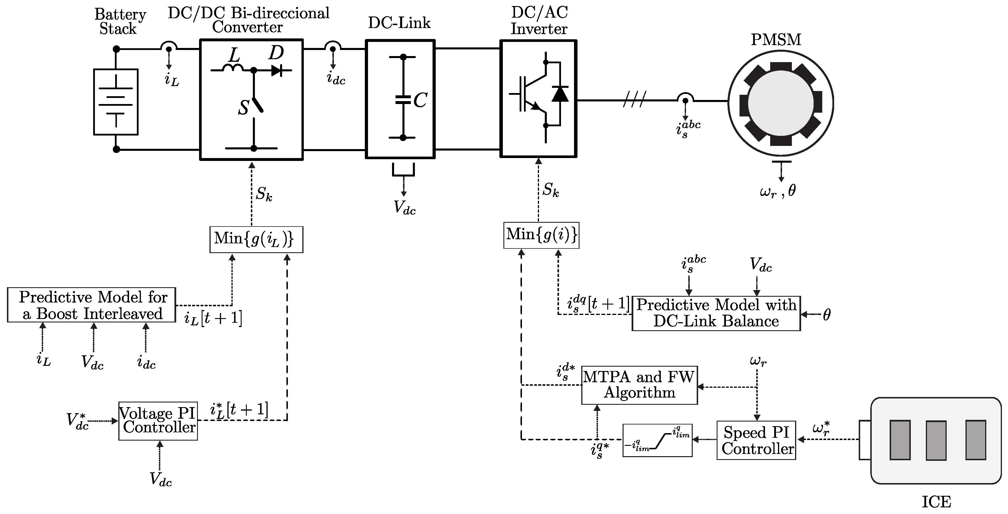
The machine to be controlled is a Permanent Magnet Synchronous Motor (PMSM) with salient poles. The stator equation is represented in the stationary α β reference frame, as shown in Equation (3).
V s α β = R s i s α β + d d t ψ s α β
where V s , R s , i s , and ψ s represent the stator voltage, stator resistance, stator currents, and flux linkage of the motor, respectively. The flux linkage of the motor is dependent on the stator current and the magnetizing inductance ( L m ).
ψ s α β = L s i s α β + ψ M e j θ k
Note that the flux linkage of the motor depends on the rotation angle, making it more challenging to develop a dynamic model in a stationary reference frame. However, by using a reference frame that rotates by an angle θ k , as represented in Equation (5), it becomes possible to define a dynamic model.
d q 0 = c o s θ k s i n θ k 0 s i n θ k c o s θ k 0 0 0 1 α β γ
With field orientation, it is possible to obtain the stator equations in a synchronous reference frame (dq frame).
V s d = R s i s d + L d d d t i s d p ω r L q i s q
V s q = R s i s q + L q d d t i s q + p ω r L d i s d + p ω r ψ M
where L d and L q are the direct-axis inductance and quadrature-axis inductance, respectively; ψ M represents the flux linkage produced by the permanent magnets; ω r denotes the rotor speed; and p represents the number of pole pairs.
On the other hand, the electrical torque is represented as
T d q = 3 2 p [ ψ M i s q + i s q i s d ( L d L q ) ]
Note that in a salient pole machine, the inductance values satisfy the condition L d < L q , which means that the last term in the stator equations generates torque known as reluctance torque. This is an advantage in drive control, as it allows for the implementation of Maximum Torque Per Ampere (MTPA) control strategies.

2. Control Scheme

In this section, the control schemes used will be detailed according to the system shown in Figure 4.

2.1. Model Predictive Control of the DC/DC Interleaved Converter

The main objective of the DC/DC converter is to maintain a constant DC-Link with the power provided by the battery. That is why the predictive control model is defined based on the converter’s output voltage [21,22]. Predictive control has the peculiarity of being nonlinear control and consists in the approximation of predicting a specific variable using Euler discretization [23].
d x ( t ) d t x [ t + 1 ] x [ t ] T s
The time sampling period, T s , determines the performance of the prediction. A smaller T s results in better prediction accuracy, but it requires more computing time for the equipment. Therefore, it is essential to define an optimal sampling time that balances prediction accuracy and computational efficiency.

2.1.1. Converter Prediction Model

By applying Euler discretization to the dynamic model described by Equations (1) and (2), we obtain
i L ( 1 , 2 ) [ t + 1 ] = i L ( 1 , 2 ) [ t ] 1 T s R L L T s L ( V b a t V d c ( 1 S ( 1 , 2 ) [ t ] ) )
V d c [ t + 1 ] = V d c [ t ] + T s C ( i L ( 1 , 2 ) [ t ] ( 1 S ( 1 , 2 ) [ t ] ) i d c )
where the sub-index ( 1 , 2 ) represents each converter. In other words, there are two current predictions ( i L 1 [ t + 1 ] and i L 2 [ t + 1 ] ) and one voltage prediction but using two different models. Also, S [ k ] represents the states in which the switch can operate, i.e., {0,1}; depending on the switch state, there is a prediction.
It is possible to control the current and/or voltage through their predictions. Voltage can be directly controlled using its prediction and a subsequent cost function [24], but the main issue lies in the lack of control over the input current ( i L ), which can become unstable. For this reason, cascaded current control is implemented.

2.1.2. Input Current Control

There are different ways to ensure a constant output voltage using input current control. One approach involves neglecting the losses of the DC/DC converter and defining the input power as equal to the DC-Link power, i.e., P i n P d c , where a reference current can be defined as i r e f = P i n / V i n and P i n depends on V d c r e f . Although this is a control method, it does not guarantee an optimal voltage response [24,25]. Therefore, in this work, an external voltage loop control, V d c , is employed, controlled by a PI controller, and an internal current loop is controlled using MPC.
To design the PI controller, the transfer function between the input current ( i L ) and the output voltage ( V d c ) is defined [26]:
G h ( s ) = V d c i L D R 2 1 s L D 2 R 1 + s R C 2
where D = 1 D , where D corresponds to the steady-state duty cycle. Furthermore, L , R , C are parameters of the boost interleaved converter. The control action of the voltage PI controller determines the reference current ( i r e f ), which enters in the cost function alongside the predicted current defined in Equation (10).

2.1.3. Current Cost Function

Since the converter is interleaved, each input current has its own prediction, so the reference current is divided between them, resulting in the following form:
g 1 ( i ) = i r e f 2 i L 1 [ t + 1 ]
g 2 ( i ) = i r e f 2 i L 2 [ t + 1 ]
where i L 1 and i L 2 correspond to the currents of each boost interleaved converter, respectively. Therefore, the state of the switch for each converter that produces a lower cost function is chosen using control.

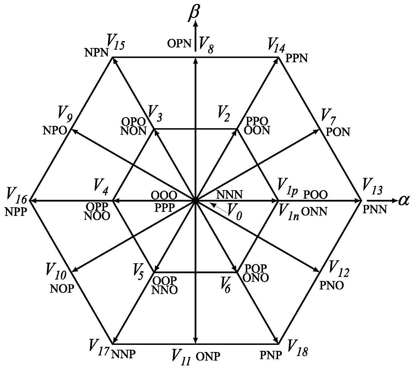
2.2. Model Predictive Control of the Inverter

Inverter control consists of two control loops: external speed control with a PI controller and MTPA (Maximum Torque Per Ampere) and internal current control with MPC.
To control the electrical drive and maintain DC-Link balance, an MPC strategy is proposed using the voltage space vectors shown in Figure 2. Redundant vectors are utilized for DC balance.

2.2.1. Current Prediction Model

By applying the Euler method to Equations (6) and (7), the current predictions are obtained:
i s d [ t + 1 ] = ( 1 T s R s L d ) i s d [ t ] + T s p ω r L q L d i s q [ t ] + T s L d V s d [ t ]
i s q [ t + 1 ] = ( 1 T s R s L q ) i s q [ t ] T s p ω r L d L q i s d [ t ] + T s L q V s q [ t ] T s p ω r ψ M L q
The accuracy of the current predictive model relies on the accurate estimation of machine parameters. The poor estimation of these parameters can lead to suboptimal control performance. In this case, the 27 voltage vectors of the NPC ( v s ) are used as inputs for the current model, resulting in 27 different predictions. These predictions are then evaluated based on a functional cost assessment.

2.2.2. DC-Link Voltage Prediction Model

To achieve DC-Link balance, a prediction of each capacitor voltage is used. The capacitance values of both capacitors are assumed to be equal ( C 1 = C 2 ). By applying the Law of Kirchhoff’s Current (LKC) at the neutral clamped node, expressions for the capacitor voltages can be derived [27].
d d t V c 1 = 1 2 C i o
d d t V c 2 = 1 2 C i o
where i o is the neutral current that flows through S 2 and S 3 in Figure 1. This current depends on the voltage vector.
i o ( i ) = i S i i o
For instance, if the second vector voltage, V 2 p , is selected from the space vector voltages in Figure 2, the state of the output voltage can be represented as {O, N, N}. This configuration indicates that there is zero voltage in phase A and V d c / 2 in phases B and C. In this case, the neutral current, i o , is equal to i a , as phase A is connected to the neutral clamped node.
By applying the Euler method for discretization, we obtain the prediction voltage for the DC-Link.
V c 1 [ t + 1 ] = V c 1 [ t ] + 1 2 C i o [ t ] T s
V c 2 [ t + 1 ] = V c 2 [ t ] 1 2 C i o [ t ] T s

2.2.3. Cost Function

At each sampling time, the MPC algorithm predicts the state variables to be controlled and then calculates the sequence of control actions that minimize the cost over the desired horizon by solving a constrained optimization problem, as described by Equation (22). The controller then applies the control action, which satisfies the optimization problem.
g ( i ) = i s * d i s d [ t + 1 ] 2 + i s * q i s q [ t + 1 ] 2 + λ V c 1 [ t + 1 ] V c 2 [ t + 1 ] 2
where λ corresponds to the weighting factor that prioritizes DC voltage control.

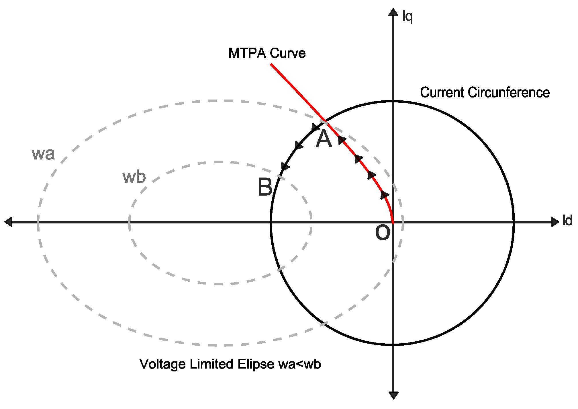
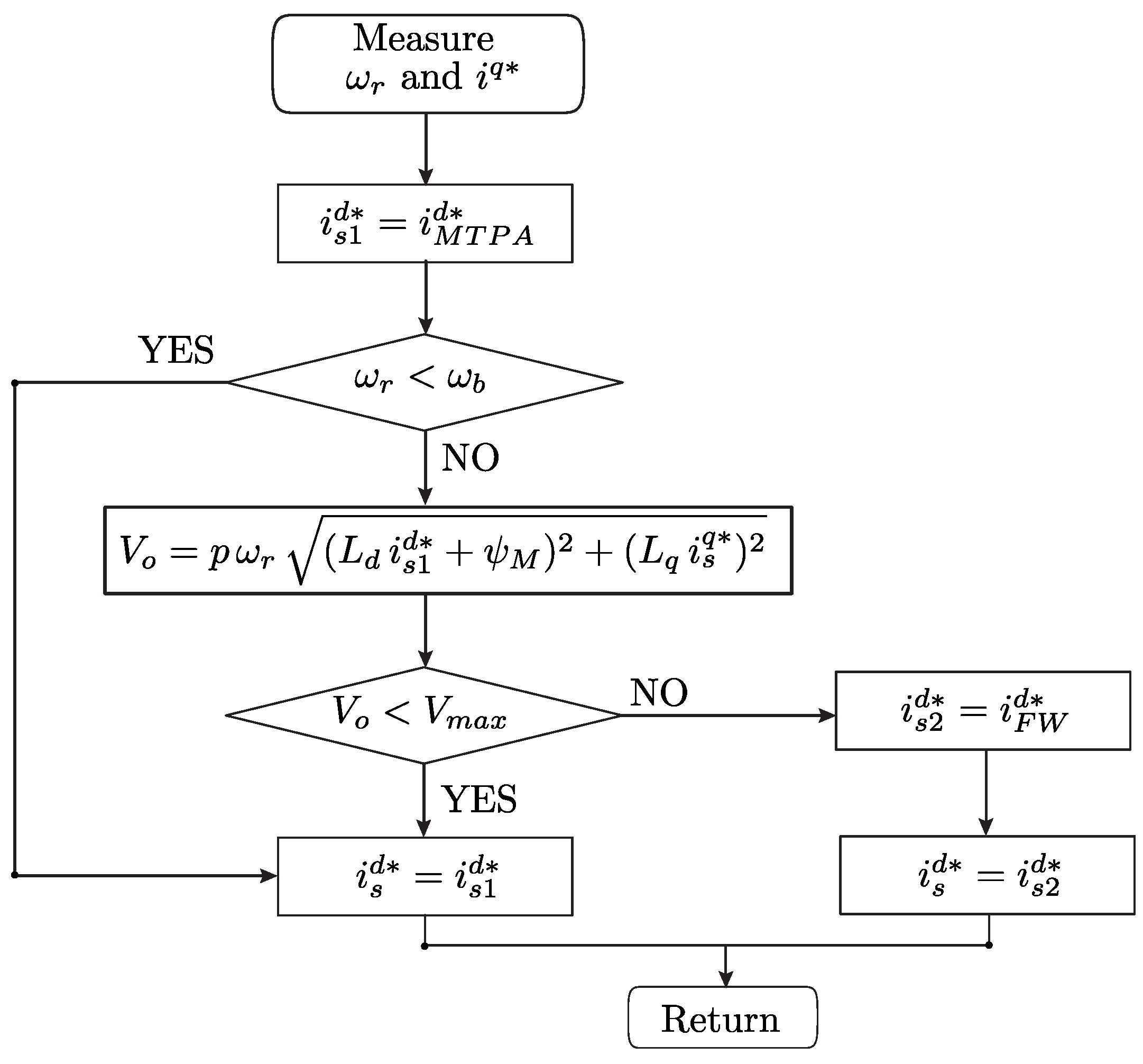
2.2.4. Speed Control and MTPA Technique

Speed control is based on mechanical dynamics, as described by Equation (23).
H ω ( s ) = 1 J s + B m
where J corresponds to the moment of inertia, and B m , to the motor friction coefficient.
There are two main approaches for speed control: Zero Direct Current (ZDC) and Maximum Torque Per Ampere (MTPA). Although the ZDC strategy is an effective method, MTPA can take advantage of the reluctance torque of the machine without entering into the saturation region, thus reducing the required currents for a given torque requirement.
MPTA control does not set the current on the direct axis to zero but gives it a value to maximize the torque. While this technique is useful, it is not sufficient for high-speed drive, as control performance tends to decrease significantly. For this reason, a field-weakening strategy is also implemented to set the current on the direct axis in such a way as to take advantage of the available torque.
Equations (24) and (25) represent the current and voltage limiting functions, respectively.
I s = ( i s d ) 2 + ( i s q ) 2 I s , m a x
V s = ( V s d ) 2 + ( V s q ) 2 V m a x
By taking into account the voltage limitation and the dynamic model described in Equations (6) and (7), it is possible to derive an expression for the currents in the synchronous reference frame (dq) as a function of the synchronous speed, machine inductance, and stator voltage. It is important to note that the stator resistance, R s , is neglected, as R s 0 .
i s d + ψ M L d 2 V s , m a x ω e L d 2 + i s q 2 V s , m a x ω e L q 2 = 1
The locus of (26) and (24) is shown in Figure 5.
The intersection of Equation (26)’s ellipse and the current circumference defines the operating zone of the motor. It should be noted that the motor operates in the second quadrant, with positive i s q and negative i s d .
The Maximum Torque Per Ampere (MTPA) curve represents the operating point at which there is minimum current for maximum torque. In other words, this curve represents the optimal balance between current and torque. Trajectory OA in Figure 5 corresponds to this operation. If the speed continues to increase, the current is limited by the circumference, so point AB operates in the field-weakening zone. The limiting speed that represents one zone or the other is called base speed ( ω b ) and is defined as
ω b = 4 T m a x R s 3 p + 4 T m a x R s 3 p 2 4 ψ M 2 ( R s I s , m a x 2 V m a x 2 ) 2 ψ M 2
where R s , ψ , p correspond to the parameters of the machine and V m a x corresponds to the maximum voltage that the inverter can deliver. The maximum torque of the machine can be calculated as follows:
T m a x = 3 p 2 ψ M I s . m a x
When the motor speed operates below this base speed, it operates in the MTPA zone, which defines a current on the direct axis in the following form:
i M T P A d * = ψ M 2 ( L q L d ) ψ M 2 4 ( L q L d ) 2 + ( i q * ) 2
On the other hand, if it operates above the base speed, the electric drive works in the field-weakening zone, and the direct current is represented as
i s , F W d * = ψ M L d + 1 L d V m a x 2 ω e 2 + ( L q i s q * ) 2
Under this condition, there is a small torque margin that can be exploited based on the voltage delivered by the inverter, as described by Equation (31).
V o = p ω r ( L d i M T P A d * + ψ M ) 2 + ( L q i s q * ) 2
where V o is the voltage induced by the machine. When V o equals the voltage to which it is connected, it is not possible to generate current and thus torque. However, if operating with lower torque, it is possible to continue increasing the speed as long as this voltage expression is lower than the machine’s voltage. This implies an operating margin within the MTPA zone.
Finally, current i s d , obtained from the algorithm, limits current i s q according to the following expression:
i l i m q = I s , m a x 2 ( i s d * ) 2
In Figure 6, the MTPA and field-weakening algorithm is detailed. Current i s d is defined depending on whether the operation is in the MTPA or FW zone, based on the machine’s base speed and the maximum voltage that the inverter can deliver. The current references obtained with this process are fed to the predictive control algorithm.
In Figure 4, the complete scheme is shown, considering predictive control for the DC/DC stage and the NPP inverter stage, with an MTPA scheme and balance in the DC-link based on voltage vectors for the defined topology.

2.3. Convergence of the MPC Algorithm

MPC optimization approximates an infinite-time problem by solving over a discrete, finite horizon (N). Let us extend the optimization problem defined in Equation (41) as given in Equation (33):
min J ( x ( k ) , u ( k ) ) = l = 0 N d ( z ( k + l | k ) , T ( l ) )
The optimization problem is subjected to the discrete state-space description of the dynamic system given in Equation (34).
x ( k + l + 1 | k ) = A x ( k + l | k ) + B u ( k + l | k ) y ( k + l | k ) = C x ( k + l | k ) + D u ( k + l | k ) z ( k + l | k ) = E x ( k + l | k ) + F u ( k + l | k )
where z ( k ) corresponds to the tracking output that converges to a bounded target set T as k N , and d ( z ( k + l | k ) , T ( l ) ) , to the metric given by each element of the tracking output set z ( k + l ) to each target set element T ( l ) , as given in Equation (35).
d ( z ( k + l | k ) , T ( l ) ) = m i n | | z ( l ) T ( l ) | |
If the optimization problem min J ( x ( k ) , u ( k ) ) , k > 0 , has a feasible solution for state variable x ( k ) for any control action u ( k ) , the optimization problem is feasible and converges to the global optimum [28], and as a consequence, tracking output z ( k ) converges to target set T within finite set of samples N as k N [29]. Moreover, in [30], it is shown that constrained discrete-time nonlinear MPC results in the stability of general attractors that are robust to sufficiently small disturbances, which ensures the stability of the MPC formulation under parameter uncertainty.

3. Vehicle Dynamics

The load on the electrical machine in the system is determined by the dynamic characteristics of the vehicle. It is necessary to consider the fundamental components of the vehicle. Generally, there are three types of forces acting on a vehicle while it is in motion: aerodynamic drag ( F D ), rolling resistance ( F R ), and climbing resistance ( F C ) [31].
Aerodynamic drag corresponds to the resistance encountered by a vehicle as it moves through air. This force depends on factors such as air density, vehicle speed, and the vehicle’s frontal area. Rolling resistance is the cumulative effect of all friction forces between the tires and the road surface. This force is directly influenced by the mass of the vehicle. Climbing resistance comes into play when a vehicle travels on an inclined road, resulting in greater gravitational force compared with other scenarios.
Representing all these forces in equations is a complex task. To simplify the equations, a vehicle road-load force ( F v ) is introduced in [31] based on experimental testing. This force is defined as a function of three coefficients that represent the rolling resistance and aerodynamic drag. The expression for the road-load force is as follows:
F v = A + B v + C v 2
where v is the vehicle speed in m/sand the A, B, and C coefficients are defined with the EPA Coast-Down test. Normally, these coefficients represent the rolling resistance, the spinning rotational losses, and aerodynamic drag, respectively. On the other hand, the climbing force can be modeled as
F c = m g s i n θ
where m is the mass of the vehicle, g is the gravity acceleration, and θ is the angle of incline. Also, there is the acceleration force, F a = m a , which is defined as the acceleration or braking of the vehicle.
In order to start moving, the vehicle needs all these forces. According to Newton’s law, the motive force ( F m ) is given by
F m = F a + F v + F c
F m = A + B v + C v 2 + m g s i n θ + m d v d t
So, F m represent the force required to accelerate the vehicle. On the other hand, the torque of the vehicle can be defined as T m = F m r , where r is the wheel radius. Also, the moment of inertia of the vehicle is considered in the torque expression, defined as
T L = r A + B v + C v 2 + m g s i n θ + m d v d t + J v r d v d t
Finally, the gear ratio (g) of the mechanical system’s torque is defined as
T L = r g A + m g s i n θ + B v + C v 2 + m + J v r 2 d v d t
Finally, Expression (41) corresponds to the road-load torque in function of the speed of the vehicle. This torque is required by the electrical machine.

4. Results

Simulation and Hardware-in-the-Loop results of the proposed optimization strategy are presented in this section. The complete system analysis was performed using PLECS and then validated with the real-time platform RT-Box. The parameters used in the PLECS simulation and the subsequent Hardware-in-the-Loop (HIL) validation are defined in Table 2.
As previously mentioned, the HWFET driving cycle [32,33] was used to analyze the dynamic behavior of the control loops defined for the inverter and DC/DC converter. For a more thorough analysis, the most critical points where higher d v / d t occurs were selected. The velocity profile of the vehicle was applied in Equation (41) to obtain the motor torque. Figure 7 and Figure 8 show the velocity and torque profiles with which the machine operated. The speed represented in Figure 7 is the speed of the PMSM motor, but to obtain this characteristic, the velocity profile of the vehicle was taken and subjected to the respective transformations using the gear ratio and wheel ratio defined in Table 2. Further, we highlight points where the velocity exceeds the base velocity and the torque exhibits negative values. In the previous sections, features of the vehicle, such as rolling resistance and aerodynamic drag, were emphasized. Although these variables were not taken into account for the simulation, they are considered in the vehicle’s torque through the constants A, B, and C, as defined in Equation (36). In other words, these vehicle variables determine the characteristics of the motor torque, along with the vehicle’s speed.
The simulations were verified in real time using Plexim RT-Box 3 CE HIL, using a TI C2000 microcontroller, as shown in Figure 9. The output signals were captured with a LaunchPad Interface connected to an oscilloscope.
Initially, the DC/DC converter operated to set the DC-Link voltage to 400 (V) in order to properly operate the inverter, as shown in Figure 10.
In Figure 11, the currents on the synchronous d q -axis during the operation described are shown. It can be observed that current i s q is directly proportional to the torque applied to the motor. When the machine’s speed exceeds the base speed, the MTPA algorithm with field weakening allows for the continued control of the required torque, as evident in the current control ( i s q ) in Figure 11, which maintains the characteristic waveform of the required load torque. On the other hand, current i s d is not held at zero but is varied as needed by the MTPA algorithm. While the direct current does not exhibit a significant magnitude compared with the quadrature current, it does influence the machine’s operation. As the torque increases, current i s d also increases to compensate for the current level in conjunction with i s q . In the case of field weakening, the torque is not so high as to require a large direct current that weakens the machine’s magnets, so its phenomenon is noticeable but on a smaller scale.
Operating point ( 1 ) indicates the change in the direction of power flow as the torque becomes negative. The following images correspond to this particular point.
In Figure 12, it can be observed that the torque has initially a value of 20 (Nm) and undergoes a change to −56 (Nm), as defined in the torque characteristic in Equation (41). The yellow signal corresponds to the torque delivered by the vehicle’s speed characteristic, while the blue signal corresponds to the machine’s torque delivered by the proposed control algorithm.
Figure 13 shows the DC-Link voltage at the moment of a change in the direction of power flow. At this point, the predictive control balance scheme, as shown in Equations (20)–(22), is already in operation, so the voltages of each capacitor are balanced. At the moment of power change, there is a slight voltage overshoot, but it is easily recovered thanks to the voltage PI controller and the current prediction algorithm.
Figure 14 shows the change in power flow direction, thus changing the three-phase current ( i s a b c ) sequence, as well as the change in the polarity direction of direct current component i s q , as shown previously in Figure 11.
In Figure 15, the currents in each inductor in the interleaved DC/DC converter are shown. The control was designed in order to obtain symmetrical distributed currents among all inductors. Additionally, it can be seen that the current changes from 20 (A) to −48 (A), with a small undershoot during the transition due to the inherent dynamics of the inductor. This results in a battery charge cycle due to the bidirectional nature of the DC/DC converter. In other words, when the motor operates with reverse torque, it charges the vehicle’s battery.

5. Conclusions

A control algorithm was defined under the operation of an electric vehicle to establish optimal battery operation and reduce electrical consumption under normal operating conditions. The proposed predictive control method offers versatility and significant capability in critical operations, such as high speeds or speed changes that result in variations in power flow. Furthermore, optimization challenges within the process were addressed, for instance, by achieving a DC-Link balance scheme through the prediction of capacitor voltages with T-Type converter voltage vectors. On the other hand, the boost interleaved converter allows for the stabilization of DC voltage for safe operation of the inverter stage. It also provides bidirectionality in power flow and enhanced power-handling robustness due to the use of two inductors.
Regarding the performance of the control method itself, it presents several advantages. One of these is the use of the Maximum Torque Per Ampere (MTPA) strategy. Using this technique, the electric motor is able to deliver higher power when the vehicle speed exceeds the base speed of the machine, thus increasing the operating range of the electric machine and allowing for fuel savings in the combustion engine.
Further, the NPP converter enables power flow and high output voltage quality, leading to more efficient energy utilization in the motor due to reduced harmonic content. However, it also introduces challenges, such as increased complexity in control due to its multiple voltage vectors and DC voltage balancing scheme.
The implementation of a predictive control model enables the possibility to achieve the balance of the DC-Link capacitors according to the required operational profile.
Finally, the boost interleaved converter also gives the ability to handle higher power levels; however, it also presents several complexity changes in its control strategy due to its nonlinearities, which was here solved using MPC.
A potential advantage of increased semiconductor usage is the reduction in thermal stress, as they handle less power. This opens up an opportunity for potential future research, such as the study of thermal stress for different converter topologies for HEV applications. In this field, it is well known that predictive control does not have a fixed switching frequency, thus increasing the impact on switching and conduction losses in power devices, conditioning their lifespan. As longevity is sought after in vehicles, the study of system performance in terms of semiconductor losses and thermal stress to define the lifespan could be a future research direction.
Another branch of research is the dependency of predictive control on system parameters. Several constructive parameters, such as resistance and leakage inductance, change due to temperature variations and magnetic saturation, conditioning the optimum trajectory for MPC. A future research direction could involve real-time parameter estimation to ensure optimum MPC operation.
Finally, the results were validated using a Hardware-in-the-Loop (HIL) platform with real-time simulations, yielding improved results comparable to those that would be obtained with an experimental setup. In summary, the predictive control scheme was proven to be a powerful and versatile approach capable of handling various control objectives, including DC balance, synchronous machine control, DC converter currents, and DC voltage regulation.

Author Contributions

Conceptualization, C.R., G.M.; methodology, M.P., C.R, C.S.; software, M.P., C.S., A.V.; validation, M.P.; formal analysis, C.R., G.M.; investigation, M.P., C.S. and A.V.; writing—original draft preparation, M.P. and C.S.; writing—review and editing, C.R. and M.P. All authors have read and agreed to the published version of the manuscript.

Funding

This research received no external funding.

Data Availability Statement

Data is contained within the article.

Conflicts of Interest

The authors declare no conflict of interest.

References

  1. Lai, J.S.; Nelson, D.J. Energy Management Power Converters in Hybrid Electric and Fuel Cell Vehicles. Proc. IEEE 2007, 95, 766–777. [Google Scholar] [CrossRef]
  2. Tao, H.; Kotsopoulos, A.; Duarte, J.; Hendrix, M. Multi-input bidirectional DC-DC converter combining DC-link and magnetic-coupling for fuel cell systems. In Proceedings of the Fourtieth IAS Annual Meeting. Conference Record of the 2005 Industry Applications Conference, 2005, Hong Kong, China,, 2–6 October 2005; Volume 3, pp. 2021–2028. [Google Scholar] [CrossRef]
  3. Tao, H.; Duarte, J.L.; Hendrix, M.A.M. High-Power Three-Port Three-Phase Bidirectional DC-DC Converter. In Proceedings of the 2007 IEEE Industry Applications Annual Meeting, New Orleans, LA, USA, 23–27 September 2007; pp. 2022–2029. [Google Scholar] [CrossRef]
  4. Chiu, H.J.; Huang, H.M.; Lin, L.W.; Tseng, M.H. A multiple-input DC/DC converter for renewable energy systems. In Proceedings of the 2005 IEEE International Conference on Industrial Technology, Hong Kong, China, 14–17 December 2005; pp. 1304–1308. [Google Scholar] [CrossRef]
  5. Su, G.J.; Cunningham, J.P.; Tang, L. A Reduced-Part, Triple-Voltage DC-DC Converter for Electric Vehicle Power Management. In Proceedings of the 2007 IEEE Power Electronics Specialists Conference, Orlando, FL, USA, 17–21 June 2007; pp. 1989–1994. [Google Scholar] [CrossRef]
  6. Mishima, T.; Hiraki, E.; Tanaka, T.; Nakaoka, M. A New Soft-Switched Bidirectional DC-DC Converter Topology for Automotive High Voltage DC Bus Architectures. In Proceedings of the 2006 IEEE Vehicle Power and Propulsion Conference, Windsor, UK, 6–8 September 2006; pp. 1–6. [Google Scholar] [CrossRef]
  7. Matsuo, H.; Lin, W.; Kurokawa, F.; Shigemizu, T.; Watanabe, N. Characteristics of the multiple-input DC-DC converter. IEEE Trans. Ind. Electron. 2004, 51, 625–631. [Google Scholar] [CrossRef]
  8. Hu, Y.; Tatler, J.; Chen, Z. A bidirectional DC/DC power electronic converter for an energy storage device in an autonomous power system. In Proceedings of the 4th International Power Electronics and Motion Control Conference, 2004. IPEMC 2004, Xi’an, China, 14–16 August 2004; Volume 1, pp. 171–176. [Google Scholar]
  9. Zhang, Z.; Liu, X. An Improved Super-Twisting Sliding Mode Single-Loop Control with Current-Constraint for PMSM Based on Two-Time Scale Disturbance Observer. IEEE Trans. Transp. Electrif. 2023, 1. [Google Scholar] [CrossRef]
  10. Zhang, J.; Ren, W.; Sun, X.M. Current-Constrained Adaptive Robust Control for Uncertain PMSM Drive Systems: Theory and Experimentation. IEEE Trans. Transp. Electrif. 2023, 9, 4158–4169. [Google Scholar] [CrossRef]
  11. Li, X.; Xie, M.; Ji, M.; Yang, J.; Wu, X.; Shen, G. Restraint of Common-Mode Voltage for PMSM-Inverter Systems with Current Ripple Constraint Based on Voltage-Vector MPC. IEEE J. Emerg. Sel. Top. Ind. Electron. 2023, 4, 688–697. [Google Scholar] [CrossRef]
  12. Kouro, S.; Perez, M.A.; Rodriguez, J.; Llor, A.M.; Young, H.A. Model Predictive Control: MPC’s Role in the Evolution of Power Electronics. IEEE Ind. Electron. Mag. 2015, 9, 8–21. [Google Scholar] [CrossRef]
  13. Dai, S.; Wang, J.; Sun, Z.; Chong, E. Transient Performance Improvement of Deadbeat Predictive Current Control of High-Speed Surface-Mounted PMSM Drives by Online Inductance Identification. IEEE Trans. Ind. Electron. 2022, 69, 12358–12368. [Google Scholar] [CrossRef]
  14. Rodriguez, J.; Garcia, C.; Mora, A.; Flores-Bahamonde, F.; Acuna, P.; Novak, M.; Zhang, Y.; Tarisciotti, L.; Davari, S.A.; Zhang, Z.; et al. Latest Advances of Model Predictive Control in Electrical Drives—Part I: Basic Concepts and Advanced Strategies. IEEE Trans. Power Electron. 2022, 37, 3927–3942. [Google Scholar] [CrossRef]
  15. Rodriguez, J.; Garcia, C.; Mora, A.; Davari, S.A.; Rodas, J.; Valencia, D.F.; Elmorshedy, M.; Wang, F.; Zuo, K.; Tarisciotti, L.; et al. Latest Advances of Model Predictive Control in Electrical Drives—Part II: Applications and Benchmarking with Classical Control Methods. IEEE Trans. Power Electron. 2022, 37, 5047–5061. [Google Scholar] [CrossRef]
  16. Matsuo, H.; Kurokawa, F. New Solar Cell Power Supply System Using a Boost Type Bidirectinal DC-DC Converter. IEEE Trans. Ind. Electron. 1984, IE-31, 51–55. [Google Scholar] [CrossRef]
  17. Chiu, H.J.; Lin, L.W. A bidirectional DC–DC converter for fuel cell electric vehicle driving system. IEEE Trans. Power Electron. 2006, 21, 950–958. [Google Scholar] [CrossRef]
  18. Chen, G.; Xu, D.; Wang, Y.; Lee, Y.S. A new family of soft-switching phase-shift bidirectional DC-DC converters. In Proceedings of the 2001 IEEE 32nd Annual Power Electronics Specialists Conference (IEEE Cat. No.01CH37230), Vancouver, BC, Canada, 17–21 June 2001; Volume 2, pp. 859–865. [Google Scholar] [CrossRef]
  19. Chen, G.; Xu, D.; Lee, Y.S. A family of soft-switching phase-shift bidirectional DC-DC converters: Synthesis, analysis, and experiment. In Proceedings of the Power Conversion Conference-Osaka 2002 (Cat. No.02TH8579), Osaka, Japan, 2–5 April 2002; Volume 1, pp. 122–127. [Google Scholar] [CrossRef]
  20. Fan, H.; Xu, D. A family of PWM plus phase-shift bidirectional DC-DC converters. In Proceedings of the 2004 IEEE 35th Annual Power Electronics Specialists Conference (IEEE Cat. No.04CH37551), Aachen, Germany, 20–25 June 2004; Volume 2, pp. 1668–1674. [Google Scholar] [CrossRef]
  21. Karamanakos, P.; Papafotiou, G.; Manias, S.N. Model predictive control of the interleaved DC-DC boost converter. In Proceedings of the 15th International Conference on System Theory, Control and Computing, Sinaia, Romania, 14–16 October 2011; pp. 1–6. [Google Scholar]
  22. Cheng, L.; Acuna, P.; Aguilera, R.P.; Ciobotaru, M.; Jiang, J. Model predictive control for DC-DC boost converters with constant switching frequency. In Proceedings of the 2016 IEEE 2nd Annual Southern Power Electronics Conference (SPEC), Auckland, New Zealand, 5–8 December 2016; pp. 1–6. [Google Scholar] [CrossRef]
  23. Karamanakos, P.; Liegmann, E.; Geyer, T.; Kennel, R. Model Predictive Control of Power Electronic Systems: Methods, Results, and Challenges. IEEE Open J. Ind. Appl. 2020, 1, 95–114. [Google Scholar] [CrossRef]
  24. Villarroel, F.A.; Espinoza, J.R.; Pérez, M.A.; Ramírez, R.O.; Baier, C.R.; Sbárbaro, D.; Silva, J.J.; Reyes, M.A. Stable Shortest Horizon FCS-MPC Output Voltage Control in Non-Minimum Phase Boost-Type Converters Based on Input-State Linearization. IEEE Trans. Energy Convers. 2021, 36, 1378–1391. [Google Scholar] [CrossRef]
  25. Villarroel, F.; Espinoza, J.; Pérez, M.; Sbárbaro, D.; Ramírez, R.; Baier, C. A new discretization method of model equations for predictive power converter control applications based on input-state linearization. In Proceedings of the IECON 2022—48th Annual Conference of the IEEE Industrial Electronics Society, Brussels, Belgium, 17–20 October 2022; pp. 1–5. [Google Scholar] [CrossRef]
  26. Nguyen, D.-L.; Vu, H.-C.; Tran, Q.-H.; Lee, H.-H. Model Predictive Control for Voltage Regulation in Bidirectional Boost Converter. In Intelligent Computing Methodologies, Proceedings of the 18th International Conference, ICIC 2022, Xi’an, China, August 7–11, 2022; Springer: Cham, Switzerland, 2022; pp. 484–491. [Google Scholar] [CrossRef]
  27. Xing, X.; Chen, A.; Zhang, Z.; Chen, J.; Zhang, C. Model predictive control method to reduce common-mode voltage and balance the neutral-point voltage in three-level T-type inverter. In Proceedings of the 2016 IEEE Applied Power Electronics Conference and Exposition (APEC), Long Beach, CA, USA, 20–24 March 2016; pp. 3453–3458. [Google Scholar] [CrossRef]
  28. Maciejowski, J.M. Predictive Control with Constraints; Prentice Hall: Upper Saddle River, NJ, USA, 2002; p. 352. [Google Scholar]
  29. Mayne, D.; Rawlings, J.; Rao, C.; Scokaert, P. Constrained model predictive control: Stability and optimality. Automatica 2000, 36, 789–814. [Google Scholar] [CrossRef]
  30. Grimm, G.; Messina, M.J.; Tuna, S.E.; Teel, A.R. Nominally Robust Model Predictive Control With State Constraints. IEEE Trans. Autom. Control 2007, 52, 1856–1870. [Google Scholar] [CrossRef]
  31. Hayes, J.G.; Goodarzi, G.A. Book review: Electric Powertrain: Energy Systems, Power Electronics and Drives for Hybrid, Electric and Fuel Cell Vehicles (Miller, J.M.) [Book review]. IEEE Aerosp. Electron. Syst. Mag. 2019, 34, 46–47. [Google Scholar] [CrossRef]
  32. US-Environmental Protection Agency (EPA). Data on Cars Used for Testing Fuel Economy. 2023. Available online: https://www.epa.gov/compliance-and-fuel-economy-data/data-cars-used-testing-fuel-economy (accessed on 1 September 2023).
  33. EPA Highway Fuel Economy Test Cycle (HWFET). 2023. Available online: https://dieselnet.com/standards/cycles/hwfet.php#:~:text=Time%2Dspeed%20data%20points%20%7C%2010,CFR%20600%2C%20subpart%20B%5D%20 (accessed on 1 September 2023).
Figure 1. Three-phase NPP inverter.
Machines 12 00003 g001
Figure 2. Space vector diagram of the NPC inverter.
Machines 12 00003 g002
Figure 3. DC−DC boost interleaved converter.
Machines 12 00003 g003
Figure 4. Control scheme.
Machines 12 00003 g004
Figure 5. Locus of the characteristic curves ( ω b > ω a ).
Machines 12 00003 g005
Figure 6. MTPA and field-weakening algorithm.
Machines 12 00003 g006
Figure 7. Electrical machine’s speed (rad/s).
Machines 12 00003 g007
Figure 8. Road−load torque (Nm).
Machines 12 00003 g008
Figure 9. Simulation platform.
Machines 12 00003 g009
Figure 10. Pre-charging DC-Link.
Machines 12 00003 g010
Figure 11. i s d q current components behavior during the driving cycle.
Machines 12 00003 g011
Figure 12. Change from positive torque to negative torque.
Machines 12 00003 g012
Figure 13. DC-Link voltage upon change in machine’s torque.
Machines 12 00003 g013
Figure 14. Change in three-phase currents due to torque change.
Machines 12 00003 g014
Figure 15. Change in DC converter currents due to torque change.
Machines 12 00003 g015
Table 1. Switching states of the NPC converter.
Switching State S 1 S 2 S 3 S 4 V aN
P1100 V d c / 2
O01100
N0011 V d c / 2
Table 2. Simulation and parameters used for drive control.
ParameterValue
NPP module parameters
V d c DC-Link voltage400 (V)
C d c DC-Link capacitor5 (mF)
PMSM parameters
I n Nominal stator current500 (A)
ω b Base speed362 (rad/s)
T m a x Maximum torque530 (Nm)
R s Stator resistance10 (m Ω )
L d Direct-axis stator inductance28 ( μ H)
L q Quadrature-axis stator inductance34 ( μ H)
ψ M PM flux linkage0.025 (Wb)
pPole pairs20
JMoment of inertia0.02 (Kgm 2 )
DC/DC Boost interleaved parameters
V b a t Battery voltage200 (V)
LConverter inductance8.6 (mH)
R L Inductance’s resistance0.1 ( Ω )
Vehicle parameters [32]
mWeight1531 (kg)
AEPA coefficient82.3 (Nm)
BEPA coefficient0.222 (N/ms 1 )
CEPA coefficient0.403 (N/m 2 s 2 )
G r Gear ratio3.04 (-)
W r Wheel ratio0.313 (m)
Real-time RT-Box parameter
T s Time sampling10 ( μ s )
Disclaimer/Publisher’s Note: The statements, opinions and data contained in all publications are solely those of the individual author(s) and contributor(s) and not of MDPI and/or the editor(s). MDPI and/or the editor(s) disclaim responsibility for any injury to people or property resulting from any ideas, methods, instructions or products referred to in the content.

