
A Robust Timing Synchronization Algorithm Based on PSSS for LTE-V2X


1
School of Electronic and Information Engineering, Beijing Jiaotong University, Beijing 100044, China
2
China United Network Communications Group Co., Ltd., Beijing 100033, China
*
Author to whom correspondence should be addressed.
Computers 2024, 13(1), 12; https://doi.org/10.3390/computers13010012
Submission received: 30 October 2023
/
Revised: 20 December 2023
/
Accepted: 28 December 2023
/
Published: 30 December 2023
(This article belongs to the Special Issue Vehicular Networking and Intelligent Transportation Systems 2023)
Abstract
:In recent years, Long-Term Evolution Vehicle-to-Everything (LTE-V2X) communication technology has received extensive attention. Timing synchronization is a crucial step in the receiving process, addressing Timing Offsets (TOs) resulting from random propagation delays, sampling frequency mismatches between the transmitter and receiver or a combination of both. However, the presence of high-speed relative movement between nodes and a low antenna height leads to a significant Doppler frequency offset, resulting in a low Signal-to-Noise Ratio (SNR) for received signals in LTE-V2X communication scenarios. This paper aims to investigate LTE-V2X technology with a specific focus on time synchronization. The research centers on the time synchronization method utilizing the Primary Sidelink Synchronization Signal (PSSS) and conducts a comprehensive analysis of existing algorithms, highlighting their respective advantages and disadvantages. On this basis, a robust timing synchronization algorithm for LTE-V2X communication scenarios is proposed. The algorithm comprises three key steps: coarse synchronization, frequency offset estimation and fine synchronization. Enhanced robustness is achieved through algorithm fusion, optimal decision threshold design and predefined frequency offset values. Furthermore, a hardware-in-the-loop simulation platform is established. The simulation results demonstrate a substantial performance improvement for the proposed algorithm compared to existing methods under adverse channel conditions characterized by high frequency offsets and low SNR.
1. Introduction
Cellular Vehicle-to-Everything (C-V2X) [1] is a V2X communication technology developed for cellular systems, serving as a crucial enabler for autonomous driving and intelligent transportation systems. It seamlessly integrates cellular communication technology with short-range direct communication, facilitating low-latency and high-reliability communication among various nodes in the vehicular network, including Vehicle-to-Vehicle (V2V), Vehicle-to-Pedestrian (V2P), Vehicle-to-Infrastructure (V2I) and Vehicle-to-Network (V2N) communication [2,3]. This integration enables broader and more accurate information perception, as well as robust networked intelligence, compared to single-vehicle intelligent technologies relying solely on onboard sensors and computing modules. As a result, vehicles equipped with C-V2X technology can efficiently navigate, enhancing traffic efficiency and safety [4].
As cellular systems evolve from 4G LTE to 5G New Radio (NR), C-V2X transitions from LTE-V2X to NR-V2X [5]. The development of C-V2X technology within the 3rd Generation Partnership Project (3GPP) standards can be divided into two main versions: LTE-V2X and NR-V2X. LTE-V2X, as the initial version, is responsible for providing basic road safety services. With the evolution of standards and technology, NR-V2X is introduced to support advanced applications such as autonomous driving and vehicle platooning. NR-V2X is not intended to replace LTE-V2X but rather serves as an enhancement and complement to LTE-V2X technology. Both versions are expected to coexist in the long term, jointly supporting various applications and services in vehicular networks [6]. Therefore, research on LTE-V2X scenarios remains crucial for advancing C-V2X and the development of intelligent transportation systems.
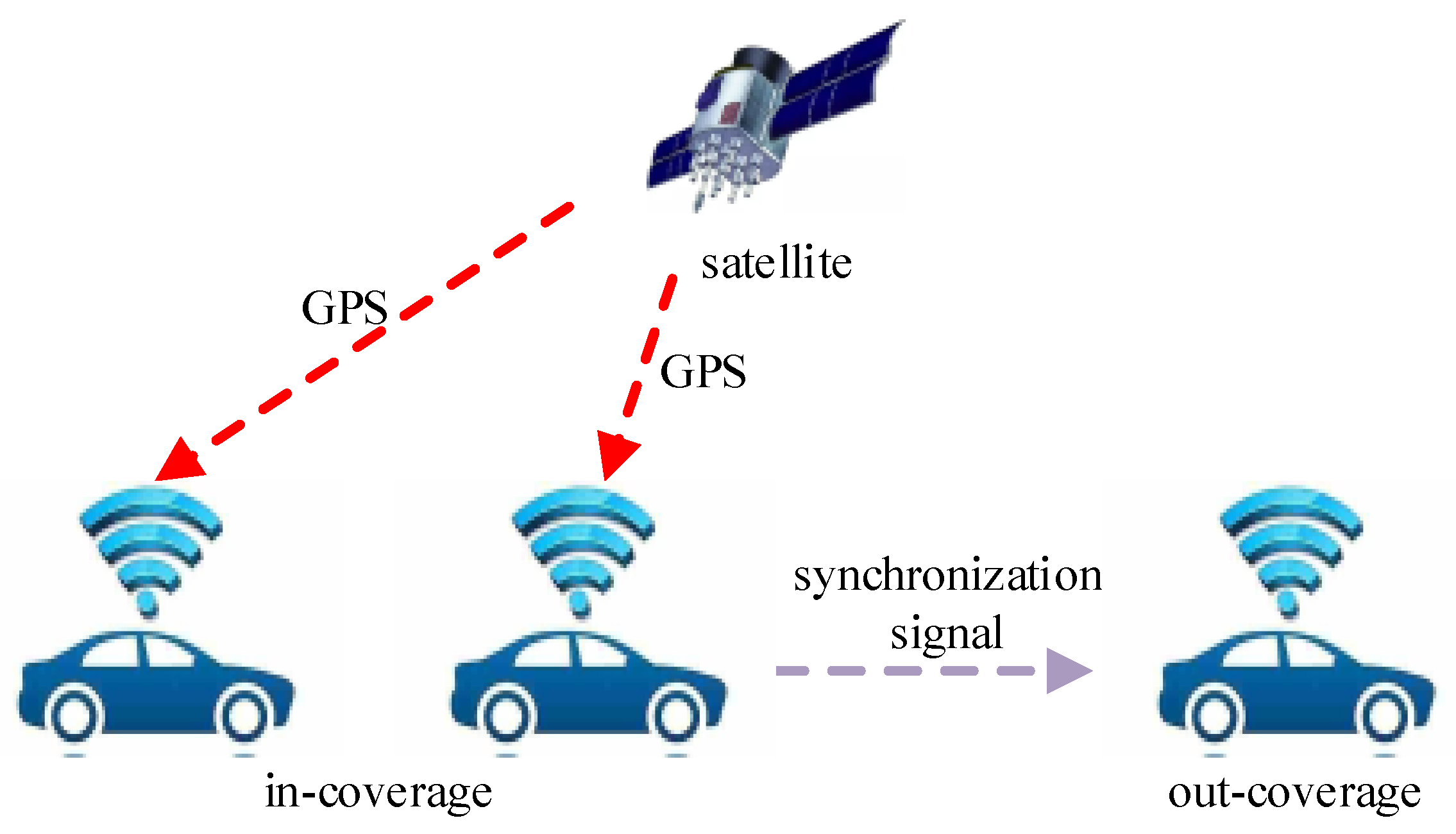
As the first C-V2X solution proposed by China Datang [4,7], LTE-V2X incorporates several enhancement technologies to address the challenges posed by high-speed node movement, low latency and high-reliability transmission requirements in V2X communication. Enhanced synchronization technology stands out as a key component of these enhancements [8,9]. As illustrated in Figure 1, synchronization enhancement technology enables nodes equipped with Global Navigation Satellite System (GNSS) modules to achieve direct time–frequency synchronization through the GNSS. However, since V2X scenarios can also include tunnels and densely populated high-rise urban areas where GNSS signals may be obstructed, a significant portion of nodes still relies on synchronization signals broadcasted by the upper synchronization source to achieve precise time–frequency synchronization. In such scenarios, the dependence on synchronization signals becomes crucial for ensuring accurate time–frequency synchronization.
In contrast to the traditional LTE cellular network system, the movement of communication nodes within the LTE-V2X system leads to changes in the channel state between these nodes over time. Regarding time synchronization in LTE-V2X, three main issues need to be addressed:
- V2X communication equipment utilizes Single Carrier Frequency Division Multiple Access (SC-FDMA) modulation, accompanied by low-transmission power. This necessitates the symbol timing synchronization algorithm at the receiver to set a low detection threshold, preventing the missed detection of the Primary Sidelink Synchronization Signal (PSSS). The On-Board Unit (OBU) antenna is typically mounted atop the vehicle, and the signal may be blocked by large vehicles or other obstacles during relative movement, leading to a deep fading of the SNR of the received signal.
- The high speed of relative movement between nodes poses significant challenges to timing synchronization. The frequency of the LTE-V2X system is considerably higher than that of the LTE cellular network, with relative speeds between nodes potentially reaching up to 240 km/h, resulting in a substantial Doppler frequency offset. The instability of the local oscillator between the transmitter and receiver introduces a considerable frequency deviation. A 1 ppm error, for instance, leads to a frequency offset of 5.91 kHz at a frequency of 5.91 GHz. These factors contribute to the emergence of ‘secondary peaks’ near the correct correlation peak, thereby affecting the Correct Detection Rate (CDR) process in synchronization.
- The cycle of LTE-V2X synchronization signals (160 ms) is 32 times that of LTE 4G synchronization signals (5 ms) and 4 times that of LTE Device-to-Device (D2D) synchronization signals (40 ms). When utilizing correlation calculation results, especially those involving multi-symbol accumulation, for symbol synchronization, the computational complexity significantly increases, leading to a reduction in synchronization efficiency. In scenarios such as connected vehicle networks, where sensitivity to latency is critical, improving the efficiency of time synchronization is of paramount importance.
Numerous timing synchronization methods have been proposed in the literature, encompassing both data-aided and blind detection schemes [10]. Blind detection methods leverage the specific frame structure in the orthogonal frequency division multiplexing (OFDM) system for symbol timing synchronization. Examples include the Cyclic Prefix (CP)-based maximum likelihood detection method [11], CP-based auto-correlation method [12] and minimum difference and difference square methods [13]. However, these methods may be less suitable for the LTE-V2X system due to their reliance on multiple OFDM symbol accumulations for improved performance and susceptibility to noise. Data-assisted methods comprise pilot-based auto-correlation [14] and pilot-based cross-correlation [15]. The auto-correlation method involves repeated pilot correlation in the received signal, and the cross-correlation method correlates the received signal’s pilot with the locally duplicated one. LTE-V2X employs the frequency domain Zadoff–Chu (ZC) sequence as the pilot, and the selection of the root sequence enhances the pilot’s resistance to frequency offset. Consequently, this article primarily investigates the symbol timing synchronization algorithm based on the pilot, specifically the PSSS.
Given the complexity of the communication environment and the unique frame structure in LTE-V2X, numerous scholars have proposed corresponding synchronization algorithms based on the PSSS. In [16], Bhamri et al. employed a selective summing function for correlated peaks detected, leveraging the continuous transmission feature of the PSSS in LTE-V2X. Spefificially, peaks detected in a subframe are added with peaks detedted in the same subframe at a known relative distance between the two PSSS symbols. Subsequently, another judgment was applied, significantly enhancing the algorithm’s performance in adverse channel conditions. However, in cases of an excessively large frequency offset, the “secondary peaks” within the primary peaks are prone to misjudgment, resulting in a failure of symbol timing synchronization. The study in [17] utilized the phase difference between the PSSS and the Sidelink Secondary Synchronization Signal (SSSS) to achieve a joint estimation of symbol timing synchronization and carrier frequency offset. This approach effectively mitigates the impact of multipath and Doppler frequency offset. In [18], the algorithm employed the accumulation of correlated results from multiple half-frames to enhance the robustness and accuracy of synchronization results. However, due to the Sidelink Synchronization Signal (SLSS) period being 160 ms, significantly larger than the 5 ms period of synchronization signals in the LTE downlink, improving the symbol timing algorithm through the enhanced algorithm of accumulating correlations across multiple subframes substantially increases its complexity. In [19], Vankayala et al. aimed to improve algorithm performance by accumulating results from the detection of multiple symbols. A drawback was the substantial computational workload. In [20], Zheng et al. adopted the block cross-correlation method, dividing the local signal and received signal into several blocks, performing separate correlations and then summing them. This enhances resistance to frequency offset. However, due to the cumulative effect of noise, its performance is poorer in low SNR conditions.
From these works, we can learn that existing symbol timing synchronization methods based on the PSSS have shortcomings, such as susceptibility to channel state variations and high complexity. Therefore, building upon the foundation of the aforementioned research, this paper proposes an improved symbol timing synchronization algorithm based on the PSSS. Our main contributions are outlined as follows:
- We investigate and analyze several commonly used time synchronization algorithms based on the PSSS. We perform theoretical analyses on aspects such as synchronization signal detection performance and algorithm complexity.
- We propose an improved symbol timing synchronization algorithm based on the PSSS, aiming to enhance the robustness and accuracy of synchronization signal detection in LTE-V2X. We conduct simulation analyses to compare its performance with existing algorithms, demonstrating effective improvement in robustness under high frequency offset and low SNR scenarios in vehicular networks.
- We establish a hardware-in-the-loop simulation platform and compare the performance of the proposed improved algorithm with other existing algorithms in different scenarios and vehicle speeds. We validate, in high-speed mobile scenarios, that the proposed algorithm maintains a high CDR even under low SNR conditions.
The remainder of this paper is organized as follows: First, we introduce the main properties of the PSSS in Section 2. In Section 3, we analyze the limitations of several existing symbol timing synchronization algorithms based on the PSSS. Building on this analysis, we propose an improved algorithm with the aim of enhancing the robustness and accuracy of synchronization signal detection in Section 4. Section 5 is dedicated to verifying the performance of the proposed improved algorithm through software simulation and hardware-in-the-loop simulation. Finally, in Section 6, we summarize our conclusions and provide a brief outlook on future work.
2. PSSS in LTE-V2X
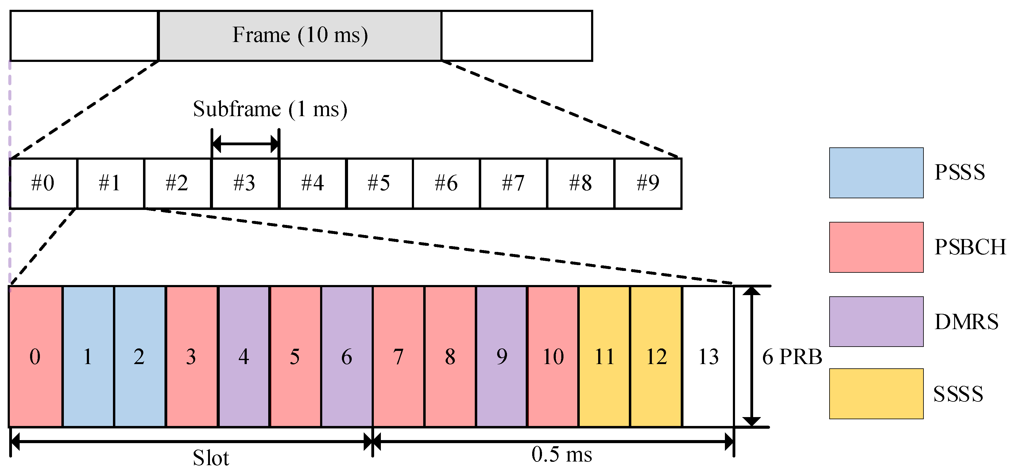
The LTE system’s physical layer is traditionally divided into the uplink and downlink. In contrast, the physical layer of LTE-V2X, known as the sidelink, has evolved based on LTE-D2D technology, inheriting most of the air interface characteristics [21]. To address the limitations of mobile terminal transmission performance, LTE-V2X employs SC-FDMA to convert frequency domain signals into time domain signals, mitigating the Peak-to-Average Power Ratio (PAPR) effect. Physical channels in LTE-V2X are categorized based on their functions, including broadcast, discovery, shared and control channels. Figure 2 illustrates the placement of the Sidelink Synchronization Signal (SLSS) in the physical sidelink broadcast channel (PSBCH).
To reduce the overhead of time–frequency resources, the period of the SLSS is 160 ms, which is much larger than the period of synchronization signals in LTE (5 ms). Meanwhile, the PSSS is transmitted in two adjacent SC-FDMA symbols in the same subframe.
The generation and nature of the synchronization signal is as follows. The SLSS carries 336 physical layer sidelink synchronization identifications , according to
where is the cell identification (ID) that indicates whether the terminal is covered, and the PSSS carries it. is the group identification that indicates the ID of the terminal, and it is taken by the SSSS.
The sequence used for the PSSS is generated from a frequency domain ZC sequence according to
where is the root index. If , , and if , .
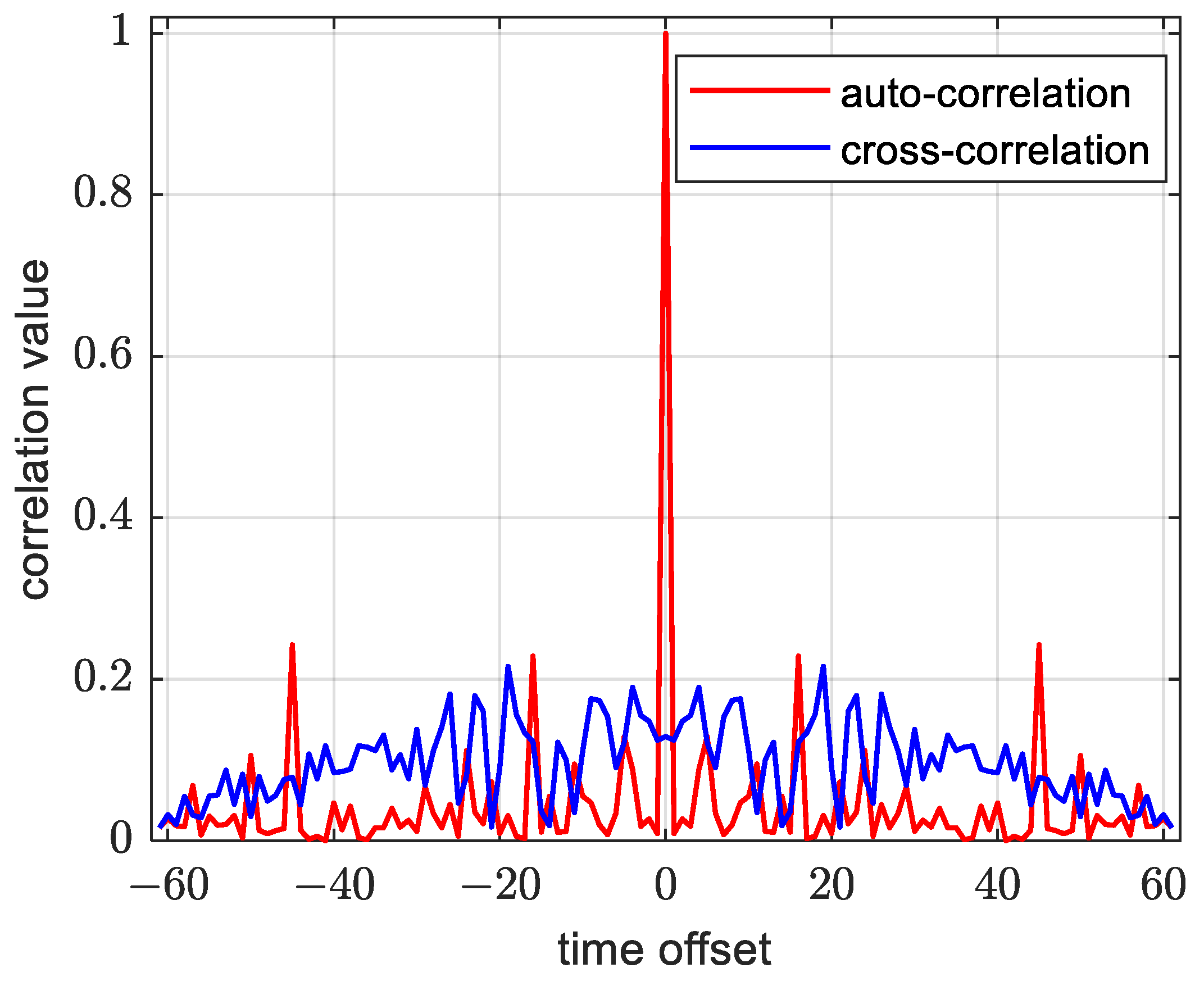
Due to the inherent properties of the ZC sequence, the PSSS exhibits excellent auto-correlation and cross-correlation characteristics, as illustrated in Figure 3 below. During auto-correlation operations on an identical PSSS, a prominent ‘peak’ is observed at the zero point, indicating a large correlation value. Conversely, when performing cross-correlation calculations for distinct main synchronization signals, the correlation value is nearly zero. These properties of the PSSS establish a robust foundation for its detection in the terminal. Furthermore, the PSSS possesses time domain symmetry, implying that its time domain representation is centrosymmetric. This particular property can be leveraged to reduce the complexity of the synchronization algorithm [22].
The mapping of the sequence to resource elements depends on the frame structure. In the frequency domain, a PSSS with a length of 62 is mapped to the middle six Resource Blocks (RB) in the time–frequency resource grid, that is, 72 sub-carriers and the 5 sub-carriers at the two ends are vacant as the guard interval. In the time domain, the PSSS is continuously transmitted on the second and third OFDM symbols.
3. Traditional PSSS-Based Time Synchronization Algorithm
3.1. PSSS-Based Time Domain Cross-Correlation Algorithm
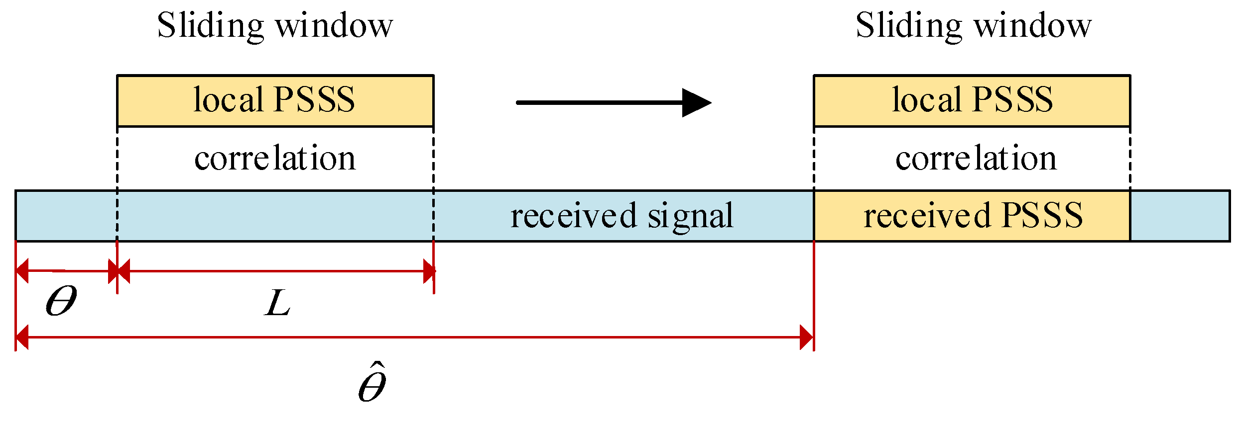
The traditional cross-correlation algorithm is a commonly used symbol synchronization method in the LTE system, and it can also be applied to the LTE-V2X system. This algorithm involves cross-correlating two distinct local synchronization signals with the received signal, which is intercepted by a sliding window, as illustrated in Figure 4. Subsequently, the algorithm performs a maximum likelihood decision to identify the correlation peak, allowing the determination of the local signal type and the Fast Fourier Transform (FFT) window position.
The cross-correlation value and maximum likelihood decision are defined as
where is the received signal, is the local PSSS of two types, is the start point of the sliding window and is the length of the sliding window.
The cross-correlation algorithm is straightforward to implement; however, its complexity can become unexpectedly high when dealing with long received signals or large sliding window lengths. In situations involving a significant frequency offset or low SNR, a ‘secondary peak’ may emerge near the correct peak position, leading to a failure in peak judgment. Consequently, the algorithm may struggle to adapt to the synchronization detection requirements of V2X.
3.2. PSSS-Based Time Domain Block Cross-Correlation Algorithm
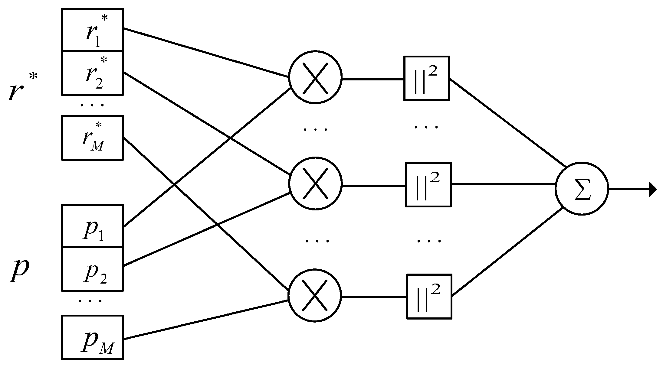
Due to the poor performance of the cross-correlation algorithm in a large frequency offset scenario, the literature [23] proposes the block cross-correlation algorithm, which reduces the length of the effective sliding window by dividing the received signal and the local pilot into several blocks to reduce the cumulative effect of frequency deviation. Figure 5 shows the algorithm flow. In the figure, “*” represents the conjugate operation and r* is the conjugate of the received signal, p represents the local pilot, and M is the number of blocks for the received signal and the local pilot. Each sequence is operated separately, and the modulus squared is superimposed.
According to Figure 5, the cross-correlation value can be calculated as
where M is the number of blocks and L3 = N/M is the length of each sequence. The starting point θ of the synchronization signal can be determined using Equation (4).
By reducing the cumulative effect offset frequency offset, the block cross-correlation algorithm can effectively resist the huge frequency offset. And in theory, the larger the number of blocks, the better the anti-frequency offset performance. However, as the number of blocks increases, the noise is also superimposed, resulting in poor performance of the algorithm under the condition of a low SNR. Consequently, the relative height of the correlation peaks decreases, and peak misalignment appears.
3.3. PSSS-Based Selective Summing Algorithm
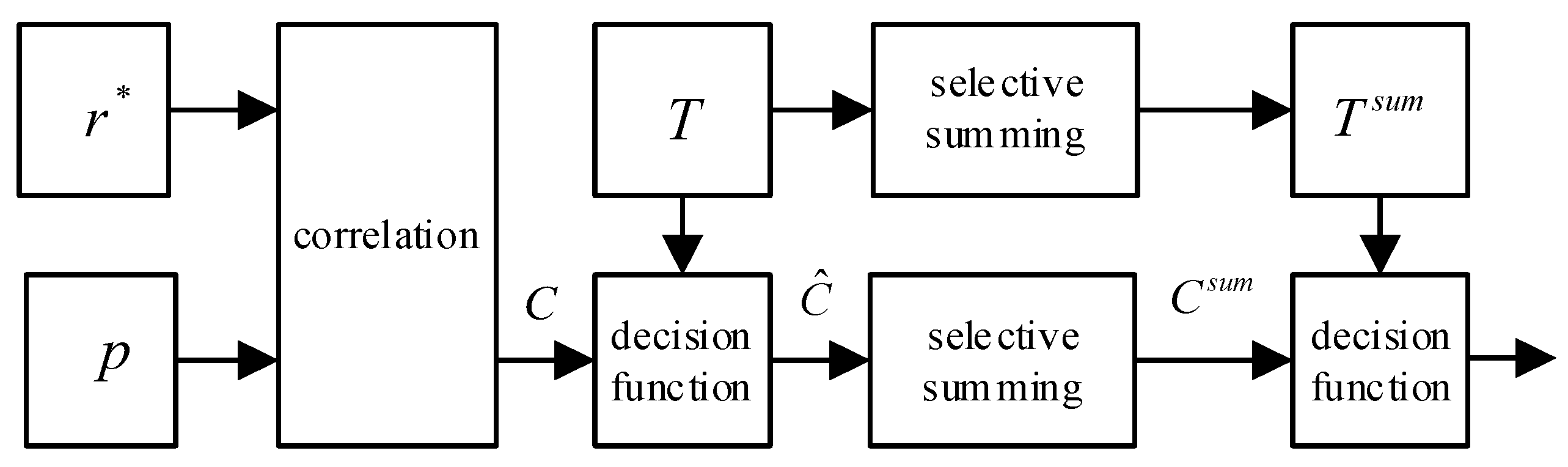
Considering that the PSSS is transmitted in two adjacent SC-FDMA symbols, a robust PSSS detection algorithm, namely the selective summing algorithm, is proposed in the literature [16]. This algorithm leverages the known relative distance between the two PSSS symbols at the receiver. Along with their respective detection thresholds, peaks detected in a subframe are summed with other peaks detected and their detection thresholds in the same subframe at the known relative distance, which is the relative distance between the two PSSS symbols. Subsequently, the new correlation result is compared with the new threshold value to obtain the final peak. Figure 6 illustrates the flow chart of the algorithm, where T represents the detection threshold.
According to Figure 6, the calculated correlation and threshold are defined as
where d is the relative distance of the two PSSS symbols and T represents the detection threshold.
The main idea of the selective summing algorithm is to utilize the known distance between two PSSSs to perform selective peak addition processing on the calculated correlation, thereby improving the performance of the algorithm under the condition of low SNR. However, when the propagation condition is bad (large frequency offset and/or rich multipath), a “secondary peak” appears near the correct peak. When the distance between the “secondary peaks” is equal to the distance between two PSSSs, the selective summing algorithm also adds those peaks to the wrong position, causing time synchronization failure.
4. Improved PSSS-Based Time Synchronization Algorithm
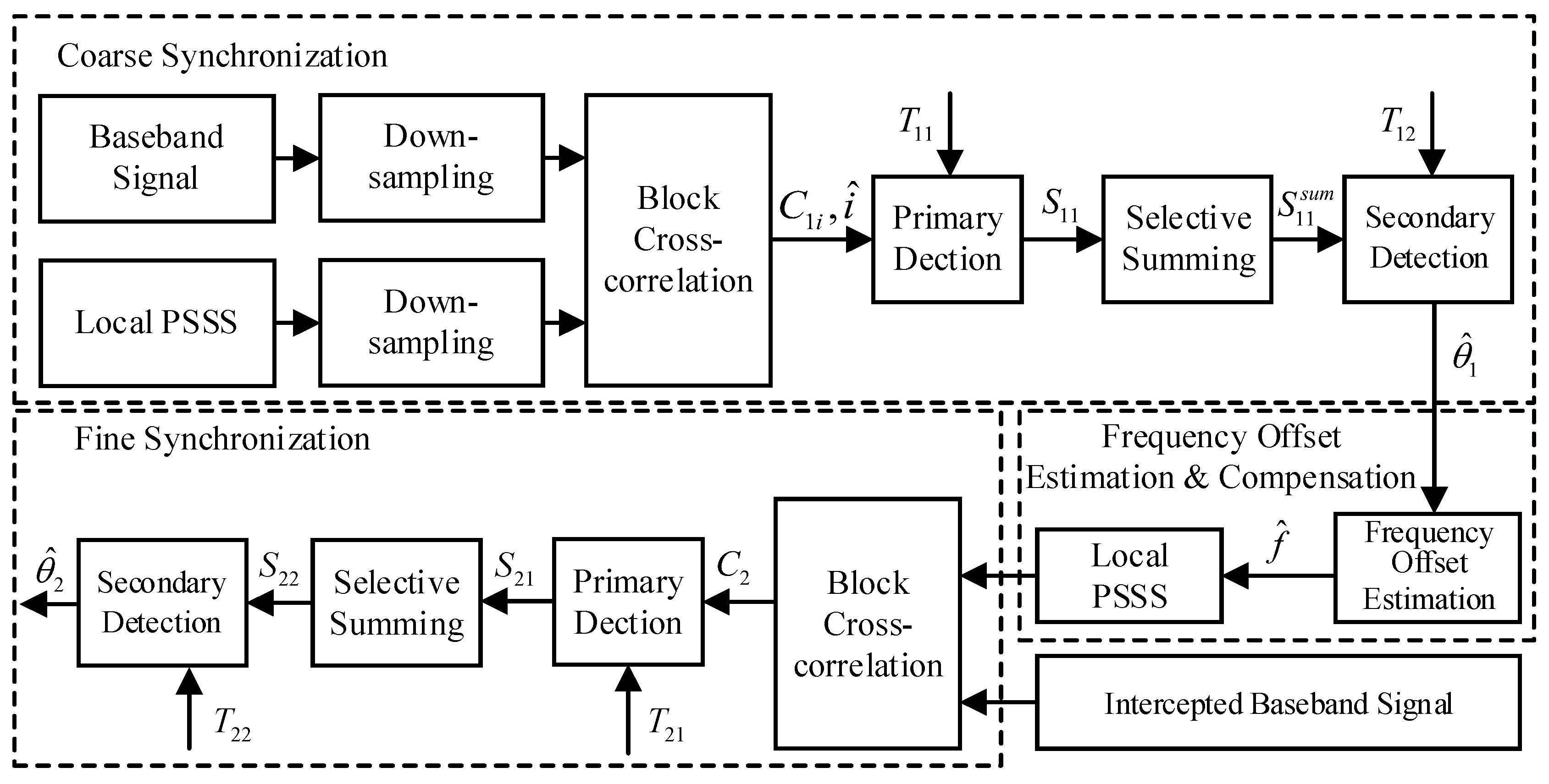
The improved algorithm proposed in this paper is divided into coarse synchronization, frequency offset estimation and fine synchronization, as shown in Figure 7.
The robustness and correctness of synchronization signal detection are improved from the following aspects while ensuring that the complexity of the algorithm is not too high:
- The block cross-correlation algorithm and selective summing algorithm are improved and merged in the existing symbol timing synchronization algorithm, and the threshold is designed to make it more robust to frequency offset and noise.
- After coarse synchronization, the local synchronization signal and the received synchronization signal are used to estimate the frequency offset, and the local synchronization signal is compensated, which significantly improves the resistance of the algorithm to frequency offset.
- Although the baseband signal is downsampled before coarse synchronization, the baseband signal is intercepted before fine synchronization, which significantly reduces the number of correlation operations at the receiving end and makes the algorithm less complex, ensuring that the reliability and accuracy of the algorithm are high.
4.1. Coarse Synchronization
The bandwidth is assumed to be 20 MHz, and the baseband sampling rate is set to 30.72 MHz. Considering the large synchronization signal period in LTE-V2X, the improved algorithm only takes 4,915,200 points for the baseband signal (one synchronization period) to perform time synchronization.
To reduce the computational complexity, two kinds of local synchronization signals are downsampled N times. To ensure that the amount of information is not lost, the number of the local synchronization signal points after downsampling should be greater than the length of the PSSS sequence (62 points) in the frequency domain, so the sampling multiple N = 32 is taken here.
The local PSSS and downsampled received signal (taking into account the time domain symmetry of the primary synchronization sequence, here the number of blocks is M = 2) are divided into several blocks, and each block of and is respectively correlated and superimposed to obtain two correlation values: . After that, the maximum likelihood decision is used to obtain the type of receiving synchronization signal . and the maximum likelihood decision are defined as
where represents the downsampled received signal, represents the downsampled local PSSS of a different type, represents the type of PSSS in the received signal obtained by the maximum likelihood decision, represents the number of blocks and is the length of each block sequence.
After comparing the correlated samples with the detection threshold , the coarse synchronization peak and can be expressed by the following equations:
where is the false alarm rate. The false alarm rate of detection is higher when increases. Since requires a second decision, to avoid missing the PSSS and improve the effectiveness of the second decision, is 0.2 here, so Equation (12) can be rewritten as
The values in equal to the relative distance between the two PSSSs are selected and added to obtain the summing peak value . Then, the coarse peak is obtained by comparing the correlated samples with the detection threshold . The above can be expressed as
To prevent “secondary peaks” in from being misjudged as the correct peak, the false alarm coefficient of the secondary decision threshold is set to 0.7, which effectively reduces the false alarm rate.
The coarse estimate point can be expressed as
4.2. Frequency Offset Estimation
The calculation of is based on the downsampled received signal and the local synchronization signal, so there is an error of from the actual position. Therefore, fine synchronization is required to complete the synchronization process, but due to the high frequency offset characteristics of the LTE-V2X communication scene, performing fine synchronization directly without any processing on the received signal can easily lead to TO or even fail the fine synchronization.
In this part, we use and frame struct to calculate the position of the Demodulation Reference Signal (DMRS) in the same frame of the broadcast channel and then extract them to estimate the frequency offset, and we preset the estimated frequency offset to the local synchronization signal to improve the accuracy and reliability of the fine synchronization.
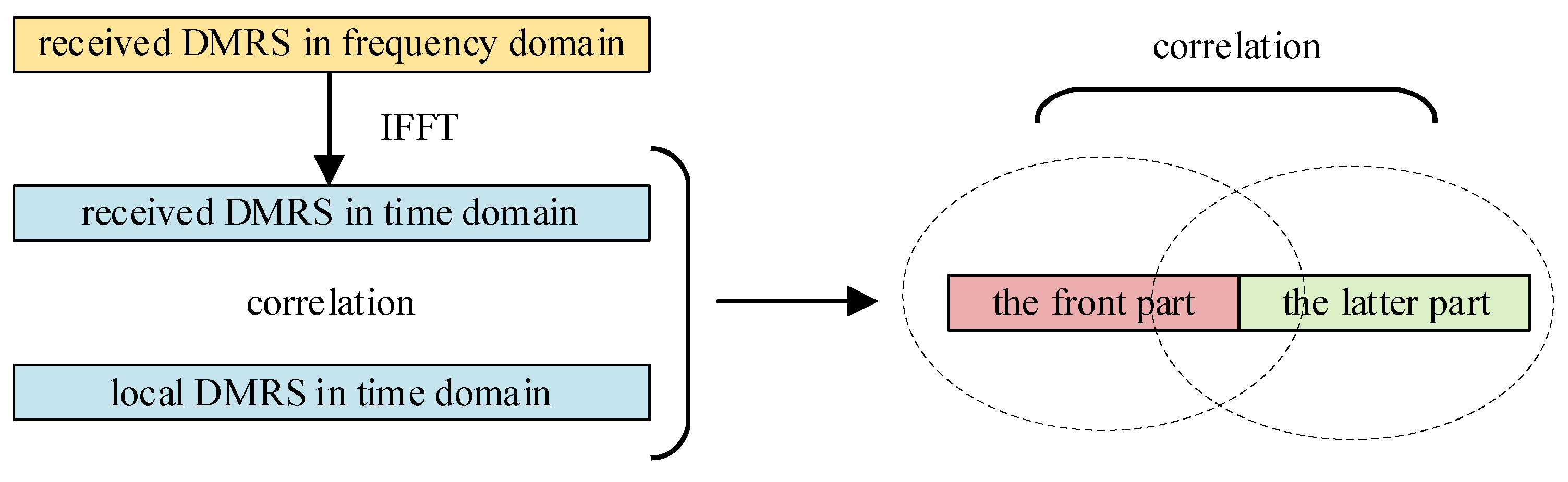
DMRS-based frequency offset estimation methods are mainly divided into the Adjacent DMRS-based algorithm [24] and the Half-symbol-based algorithm [25,26]. The Adjacent DMRS-based algorithm estimates the frequency offset by calculating the phase difference between adjacent DMRSs. Its range is related to the minimum interval of the DMRS in the time domain. The Half-symbol-based algorithm estimates the frequency offset by comparing the phase changes in each half of a single DMRS in the time domain. As shown in Figure 8, the correction range is equal to the subcarrier spacing.
In the LTE-V2X system, the high communication frequency point and the relative speed between nodes make the channel change rapidly over time. Assuming that the relative velocity between cars is 300 km/h, the communication frequency point is 5915 MHz. Therefore, the maximum Doppler frequency deviation is about 1643 Hz, and the channel coherence time is 0.1 ms. The period of the SC-FDM symbol is 0.07 ms, which is greater than the channel coherence time of V2X. Therefore, it can be considered that the channel is approximate within one SC-FDM symbol. However, the Adjacent DMRS-based algorithm uses an adjacent DMRS for frequency offset estimation and spans three SC-FDM symbols. Hence, its accuracy is lower than that of the Half-symbol-based algorithm, which uses one DMRS symbol frequency offset estimation. In summary, this paper chooses the Half-symbol-based algorithm to estimate the frequency offset after coarse synchronization.
The DMRS in the PSBCH is located on the 5th, 7th and 10th SC-FDMA symbols. The three received DMRSs are extracted according to the specific PSBCH frame struct and are cross-correlated successively with the local DMRS duplicate. The frequency offset estimation using the Half-symbol-based algorithm can be expressed as
where is the received DMRS, is the local DMRS duplicate, represents different SC-FDM symbols and is the number of FFT points.
The local synchronization signal that presets the estimated frequency offset can be expressed as
4.3. Fine Synchronization
The has an error of ±N samples, so fine synchronization is required to obtain an accurate frame start position. First, the baseband signal is intercepted near the coarse synchronization point. The range is a complete PSBCH physical channel. Similar to the coarse synchronization step, it performs a block cross-correlation algorithm and peak detection to obtain a fine synchronization peak. The process can be expressed as follows:
where is the result of block cross-correlation and is the threshold of it.
The values in equal to the relative distance between the two PSSSs are selected and added to obtain the selective summing peak. The second decision is performed with a larger threshold to obtain the secondary fine synchronization peak , that is, the fine synchronization point. The above can be expressed as follows:
Finally, the fine estimate point can be expressed as
5. Results and Discussion
5.1. Software Simulation
This section presents the corresponding simulation works to verify the performance of the improved timing synchronization algorithm. An LTE-V2X timing synchronization simulation system is built, and the performances of the cross-correlation algorithm, the block cross-correlation algorithm, the selective summing algorithm and the improved algorithm are compared and analyzed under different frequency offsets.
The simulation parameters are shown in Table 1. ε denotes the normalized frequency offset. When the positions of the two precise synchronization points calculated by each algorithm and the synchronization signal are within five sampling points, the synchronization is determined to be successful, and the CDR of successful synchronization in 1000 frames is finally counted.
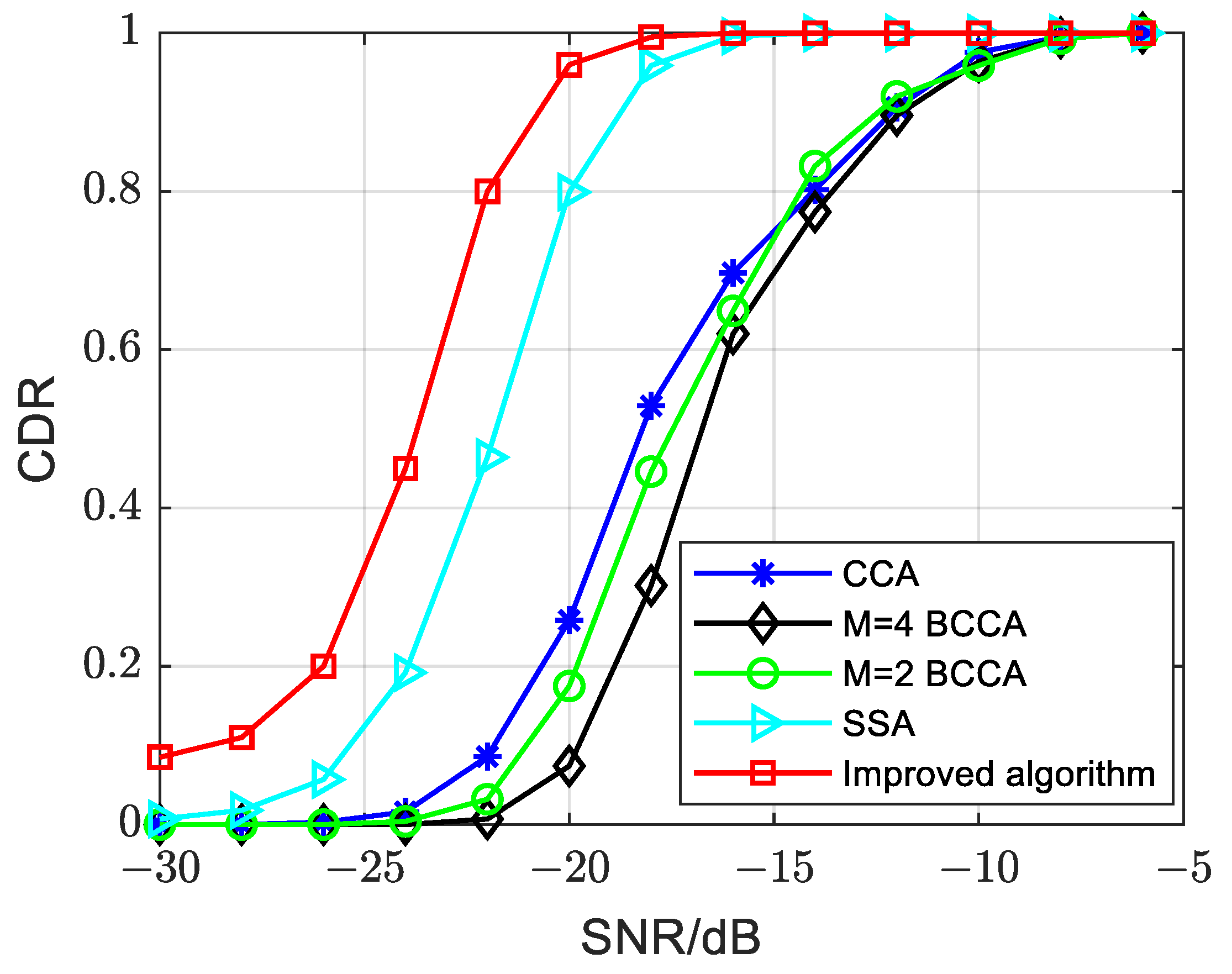
Figure 9 compares the performance of the improved algorithm and the traditional algorithms under the Additive White Gaussian Noise (AWGN) channel when the normalized frequency offset is 0. In the figure, CCA, BCCA and SSA refer to the cross-correlation algorithm, block cross-correlation algorithm and selective summing algorithm in Section 3, respectively. M represents the number of blocks for the BCCA. Through the comparison of these algorithms, we can make conclusions as follows:
- The proposed improved algorithm in this paper exhibits significant improvement in PSSS detection compared to other algorithms. The enhancement is approximately 6–8 dB compared to the CCA, M = 4 and M = 2 BCCAs and around 2 dB compared to the SSA. The improved algorithm maintains a CDR close to 0.9 even at −20 dB.
- In comparison to the BCCA and CCA, the SSA demonstrates superior PSSS detection performance with an improvement of approximately 4–6 dB. The SSA achieves a CDR close to 0.9 at an SNR of −18 dB.
- The M = 2 and M = 4 BCCAs perform similarly to the CCA when the SNR is greater than −15 dB. However, when the SNR is below −15 dB, the performance of the M = 4 BCCA is 2–3 dB worse than that of the M = 2 BCCA and the CCA. This discrepancy is attributed to the increased number of blocks leading to noise superposition, resulting in poor synchronization performance at a low SNR.
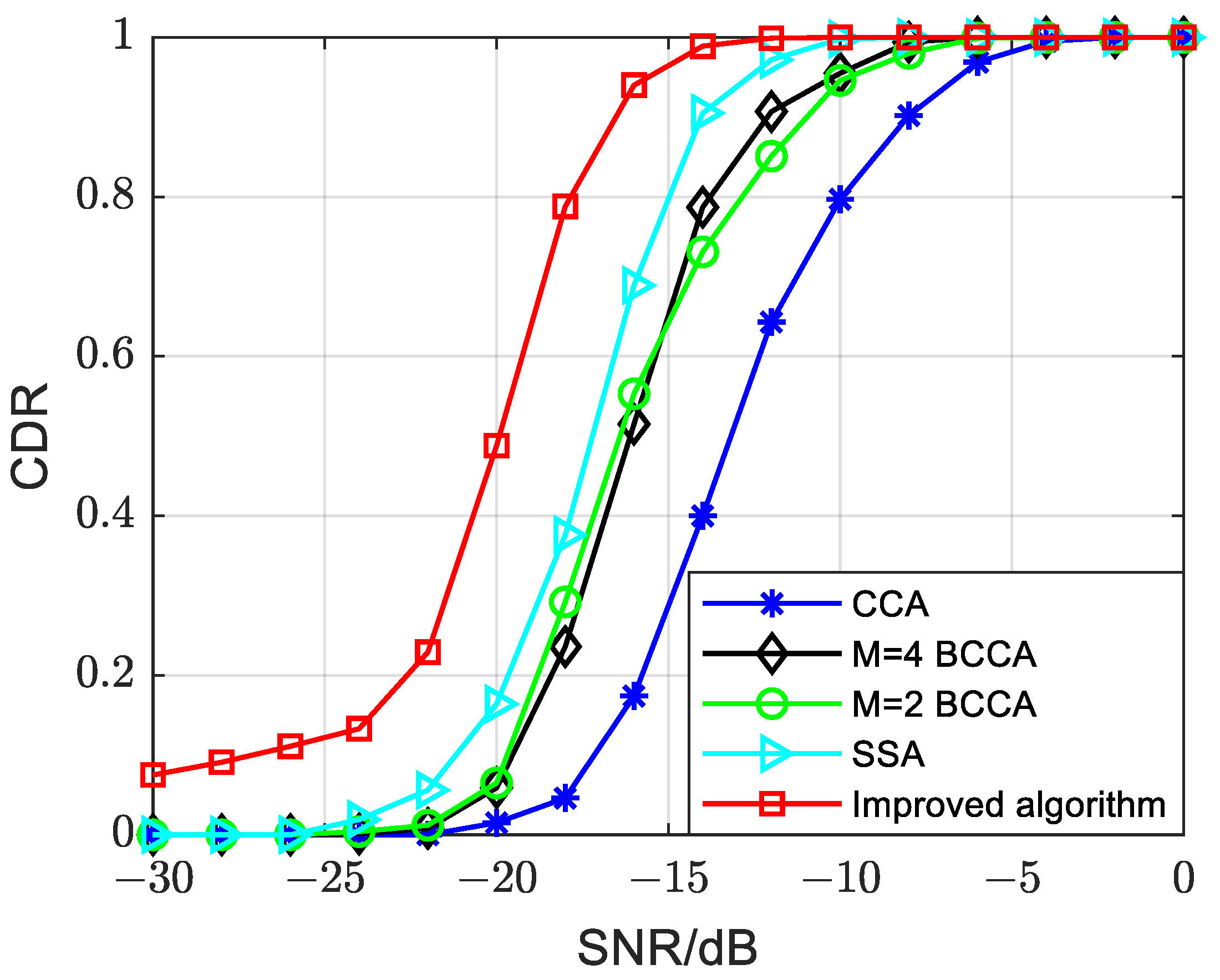
In Figure 10, we compare the performance of the improved algorithm and the other traditional algorithms under the AWGN channel when the normalized frequency offset is set to 0.5. From the simulation results, we can make conclusions as follows:
- The improved algorithm demonstrates superior PSSS detection performance compared to other algorithms, with an approximate 3 dB improvement over the SSA and about a 4 dB improvement over the M = 4 and M = 2 BCCAs. Additionally, the improved algorithm maintains a CDR close to 0.9 at −16 dB.
- For the M = 4 and M = 2 BCCAs, their performance surpasses that of the CCA. Under various SNRs, the CDR of the BCCA consistently exceeds that of the CCA. This is attributed to the block, which reduces the cumulative effect of frequency offset.
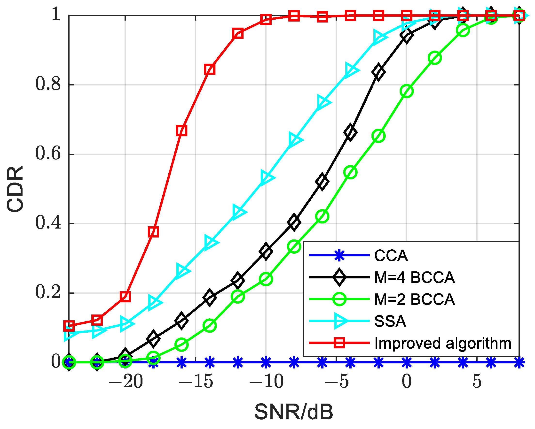
Figure 11 illustrates the performance of each algorithm under the AWGN channel with a normalized frequency offset of 1. The conclusions are as follows:
- The improved algorithm demonstrates superior resistance to a high frequency offset compared to other algorithms. Specifically, it achieves a performance improvement of up to 14 dB compared to the M = 4 and M = 2 BCCAs. In comparison to the SSA, the improvement reaches 10 dB. The improved algorithm attains a CDR of 0.9 at −14 dB.
- The CCA loses its ability to detect the PSSS when the normalized frequency offset reaches 1. The CDR of the CCA remains consistently at 0.
5.2. Hardware-in-the-Loop Simulation
This paper establishes a hardware-in-the-loop simulation platform to further validate the performance of the improved algorithm, offering the following advantages:
- Efficient testing: The hardware-in-the-loop simulation overcomes the time-consuming nature and limited scope of field testing, allowing for a comprehensive analysis of communication performance in various channel conditions within a shorter timeframe. It provides valuable insights and corresponding deployment suggestions.
- Accuracy and reliability: In comparison to software simulation, the hardware-in-the-loop simulation platform utilizes an actual signal source as the transmitter, ensuring more accurate and reliable results.
- Versatility: The channel emulator supports the import of channel models, making use of models obtained by various research institutes. This versatility enhances the adaptability of the simulation platform.
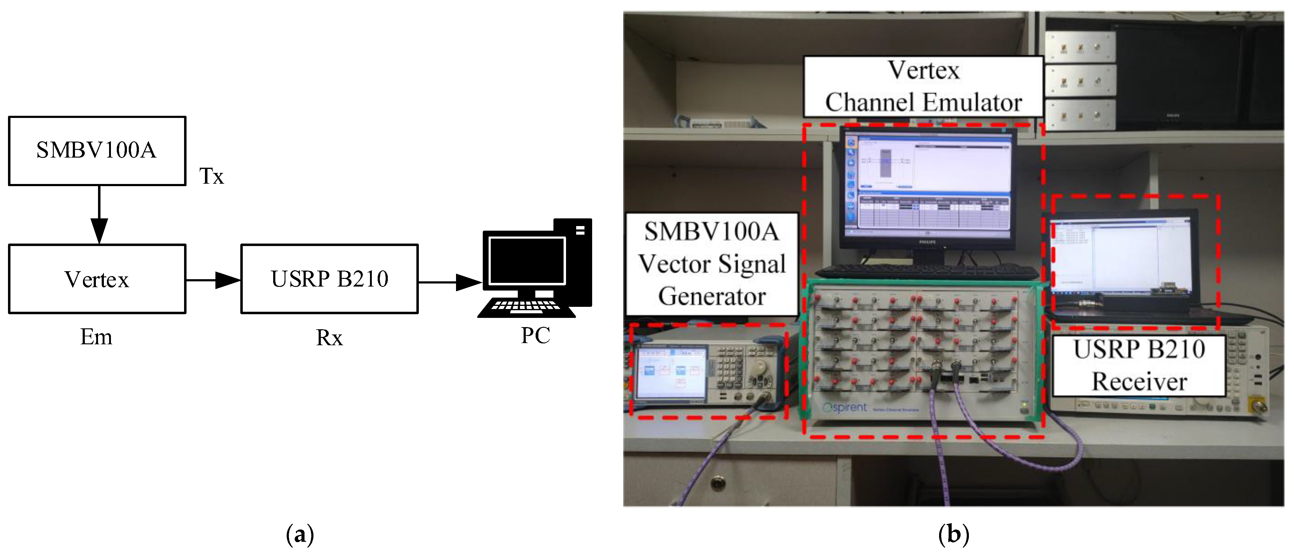
Figure 12 illustrates the hardware-in-the-loop simulation platform, comprising the SMBV100A vector signal generation source from Rhodes and Schwartz as the transmitter, the Vertex channel emulator from Spirent and the receiver consisting of the Universal Software Radio Peripheral (USRP) B210 and a Personal Computer (PC). During the hardware-in-the-loop simulation, the configured LTE-V2X signal is fed into the SMBV100A and continuously transmitted to the Vertex. Simultaneously, the USRP B210 receives the LTE-V2X signal passing through the channel emulator. The PC processes the collected LTE-V2X signal from the USRP, facilitating a performance comparison of symbol time synchronization under different channel conditions.
Due to the power limitation of the signal entering the channel emulator, the transmitter configuration and the LTE-V2X signal we generated, shown in Table 2, comply with 3GPP specifications except for transmission power.
The channel models we used are shown in Table 3 below, which are defined in 3GPP specification TR 36.885 [27]. Considering the diversity of V2X propagation channels, this paper selects high-speed line-of-sight (LOS) and urban non-line-of-sight (NLOS) models. It considers three different speeds of 0 km/h, 50 km/h and 120 km/h, as Table 3 shows below.
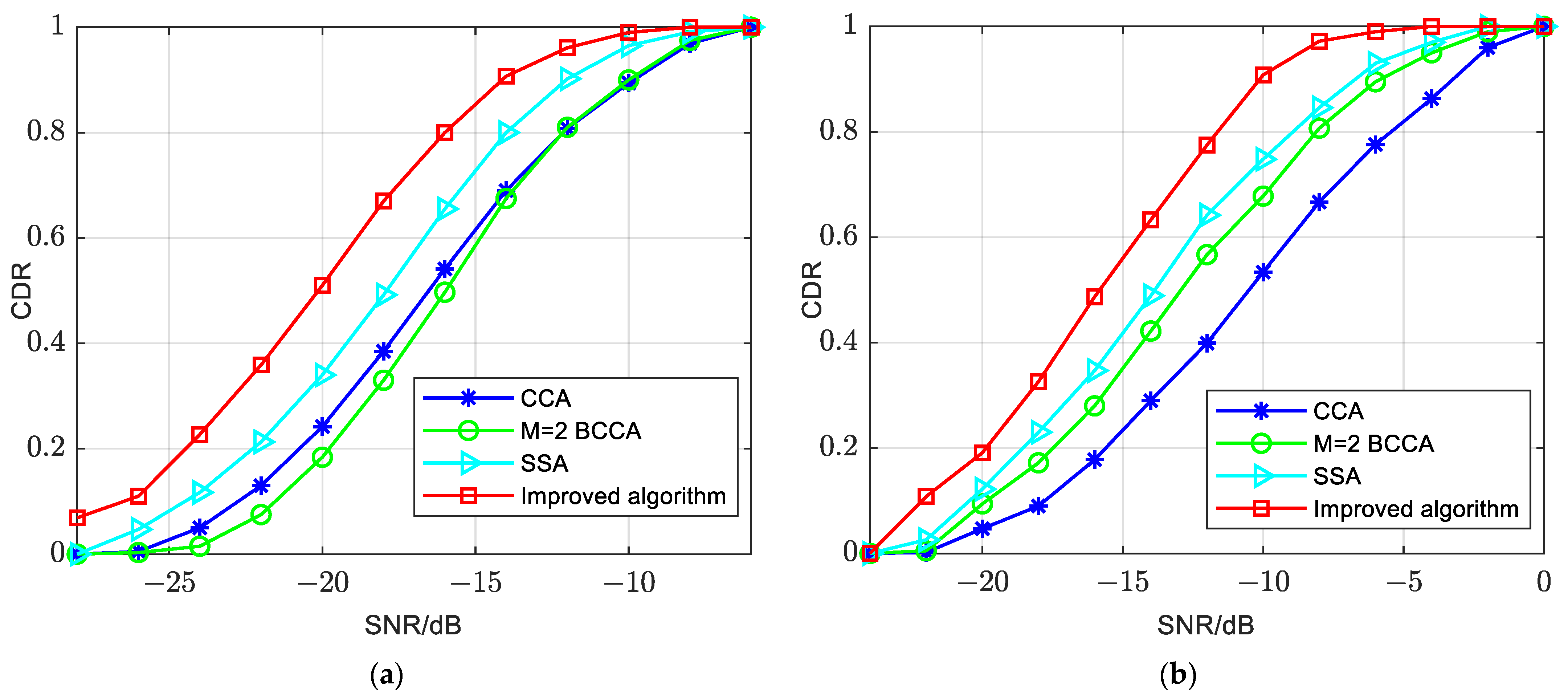
Figure 13 illustrates the performance of the improved algorithm and the traditional algorithms under different vehicle velocities in a Highway-LOS scenario. In Figure 13a, the velocity is 0 km/h, and in Figure 13b, the velocity is 120 km/h. From these simulation results, the following conclusions can be made:
- The improved algorithm enhances PSSS detection performance when the velocity is 0 km/h in this scenario. The improved algorithm can maintain a CDR close to 0.9 at −14 dB, the SSA achieves a CDR of 0.9 at −12 dB, and the M = 2 BCCA and CCA reach a CDR of 0.9 at −10 dB. Therefore, the SSA is approximately 2 dB worse than the improved algorithm, and the M = 2 BCCA and CCA are about 4 dB worse than the improved algorithm.
- The improved algorithm also enhances PSSS detection performance when the velocity is 120 km/h. The improved algorithm can maintain a CDR close to 0.9 at −10 dB. In contrast, the SSA achieves a CDR of 0.9 at −7 dB, which is about 3 dB worse than the improved algorithm.
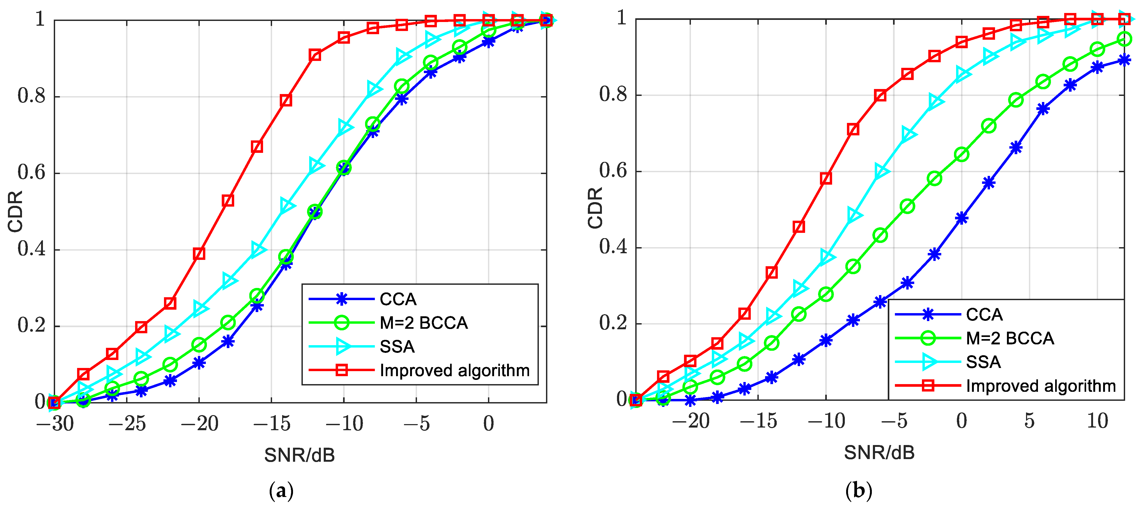
Figure 14 depicts the performance of the improved algorithm and traditional algorithms in the Urban-NLOS scenario. In Figure 14a, the velocity is 0 km/h, and in Figure 14b, the velocity is 50 km/h. From these simulation results, the following observations can be made:
- The improved algorithm appears to have better PSSS detection performance when the velocity is 0 km/h in this scenario. It maintains a CDR close to 0.9 at −12 dB. In contrast, the SSA achieves a CDR of 0.9 at −9 dB, indicating a 3 dB performance gap compared to the improved algorithm. The M = 2 BCCA and CCA achieve a CDR close to 0.9 at −2 dB, highlighting a 10 dB degradation compared to the improved algorithm.
- The improved algorithm also sustains superior PSSS detection performance when the velocity is 50 km/h in this scenario. At a velocity of 50 km/h, the improved algorithm maintains a CDR close to 0.9 at −2.5 dB. Conversely, the SSA achieves a CDR close to 0.9 at 2 dB, reflecting a performance gap of approximately 4.5 dB compared to the improved algorithm.
6. Conclusions
In this paper, we proposed a robust symbol timing synchronization algorithm based on the PSSS for the LTE-V2X communication scenario. Initially, we conducted an analysis of the advantages and disadvantages of existing timing synchronization algorithms. Building upon this analysis, we introduced an improved symbol timing synchronization algorithm, comprising three key steps: coarse synchronization, frequency offset estimation and fine synchronization. By integrating algorithms, designing decision thresholds and compensating for frequency offset, the proposed approach effectively enhances the algorithm’s robustness in scenarios characterized by high frequency offsets and low SNRs.
The simulation results demonstrate the superior performance of the improved algorithm compared to traditional methods such as cross-correlation, block cross-correlation and selective summing, particularly under conditions of high frequency offsets and low SNRs. In an AWGN channel with a normalized frequency offset of 1, the improved algorithm achieves a detection accuracy of 90% at −14 dB and 100% at −10 dB, meeting the stringent detection requirements for vehicular networks. This solution presents an effective approach to symbol timing synchronization in LTE-V2X.
Furthermore, we constructed a hardware-in-the-loop simulation platform to comprehensively compare and analyze the performance of the improved algorithm and existing algorithms under various vehicle speeds and scenarios. In high-speed moving scenarios, such as Urban-NLOS and Highway-LOS, the improved algorithm exhibits outstanding PSSS detection performance. Even under challenging low SNR conditions, the CDR of the improved algorithm consistently surpasses that of other algorithms.
Regarding future work, based on the research outlined in this paper, further investigations can be pursued in the following three aspects:
- Refinement of frequency offset estimation algorithms: Although this paper achieved coarse estimation of the frequency offset using a semi-symbol-based frequency offset estimation algorithm, there remains room for improvement. The inherent ±N error between the coarse synchronization point and the ideal synchronization point introduces a certain level of error in the frequency offset estimation. Therefore, future efforts should focus on exploring and developing more accurate frequency offset estimation algorithms to obtain precise frequency offset values.
- Enhancement of the SSSS detection algorithm: This paper primarily focused on researching and improving the primary synchronization signal detection algorithm. However, since the detection performance of the primary synchronization signal significantly influences overall synchronization signal detection, future work could delve into the development of a robust detection algorithm for secondary synchronization signals. Enhancing the algorithm to detect the SSSS can contribute to an overall improvement in synchronization signal detection performance.
- Symbol timing synchronization algorithm for 5G NR-V2X: NR-V2X has evolved from LTE-V2X, with the time–frequency resource definition for NR-V2X, having a subcarrier spacing of 15 kHz, being essentially similar to LTE-V2X. The difference lies in the fact that, in LTE-V2X, a 1 ms subframe contains two slots, and each time slot comprises 7 symbols. However, in NR-V2X with a subcarrier spacing of 15 kHz, a 1 ms subframe contains one slot, and the time slot consists of 14 symbols. Similar to LTE-V2X, the sidelink D2D link is also utilized in NR-V2X systems. Therefore, existing synchronization algorithms still hold reference value for NR-V2X. However, to support advanced applications (autonomous driving, vehicle platooning, etc.), NR-V2X introduces some new features, such as a flexible frame structure and the use of m-sequences to generate primary synchronization signals instead of ZC sequences. Hence, it is necessary to explore corresponding algorithms for NR-V2X systems based on the foundation of LTE-V2X timing synchronization algorithms.
Author Contributions
Conceptualization, J.Z. and B.C.; Data curation, J.Z.; Formal analysis, B.C., J.Q., L.Z., Z.W. and L.L.; Funding acquisition, L.L.; Investigation, B.C., L.Z., Z.W. and L.L.; Methodology, J.Z., B.C., J.Q., L.Z., Z.W. and L.L.; Project administration, B.C., J.Q. and L.L.; Software, J.Z. and B.C.; Supervision, B.C.; Validation, J.Z.; Visualization, J.Z.; Writing—original draft preparation, J.Z.; Writing—review and editing, J.Z., B.C., J.Q., L.Z., Z.W. and L.L. All authors have read and agreed to the published version of the manuscript.
Funding
This research was funded by the National Natural Science Foundation of China, grant number 61931001.
Data Availability Statement
All data are presented in this paper.
Conflicts of Interest
Liu Liu, as the corresponding author of this article, is employed by Beijing Jiaotong University, while Qiu Jiahui and Chen Bin are employed by China United Network Communications Group Co., Ltd. The other authors declared that they do not have any conflicts of interest. The authors hereby agree to submit this version of the article to Computers at MDPI and declare no conflicts of interest.
References
- Chen, S.; Shi, Y.; Hu, J. Cellular Vehicle to Everything (C-V2X): A Review. Bull. Natl. Nat. Sci. Found. China 2020, 34, 179–185. [Google Scholar] [CrossRef]
- Saad, M.M.; Khan, M.T.R.; Shah, S.H.A.; Kim, D. Advancements in Vehicular Communication Technologies: C-V2X and NR-V2X Comparison. IEEE Commun. Mag. 2021, 59, 107–113. [Google Scholar] [CrossRef]
- Chen, S.; Hu, J.; Shi, Y.; Zhao, L.; Li, W. A Vision of C-V2X: Technologies, Field Testing, and Challenges with Chinese Development. IEEE Internet Things J. 2020, 7, 3872–3881. [Google Scholar] [CrossRef]
- Chen, S.; Hu, J.; Shi, Y.; Zhao, L. Technologies, standards and applications of LTE-V2X for vehicular networks. Telecommun. Sci. 2018, 34, 1–11. [Google Scholar]
- Hur, D.; Lee, D.; Oh, J.; Won, D.; Song, C.; Cho, S. Survey on Challenges and Solutions of C-V2X: LTE-V2X Communication Technology. In Proceedings of the 2023 Fourteenth International Conference on Ubiquitous and Future Networks (ICUFN), Paris, France, 4–7 July 2023; pp. 639–641. [Google Scholar] [CrossRef]
- Gyawali, S.; Xu, S.; Qian, Y.; Hu, R.Q. Challenges and Solutions for Cellular Based V2X Communications. IEEE Commun. Surv. Tutor. 2021, 23, 222–255. [Google Scholar] [CrossRef]
- Chen, S.; Hu, J.; Shi, Y.; Zhao, L. LTE-V: A TD-LTE-Based V2X Solution for Future Vehicular Network. IEEE Internet Things J. 2016, 3, 997–1005. [Google Scholar] [CrossRef]
- The 3rd Generation Partnership Project. Evolved Universal Terrestrial Radio Access (E-UTRA), Physical Layer Procedures: TS 36.213 v14.2.0; 3GPP Support Office: Sophia Antipolis Valbonne, France, 2017; Available online: https://www.etsi.org/deliver/etsi_ts/136200_136299/136213/14.02.00_60/ts_136213v140200p.pdf (accessed on 27 December 2023).
- The 3rd Generation Partnership Project. Physical Layer Procedures: TS36.331 v.14.5.1; 3GPP Support Office: Sophia Antipolis Valbonne, France, 2018; Available online: https://www.etsi.org/deliver/etsi_ts/136200_136299/136212/14.05.01_60/ts_136212v140501p.pdf (accessed on 27 December 2023).
- Gul, M.M.U.; Ma, X.; Lee, S. Timing and Frequency Synchronization for OFDM Downlink Transmissions Using Zadoff-Chu Sequences. IEEE Trans. Wirel. Commun. 2015, 14, 1716–1729. [Google Scholar] [CrossRef]
- van de Beek, J.J.; Sandell, M.; Borjesson, P.O. ML estimation of time and frequency offset in OFDM systems. IEEE Trans. Signal Process. 1997, 45, 1800–1805. [Google Scholar] [CrossRef]
- Park, B.; Cheon, H.; Ko, E.; Kang, C.; Hong, D. A blind OFDM synchronization algorithm based on cyclic correlation. IEEE Signal Process. Lett. 2004, 11, 83–85. [Google Scholar] [CrossRef]
- Zhang, D.M.; Li, X.; Chen, J.T. Research on Timing Synchronization Algorithm of Primary Synchronization Signal in 5G System. Study Opt. Commun. 2019, 3, 59–64. [Google Scholar]
- Nassralla, M.H.; Mansour, M.M.; Jalloul, L.M. A Low-Complexity Detection Algorithm for the Primary Synchronization Signal in LTE. IEEE Trans. Veh. Technol. 2016, 65, 8751–8757. [Google Scholar] [CrossRef]
- Abdzadeh-Ziabari, H.; Zhu, W.-P.; Swamy, M.N.S. Joint Maximum Likelihood Timing, Frequency Offset, and Doubly Selective Channel Estimation for OFDM Systems. IEEE Trans. Veh. Technol. 2018, 67, 2787–2791. [Google Scholar] [CrossRef]
- Bhamri, A.; Li, Z.; Lindh, L.; Ribeiro, C. Primary synchronization signal detection method for device-to-device in LTE-Rel 12 and beyond. In Proceedings of the 2015 IEEE 82nd Vehicular Technology Conference (VTC2015-Fall), Boston, MA, USA, 6–9 September 2015; IEEE: Piscataway, NJ, USA, 2015; pp. 1–5. [Google Scholar]
- You, Y.-H.; Song, H.-K. Sequential Detection of Cyclic Prefix Mode, Sidelink Synchronization Signal, and Frequency Offset for LTE Device-to-Device Networks. IEEE Trans. Ind. Inform. 2020, 17, 3982–3991. [Google Scholar] [CrossRef]
- Du, S. The Synchronization Techniques in the LTE-V2X System. Master’s Thesis, University of Electronic Science and Technology of China, Chengdu, China, 2018. [Google Scholar]
- Vankayala, S.K.; Akhtar, J.; Krishnan, K.A.; Sah, A.K. Accelerated Detection Schemes for PSS in 5G-NR. In Proceedings of the 2020 IEEE 3rd 5G World Forum (5GWF), Bangalore, India, 10–12 September 2020; pp. 460–466. [Google Scholar] [CrossRef]
- Zheng, R.; Wang, X.; Pan, W.; Chen, X. Research and simulation on synchronization algorithm of PSS in a 5G system based on block cross-coirelation. J. Southeast Univ. (Engl. Ed.) 2021, 37, 245–250. [Google Scholar] [CrossRef]
- Molina-Masegosa, R.; Gozalvez, J. LTE-V for Sidelink 5G V2X Vehicular Communications: A New 5G Technology for Short-Range Vehicle-to-Everything Communications. IEEE Veh. Technol. Mag. 2017, 12, 30–39. [Google Scholar] [CrossRef]
- Berggren, F.; Popović, B.M. Primary Synchronization Signal for D2D Communications in LTE-Advanced. IEEE Commun. Lett. 2015, 19, 1241–1244. [Google Scholar] [CrossRef]
- Morelli, M.; Moretti, M. A Robust Maximum Likelihood Scheme for PSS Detection and Integer Frequency Offset Recovery in LTE Systems. IEEE Trans. Wirel. Commun. 2016, 15, 1353–1363. [Google Scholar] [CrossRef]
- Qualcomm Incorporated. DMRS Enhancements for V2V PSCCH and PSSCH: 3GPP R1-164417. In Proceedings of the 3GPP TSG RAN WG1 Meeting#85, Nanjing, China, 23–27 May 2016; p. 7. [Google Scholar]
- CATT. Discussion on Resource Selection Mechanism in PC5-Based V2V: 3GPP R1-164201. In Proceedings of the 3GPP TSG RAN WG1 Meeting#85, Nanjing, China, 23–27 May 2016. [Google Scholar]
- LG Electronics. Revision of WI: Support for V2V Services Based on LTE Sidelink: RP-160649. In Proceedings of the 3GPP TSG RAN Meeting #71, Göteborg, Sweden, 7–10 March 2016. [Google Scholar]
- The 3rd Generation Partnership Project. Study on LTE-Based V2X Services: 3GPP TR 36.885 v14.4.0; 3GPP Support Office: Sophia Antipolis Valbonne, France, 2016.
Figure 1.
LTE-V2X synchronization scenario.

Figure 2.
SLSS in PSBCH.

Figure 3.
Auto-correlation and cross-correlation value of PSSS.

Figure 4.
Traditional cross-correlation algorithm.

Figure 5.
Block cross-correlation algorithm flow diagram.

Figure 6.
Selective summing algorithm flow diagram.

Figure 7.
Flow chart of improved time synchronization algorithm.

Figure 8.
Flow chart of Half-symbol-based algorithm.

Figure 9.
Performance of different symbol timing synchronization algorithms in AWGN channels when ε = 0.
Figure 9.
Performance of different symbol timing synchronization algorithms in AWGN channels when ε = 0.

Figure 10.
Performance of different symbol timing synchronization algorithms in AWGN channels when ε = 0.5.
Figure 10.
Performance of different symbol timing synchronization algorithms in AWGN channels when ε = 0.5.

Figure 11.
Performance of different symbol timing synchronization algorithms in AWGN channels when ε = 1.
Figure 11.
Performance of different symbol timing synchronization algorithms in AWGN channels when ε = 1.

Figure 12.
Hardware-in-the-loop simulation platform diagram. (a) System structure diagram. (b) Device connection diagram.
Figure 12.
Hardware-in-the-loop simulation platform diagram. (a) System structure diagram. (b) Device connection diagram.

Figure 13.
Comparison of improved and traditional algorithms in Highway-LOS. (a) 0 km/h. (b) 120 km/h.
Figure 13.
Comparison of improved and traditional algorithms in Highway-LOS. (a) 0 km/h. (b) 120 km/h.

Figure 14.
Comparison of improved and traditional algorithms in Urban-NLOS. (a) 0 km/h. (b) 50 km/h.
Figure 14.
Comparison of improved and traditional algorithms in Urban-NLOS. (a) 0 km/h. (b) 50 km/h.


Table 1.
Simulation parameters.
| Parameters | Values |
|---|---|
| Carrier Frequency | 5.915 GHz |
| Sub-carrier Spacing | 15 kHz |
| Transmission Bandwidth | 20 M (100 RBs) |
| FFT Size | 2048 |
| Sample Rate | 30.72 M |
| LTE-V2X Subframe | SC-FDMA |
| Cyclic Prefix Type | Normal |
| Threshold | T1 = 0.2/T2 = 0.7 |
| Modulation Order | QPSK (Quadrature Phase Shift Keying) |
| Channel Parameters | AWGN ε = 0/ε = 0.5/ε = 1 |
| Simulation Window | 1000 LTE-V2X subframe |
Table 2.
Transmitter configuration.
| Parameters | Values |
|---|---|
| Carrier Frequency | 5.915 GHz |
| Transmit Power | −40 dBm |
| Sub-carrier Spacing | 15 kHz |
| Transmission Bandwidth | 20 M (100 RBs) |
| FFT Size | 2048 |
| Sample Rate | 30.72 M |
| LTE-V2X Subframe | SC-FDMA |
| Cyclic Prefix Type | Normal |
| SLID | 0 |
| Number of Subframes | 1000 |
Table 3.
Channel models.
| Scenario | Channel Model | Velocity [km/h] |
|---|---|---|
| Urban-NLOS | Umi-NLOS micro-cell | 0 |
| Urban-NLOS | Umi-NLOS micro-cell | 50 |
| Highway-LOS | Umi-LOS micro-cell | 0 |
| Highway-LOS | Umi-LOS micro-cell | 120 |
Disclaimer/Publisher’s Note: The statements, opinions and data contained in all publications are solely those of the individual author(s) and contributor(s) and not of MDPI and/or the editor(s). MDPI and/or the editor(s) disclaim responsibility for any injury to people or property resulting from any ideas, methods, instructions or products referred to in the content. |
© 2023 by the authors. Licensee MDPI, Basel, Switzerland. This article is an open access article distributed under the terms and conditions of the Creative Commons Attribution (CC BY) license (https://creativecommons.org/licenses/by/4.0/).
Share and Cite
MDPI and ACS Style
Zhang, J.; Chen, B.; Qiu, J.; Zhuang, L.; Wang, Z.; Liu, L. A Robust Timing Synchronization Algorithm Based on PSSS for LTE-V2X. Computers 2024, 13, 12. https://doi.org/10.3390/computers13010012
AMA Style
Zhang J, Chen B, Qiu J, Zhuang L, Wang Z, Liu L. A Robust Timing Synchronization Algorithm Based on PSSS for LTE-V2X. Computers. 2024; 13(1):12. https://doi.org/10.3390/computers13010012
Chicago/Turabian StyleZhang, Ju, Bin Chen, Jiahui Qiu, Lingfan Zhuang, Zhiyuan Wang, and Liu Liu. 2024. "A Robust Timing Synchronization Algorithm Based on PSSS for LTE-V2X" Computers 13, no. 1: 12. https://doi.org/10.3390/computers13010012
Note that from the first issue of 2016, this journal uses article numbers instead of page numbers. See further details here.