Table of Contents
Advertisement
Quick Links
July 27, 09 K.Okada
08
07
Nov.12, 08 K.Okada
06
Mar.10, 08 K.Okada
Rev.
DATE
DESIGN
Design
July 27, 2007
K.Okada
fi-6140/fi-6240
fi-6130/fi-6230
Image Scanner
fi-614PR, Imprinter
Maintenance Manual
A.Miyoshi
I.Fujioka
Refer to Revision Record on page 2.
T.Anzai
I.Fujioka
Refer to Revision Record on page 2.
T.Anzai
I.Fujioka
Refer to Revision Record on page 2.
CHECK
APPR.
DESCRIPTION
CHECK
K.Okada
fi-6140/fi-6240/fi-6130/fi-6230/fi-614PR
TITLE
DRAW
No.
PFU LIMITED
APPR.
T.Anzai
Maintenance Manual
P1PA03540-B0XX/6
1
Page
CUST.
257
/
Advertisement
Table of Contents
Troubleshooting

Related Manuals for PFU Limited fi-6230

Summary of Contents for PFU Limited fi-6230
- Page 1 Image Scanner fi-614PR, Imprinter Maintenance Manual fi-6140/fi-6240/fi-6130/fi-6230/fi-614PR TITLE Maintenance Manual July 27, 09 K.Okada A.Miyoshi I.Fujioka Refer to Revision Record on page 2. Nov.12, 08 K.Okada T.Anzai I.Fujioka Refer to Revision Record on page 2. DRAW CUST. P1PA03540-B0XX/6 Mar.10, 08 K.Okada...
- Page 2 Section 5-9-5 (P95): Notes on US Sensor FX installation added. Section 6-1, 6-1-5 (P156, 167): Notes on Maintenance mode (white level adjustment) added. The contents of this manual are subject to change without prior notice. All rights reserved. Copyright© PFU LIMITED 2007-2009 fi-6140/fi-6240/fi-6130/fi-6230/fi-614PR TITLE...
- Page 3 Preface This manual provides the technical information such as maintenance, troubleshooting procedure and parts replacement procedure for field Engineers on fi-6140/fi-6240/fi-6130/fi-6230 image scanner. This manual is for use as a maintenance tool only. For information that is not contained in this manual, refer to the following manuals:...
- Page 4 Enterprise operating system (32-bit/64-bit) ® Microsoft Windows Vista Ultimate operating system (32-bit/64-bit) Where there is no distinction between the different versions of the above operating system, the general term “Windows” is used. fi-6140/fi-6240/fi-6130/fi-6230/fi-614PR TITLE Maintenance Manual July 27, 09 K.Okada A.Miyoshi I.Fujioka Refer to Revision Record on page 2.
-
Page 5: Table Of Contents
3-23 CONTROL PCA..........................40 3-24 (Reserved) ............................41 3-25 STACKER UNIT..........................41 3-26 CHUTER UNIT (ADF paper chute) ....................41 3-27 AC ADAPTER............................ 42 3-28 AC CORDSETS..........................42 fi-6140/fi-6240/fi-6130/fi-6230/fi-614PR TITLE Maintenance Manual July 27, 09 K.Okada A.Miyoshi I.Fujioka Refer to Revision Record on page 2. - Page 6 4-3-3 Scanned image is distorted ............................51 4-3-4 Resolution is not satisfactory or tone error is too large ..................... 52 4-3-5 Too much jitter on scanned image with FB scanning fi-6240/fi-6230..............52 4-3-6 Scanned image is misaligned with FB scanning fi-6240/fi-6230................53 4-3-7 Scan magnification factor abnormal with FB scanning fi-6240/fi-6230 ..............
- Page 7 5-3-2 Glass inside of Base Unit ............................71 5-3-3 Glass inside of Upper Unit ............................71 5-3-4 Glass inside of Flatbed fi-6240/fi-6230 ........................72 5-3-5 White reference inside of Base Unit.......................... 72 5-3-6 White reference inside of Upper Unit ........................72 5-4 Maintenance tool ..........................
- Page 8 7-1 Basic Operation ..........................177 7-1-1 Turn ON/OFF the Scanner ............................177 7-1-2 Loading Documents on the ADF for Scanning ....................... 178 7-1-3 Loading Documents on the Flatbed for Scanning fi-6240/fi-6230 ............... 181 7-2 Daily Care............................182 7-2-1 Cleaning the ADF ..............................182 7-2-2 Cleaning the Flatbed fi-6240/fi-6230 ........................
- Page 9 8-9-2 Cleaning the Imprinter ............................249 8-9-3 Cleaning the Imprinter Rollers ..........................250 8-9-4 Replacing the Print Cartridge ..........................251 Appendix 1 Screws ........................ 253 Appendix 2 Emulation Mode ....................255 fi-6140/fi-6240/fi-6130/fi-6230/fi-614PR TITLE Maintenance Manual July 27, 09 K.Okada A.Miyoshi I.Fujioka Refer to Revision Record on page 2.
-
Page 10: Chapter 1 Overview
1-1 Specification 1-1-1 Features The fi-6140/fi-6240/fi-6130/fi-6230 (hereinafter called “the scanner”) offers high-speed color/gray/monochrome scanning with 600 dpi of optical resolution, up to A4 size (Legal size for ADF). It supports two interfaces, SCSI interface and USB interface, either of which can be used at a time. -
Page 11: Scanner Specifications
Section 1-1-2 1-1-2 Scanner Specifications Specifications Items fi-6140 fi-6130 fi-6240 fi-6230 Automatic Document Feeder (ADF) and Operating method Automatic Document Feeder (ADF) Flatbed (FB) Optical resolution 600 dpi Binary: 50 – 600dpi (unit: 1dpi), 1200dpi (by driver) Output resolution Gray: 50 – 600 dpi (unit: 1dpi), 1200dpi (by driver) Color: 50 –... -
Page 12: Environmental Specifications
Section 1-1-3 1-1-3 Environmental Specifications Specifications Items fi-6140 fi-6130 fi-6240 fi-6230 Input Voltage 100 to 240V power Frequency 50/60 Hz Power consumption 42 W or less 38 W or less 50 W or less 45W or less (Rated power) Noise 50 dB or less (excluding operator’s area) -
Page 13: Appearance
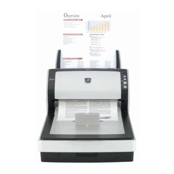
Stacker Scanned documents are ejected from the ADF onto this stacker. Stacker extension Flatbed (FB) [fi-6240/fi-6230 only] Place documents on the glass sheet by sheet for single-sheet scanning. Transport lock switch Used to lock the carrier unit inside the flatbed during transportation. - Page 14 Section 1-1-4 [Rear] fi-6140/fi-6130 fi-6240/fi-6230 Parts name Function Security sot Attaches the antitheft chain EXT connector (for imprinter) Connects the cable from the Imprinter. [fi-6140/fi-6130 only] SCSI connector Connects the SCSI interface cable from the host system. SCSI ID switch Sets the SCSI ID.
- Page 15 Launches the linked application software. Resets and error. Cancels ongoing scanning. Power button / LED Turns the scanner ON and OFF. Lights when the scanner is turned ON. fi-6140/fi-6240/fi-6130/fi-6230/fi-614PR TITLE Maintenance Manual July 27, 09 K.Okada A.Miyoshi I.Fujioka Refer to Revision Record on page 2.
-
Page 16: Outer Dimensions
1-1-5 1-1-5 Outer Dimensions fi-6140/fi-6130 fi-6240/fi-6230 (Unit: mm) fi-6140/fi-6240/fi-6130/fi-6230/fi-614PR TITLE Maintenance Manual July 27, 09 K.Okada A.Miyoshi I.Fujioka Refer to Revision Record on page 2. Nov.12, 08 K.Okada T.Anzai I.Fujioka Refer to Revision Record on page 2. DRAW CUST. -
Page 17: Document Specifications
- The Brake roller or Pick rollers of the scanner could be damaged if photographs or sheets of paper attached to the scanned document have contact with the Brake or Pick rollers during scanning. - Scanning documents of calendered paper such as photographs may damage the surface of them. fi-6140/fi-6240/fi-6130/fi-6230/fi-614PR TITLE Maintenance Manual July 27, 09 K.Okada... -
Page 18: Multi Feed Detection Condition
When the overlapping check is specified, the papers which contact closely each other, such as glued paper or electro-statically charged paper, can result in the miss-detection of multi feed. Multifeed detection monitoring area fi-6140/fi-6240/fi-6130/fi-6230/fi-614PR TITLE Maintenance Manual July 27, 09 K.Okada... -
Page 19: Scanner Configuration
The motor drive circuit and motor fuse are located in the Control PCA. If abnormal electric current runs through the motor drive circuit, the current is cut off by the motor fuse in the Control PCA. fi-6140/fi-6240/fi-6130/fi-6230/fi-614PR TITLE Maintenance Manual July 27, 09 K.Okada... -
Page 20: Reading Station
An image on a document is projected to a color CCD through lens and mirror system and converted to signals with 10 bit per pixel at 600 dpi resolution. (2) FB optical system fi-6240/fi-6230 When FB scanning is specified, a document set on the document bed (glass) is scanned by the Optical Unit of the Carrier unit, which moves in the direction of sub scanning. - Page 21 The scanner terminates scan operation when the length specified from the host is scanned (Fixed size scanning) or when the TOP sensor detects the trailing edge of a document (Page end detection scanning). fi-6140/fi-6240/fi-6130/fi-6230/fi-614PR TITLE Maintenance Manual July 27, 09 K.Okada...
-
Page 22: Controller
Controller Controller PICK Motor Micro Processor Motor ADF Motor SCSI * Driver BW Motor *only fi-6140 has SCSI. fi-6140/fi-6240/fi-6130/fi-6230/fi-614PR TITLE Maintenance Manual July 27, 09 K.Okada A.Miyoshi I.Fujioka Refer to Revision Record on page 2. Nov.12, 08 K.Okada T.Anzai I.Fujioka Refer to Revision Record on page 2. - Page 23 ■ Values of Brake roller counter and Pick roller counter ■ First date of the scanner operation, ADF scanned number of documents (3) Joint PCA fi-6240/fi-6230 This is a PCA installed in carrier unit (a unit including Optical Unit, Lamp, Lamp Inverter) of flatbed and used to convert the connector interface among CR Cable, the cable from Optical Unit and Lamp Inverter.
-
Page 24: Electric Component Block Diagram
Section 1-2-4 1-2-4 Electric Component Block Diagram fi-6140/fi-6240/fi-6130/fi-6230/fi-614PR TITLE Maintenance Manual July 27, 09 K.Okada A.Miyoshi I.Fujioka Refer to Revision Record on page 2. Nov.12, 08 K.Okada T.Anzai I.Fujioka Refer to Revision Record on page 2. DRAW CUST. P1PA03540-B0XX/6 Mar.10, 08 K.Okada T.Anzai... -
Page 25: Chapter 2 Description Of Scanner Operation
3. Cushion TR 4. Cushion TL 8. ADF Paper Chute 7. Scanner 5. Cushion BR 6. Cushion BL 1. Package Box fi-6140/fi-6240/fi-6130/fi-6230/fi-614PR TITLE Maintenance Manual July 27, 09 K.Okada A.Miyoshi I.Fujioka Refer to Revision Record on page 2. Nov.12, 08 K.Okada T.Anzai... - Page 26 Section 2-1 fi-6240/fi-6230 Items Quantity Package box CD tray (including accessories) Cushion TR Cushion TL Cushion BR Cushion BL Scanner in Polyethylene bag ADF paper chute (Chute Unit) and other accessories 2. CD Tray 4. Cushion TL 3. Cushion TR 8.
-
Page 27: Installing The Scanner
(1) fi-6140/fi-6130 If you wish to install the imprinter (optional), refer to Section 8-3-2 before performing the following procedures. (2) fi-6240/fi-6230 Unlock the Transport lock. The carrier unit inside the fi-6240/fi-6230 is fixed in place with the transport lock to prevent the scanner from being damaged during transportation. To unlock the transport lock, slide the transport lock switch on the scanner front. - Page 28 Section 2-2-2 (7) Connect either with the USB cable or the SCSI cable. (fi-6130/fi-6230 has USB cable only.) Note 1: Connect only one of the USB or SCSI cable. Note 2: Be sure to use the USB cable which comes as an accessory with this scanner. Scanning operation with commercially available cables is not guaranteed.
-
Page 29: Chapter 3 Maintenance Parts
Chapter 3 Chapter 3 Maintenance Parts Ref. for Ref. for Quantity Description Part Number Remarks appear- replace- fi-6140 fi-6240 fi-6130 fi-6230 ance ment ADF Section BASE UNIT PA03540-D941 5-9-1 BASE UNIT L PA03540-D951 BASE ASSY PA03540-E941 5-9-2 BASE ASSY L PA03540-E951... - Page 30 Chapter 3 Maintenance Parts (Cont’d) Ref. for Ref. for Quantity Description Part Number Remarks appear- replace- fi-6140 fi-6240 fi-6130 fi-6230 ance ment PA03540-K901 CONTROL PCA PA03540-K917 3-23 5-11 PA03540-K918 CONTROL PCA L PA03540-K919 STACKER UNIT PA03540-E904 3-25 5-8-2 CHUTER UNIT...
-
Page 31: Base Unit
Section 3-1 3-1 BASE UNIT Description Parts No. Remarks BASE UNIT PA03540-D941 fi-6140/fi-6240 BASE UNIT L PA03540-D951 fi-6130/fi-6230 Paper protection sensor 3-2 BASE ASSY Description Parts No. Remarks OPT Unit is not included. BASE ASSY PA03540-E941 fi-6140/fi-6240 (Remove OPT Unit from Base Unit. -
Page 32: Inverter
Parts No. Remarks INVERTER PA03540-K910 3-4 LAMP Description Parts No. Remarks LAMP PA03540-K911 fi-6140/fi-6240/fi-6130/fi-6230/fi-614PR TITLE Maintenance Manual July 27, 09 K.Okada A.Miyoshi I.Fujioka Refer to Revision Record on page 2. Nov.12, 08 K.Okada T.Anzai I.Fujioka Refer to Revision Record on page 2. -
Page 33: Us Sensor Fx (Multifeed Detection)
US shield FX is not included. US Shield FX (not included)) 3-6 OPT UNIT Description Parts No. Remarks OPT UNIT PA03540-E903 fi-6140/fi-6240/fi-6130/fi-6230/fi-614PR TITLE Maintenance Manual July 27, 09 K.Okada A.Miyoshi I.Fujioka Refer to Revision Record on page 2. Nov.12, 08 K.Okada T.Anzai I.Fujioka... -
Page 34: Bw Motor
3-8 GUIDE P ASSY (Sheet Guide) Description Parts No. Remarks GUIDE P ASSY PA03540-E908 fi-6140/fi-6240 GUIDE P ASSY L PA03540-E909 fi-6130/fi-6230 fi-6140/fi-6240/fi-6130/fi-6230/fi-614PR TITLE Maintenance Manual July 27, 09 K.Okada A.Miyoshi I.Fujioka Refer to Revision Record on page 2. Nov.12, 08 K.Okada T.Anzai... -
Page 35: Pick Motor Assy
3-10 PICK MOTOR Description Parts No. Remarks PICK MOTOR PA03540-F903 A belt tension adjusting spring is attached. Adjusting spring fi-6140/fi-6240/fi-6130/fi-6230/fi-614PR TITLE Maintenance Manual July 27, 09 K.Okada A.Miyoshi I.Fujioka Refer to Revision Record on page 2. Nov.12, 08 K.Okada T.Anzai I.Fujioka... -
Page 36: Pick Shaft Assy
PICK SHAFT ASSY PA03540-F907 3-12 SWITCH (ADF open detection) Description Parts No. Remarks SWITCH PA03540-K804 Shared with fi-5120C/fi-5220C. fi-6140/fi-6240/fi-6130/fi-6230/fi-614PR TITLE Maintenance Manual July 27, 09 K.Okada A.Miyoshi I.Fujioka Refer to Revision Record on page 2. Nov.12, 08 K.Okada T.Anzai I.Fujioka Refer to Revision Record on page 2. -
Page 37: Upper Unit
UPPER UNIT L PA03540-D981 fi-6130 for Europe and North America UPPER UNIT LC PA03540-D987 fi-6130 for China UPPER UNIT L PA03540-D991 fi-6230 for Europe and North America UPPER UNIT LC PA03540-D997 fi-6230 for China 3-14 UPPER ASSY Description Parts No. Remarks... -
Page 38: Adf Motor
3-18 (Reserved) 3-19 US SENSOR RV (Multifeed detection) Description Parts No. Remarks US SENSOR RV PA03484-K905 Receiver. Shared with fi-5120C/fi-5220C fi-6140/fi-6240/fi-6130/fi-6230/fi-614PR TITLE Maintenance Manual July 27, 09 K.Okada A.Miyoshi I.Fujioka Refer to Revision Record on page 2. Nov.12, 08 K.Okada T.Anzai I.Fujioka... -
Page 39: Sensor Emp (Paper Empty Detection)
EEPROM data need to be saved. (Refer to Section 6-2.) 3-22 BR SHAFT ASSY Description Parts No. Remarks BR SHAFT ASSY PA03540-F905 fi-6140/fi-6240/fi-6130/fi-6230/fi-614PR TITLE Maintenance Manual July 27, 09 K.Okada A.Miyoshi I.Fujioka Refer to Revision Record on page 2. Nov.12, 08 K.Okada T.Anzai... -
Page 40: Control Pca
Bracket (not included) Bracket (not included) (Back side) These parts do not exist on fi-6140/fi-6130. fi-6140/fi-6130 These parts do not exist on fi-6240/fi-6230. fi-6140/fi-6240/fi-6130/fi-6230/fi-614PR TITLE Maintenance Manual July 27, 09 K.Okada A.Miyoshi I.Fujioka Refer to Revision Record on page 2. -
Page 41: Reserved)
STACKER UNIT PA03540-E904 fi-6140/fi-6130 only 3-26 CHUTER UNIT (ADF paper chute) Description Parts No. Remarks CHUTER UNIT PA03540-E905 fi-6140/fi-6240/fi-6130/fi-6230/fi-614PR TITLE Maintenance Manual July 27, 09 K.Okada A.Miyoshi I.Fujioka Refer to Revision Record on page 2. Nov.12, 08 K.Okada T.Anzai I.Fujioka Refer to Revision Record on page 2. -
Page 42: Ac Adapter
For North America AC CORDSET C PA63084-1831 For China 3-29 USB CABLE Description Parts No. Remarks USB CABLE PA61001-0142 fi-6140/fi-6240/fi-6130/fi-6230/fi-614PR TITLE Maintenance Manual July 27, 09 K.Okada A.Miyoshi I.Fujioka Refer to Revision Record on page 2. Nov.12, 08 K.Okada T.Anzai I.Fujioka Refer to Revision Record on page 2. -
Page 43: Fb Top Cover
3-31 FB MOTOR UNIT Description Parts No. Remarks FB MOTOR UNIT PA03540-E919 A belt tension adjusting spring is attached. Adjusting spring fi-6140/fi-6240/fi-6130/fi-6230/fi-614PR TITLE Maintenance Manual July 27, 09 K.Okada A.Miyoshi I.Fujioka Refer to Revision Record on page 2. Nov.12, 08 K.Okada T.Anzai... -
Page 44: Fb Motor
The following parts are included. - INVERTER - LAMP Core (not included) Inverter cable (not included) 3-34 (Reserved) 3-35 (Reserved) 3-36 (Reserved) fi-6140/fi-6240/fi-6130/fi-6230/fi-614PR TITLE Maintenance Manual July 27, 09 K.Okada A.Miyoshi I.Fujioka Refer to Revision Record on page 2. Nov.12, 08 K.Okada T.Anzai... -
Page 45: Cr Cable
PA70002-0928 Shared with fi-5220C 3-38 DOC COVER ASSY Description Parts No. Remarks DOC COVER ASSY PA03540-E921 Cushion is attached. fi-6140/fi-6240/fi-6130/fi-6230/fi-614PR TITLE Maintenance Manual July 27, 09 K.Okada A.Miyoshi I.Fujioka Refer to Revision Record on page 2. Nov.12, 08 K.Okada T.Anzai I.Fujioka... -
Page 46: Joint Pca
Section 3-39 3-39 JOINT PCA Description Parts No. Remarks JOINT PCA PA03540-K916 6-40 (Reserved) fi-6140/fi-6240/fi-6130/fi-6230/fi-614PR TITLE Maintenance Manual July 27, 09 K.Okada A.Miyoshi I.Fujioka Refer to Revision Record on page 2. Nov.12, 08 K.Okada T.Anzai I.Fujioka Refer to Revision Record on page 2. -
Page 47: Chapter 4 Troubleshooting
The Function No. is incremented by 1 every time the Function button is pressed. After Function No. 9 is displayed, the number changes to “C” and then returns to “0”. Any error at initial processing (self-diagnosis) is displayed on the Operator Panel (Fucntion No. Display). fi-6140/fi-6240/fi-6130/fi-6230/fi-614PR TITLE Maintenance Manual July 27, 09 K.Okada... -
Page 48: Temporary Errors And Alarm Detection Algorithm
If the application “Error Recovery Guide” (step (11) of Section 2.2.2) is installed in the PC, the corresponding error name and error code are displayed on the PC screen when any error or scanner alarm comes up. Detail code fi-6140/fi-6240/fi-6130/fi-6230/fi-614PR TITLE Maintenance Manual July 27, 09 K.Okada... -
Page 49: Troubleshooting
Lamp fuse malfunction 048003 84 “L6: US sensor alarm” 4-3-27 Sensor malfunction 044400 nn “F: ROM sum check alarm” 4-3-28 Driver error 4-3-29 fi-6140/fi-6240/fi-6130/fi-6230/fi-614PR TITLE Maintenance Manual July 27, 09 K.Okada A.Miyoshi I.Fujioka Refer to Revision Record on page 2. Nov.12, 08 K.Okada T.Anzai... -
Page 50: Fi-6140/Fi-6240/Fi-6130/Fi-6230/Fi-614Pr
Post-Imprinter Error (ROM) 048010 B8 No printing / Printed letters are distorted 4-3-38 Print form is dirty 4-3-39 Printing is interrupted in process 4-3-40 fi-6140/fi-6240/fi-6130/fi-6230/fi-614PR TITLE Maintenance Manual July 27, 09 K.Okada A.Miyoshi I.Fujioka Refer to Revision Record on page 2. -
Page 51: Scanner Is Not Turned On (Display Of The Operator Panel Goes Out)
ADF back scanning: See Section 5-10-4 for replacement. FB scanning: See Section 5-12-5 for replacement. Replace Control PCA and see if the error Refer to Section 5-11. is resolved. fi-6140/fi-6240/fi-6130/fi-6230/fi-614PR TITLE Maintenance Manual July 27, 09 K.Okada A.Miyoshi I.Fujioka Refer to Revision Record on page 2. -
Page 52: Resolution Is Not Satisfactory Or Tone Error Is Too Large
Refer to Section 5-11. is resolved. 4-3-5 Too much jitter on scanned image with FB scanning fi-6240/fi-6230 The following shows the sample of scanned image when “Jitter” error occurs. This error occurs when the carrier unit does not move smoothly. -
Page 53: Scanned Image Is Misaligned With Fb Scanning Fi-6240/Fi-6230
Section 4-3-6 4-3-6 Scanned image is misaligned with FB scanning fi-6240/fi-6230 Table 4-3-6 Item Check items How/where to check Check the items listed in the right Any shock given to the scanner during operation? ・ column. ・ Is the scanner placed on a level surface? ・... -
Page 54: Too Much Jitter On Scanned Image With Adf Scanning
Replace Upper Unit and see if the error Refer to Section 5-10-1. is resolved. Replace Base Unit and see if the error is Refer to Section 5-9-1. resolved. fi-6140/fi-6240/fi-6130/fi-6230/fi-614PR TITLE Maintenance Manual July 27, 09 K.Okada A.Miyoshi I.Fujioka Refer to Revision Record on page 2. -
Page 55: Scanned Image Is Misaligned With Adf Scanning
Is the OPT Unit installed correctly? ADF (front) scanning: Refer to Section 5-9-6. ADF (back) scanning: Refer to Section 5-10-4. Replace the OPT Unit and see whether the error is resolved. fi-6140/fi-6240/fi-6130/fi-6230/fi-614PR TITLE Maintenance Manual July 27, 09 K.Okada A.Miyoshi I.Fujioka Refer to Revision Record on page 2. -
Page 56: Vertical Streaks Appear In Scanned Image
Are the white reference and glass in the ADF dirty? ・ Conduct white adjustment Refer to Section 6-1-5. Maintenance mode. fi-6140/fi-6240/fi-6130/fi-6230/fi-614PR TITLE Maintenance Manual July 27, 09 K.Okada A.Miyoshi I.Fujioka Refer to Revision Record on page 2. Nov.12, 08 K.Okada T.Anzai... -
Page 57: Frequent "J1: Paper Jam" Error At Scanner Section
If not operating, then replace Base Unit: Refer to Section 5-9-1. the Base Unit. Replace the Control PCA and see if the Refer to Section 5-11. error is resolved. fi-6140/fi-6240/fi-6130/fi-6230/fi-614PR TITLE Maintenance Manual July 27, 09 K.Okada A.Miyoshi I.Fujioka Refer to Revision Record on page 2. -
Page 58: Frequent "J2: Multi Feed Error
Referring to Section 6-1-2, perform the sensor test. sensor. If the sensor does not operate, check if the sensor cable is correctly connected, then replace the Sensor EMP. (Refer to Section 5-10-8.) fi-6140/fi-6240/fi-6130/fi-6230/fi-614PR TITLE Maintenance Manual July 27, 09 K.Okada A.Miyoshi I.Fujioka... -
Page 59: Frequent "U0: Shipping Lock Error" Or "E0: Carrier Drive Alarm
E2 (ADF front): Refer to Section 5-9-6. E3 (ADF back): Refer to Section 5-10-4. Replace the Control PCA and see if the Refer to Section 5-11. error is resolved. fi-6140/fi-6240/fi-6130/fi-6230/fi-614PR TITLE Maintenance Manual July 27, 09 K.Okada A.Miyoshi I.Fujioka Refer to Revision Record on page 2. -
Page 60: E6: Operator Panel Alarm
OFF, and after more than 2 seconds elapse, press the power button to turn the scanner ON. Replace the Control PCA and see if the Refer to Section 5-11 for replacement. error is resolved. fi-6140/fi-6240/fi-6130/fi-6230/fi-614PR TITLE Maintenance Manual July 27, 09 K.Okada A.Miyoshi I.Fujioka... -
Page 61: F4: Background Changeover Unit Alarm
OFF, and after more than 2 seconds elapse, press the power button to turn the scanner ON. Replace the Control PCA and see if the Refer to Section 5-11 for replacement. error is resolved. fi-6140/fi-6240/fi-6130/fi-6230/fi-614PR TITLE Maintenance Manual July 27, 09 K.Okada A.Miyoshi I.Fujioka... -
Page 62: H0/H8: Motor Alarm
PICK Motor: Refer to Section 5-9-10. FB Motor: Refer to Section 5-12-3. BW Motor: Refer to Section 5-9-7. Replace Control PCA and see if the error Refer to Section 5-11 for replacement. is resolved. fi-6140/fi-6240/fi-6130/fi-6230/fi-614PR TITLE Maintenance Manual July 27, 09 K.Okada A.Miyoshi I.Fujioka Refer to Revision Record on page 2. -
Page 63: Lamp Alarm
Is the connector between the scanner and Refer to Section 2-2-2. the PC correctly connected? Refer to Section 5-11 for replacement. Replace the Control PCA and see if the error is resolved. fi-6140/fi-6240/fi-6130/fi-6230/fi-614PR TITLE Maintenance Manual July 27, 09 K.Okada A.Miyoshi I.Fujioka Refer to Revision Record on page 2. -
Page 64: Abnormal Command
Cover Open sensor installation position. If the sensor does not operate properly, check if the sensor cable is correctly connected. If the sensor is defective, replace the Switch. (Refer to Section 8-6-11 “Switch (Cover open detection).”) fi-6140/fi-6240/fi-6130/fi-6230/fi-614PR TITLE Maintenance Manual July 27, 09 K.Okada A.Miyoshi I.Fujioka... -
Page 65: Imprinter Does Not Initially Operate (With Imprinter Installed) Fi-6140/Fi-6130
IMP JNT (Section 8-6-7) replace them if necessary. Replace the Imprinter Control PCA Refer to Section 8-6-9. (IMP CT) and see if the error is resolved. fi-6140/fi-6240/fi-6130/fi-6230/fi-614PR TITLE Maintenance Manual July 27, 09 K.Okada A.Miyoshi I.Fujioka Refer to Revision Record on page 2. -
Page 66: H6: Imprinter Fuse Blown" (With Imprinter Installed) Fi-6140/Fi-6130
Replace the Imprinter Control PCA Refer to Section 8-6-9. (IMP CT) and see if the error is resolved. Replace the Scanner Control PCA and Refer to Section 5-11. see if the error is resolved. fi-6140/fi-6240/fi-6130/fi-6230/fi-614PR TITLE Maintenance Manual July 27, 09 K.Okada A.Miyoshi I.Fujioka Refer to Revision Record on page 2. -
Page 67: No Printing / Printed Letters Are Distorted (With Imprinter Installed) Fi-6140/Fi-6130
IMP JNT (Section 8-6-9) replace them if necessary. Replace the Imprinter Control PCA Refer to Section 8-6-9. (IMP CT) and see if the error is resolved. fi-6140/fi-6240/fi-6130/fi-6230/fi-614PR TITLE Maintenance Manual July 27, 09 K.Okada A.Miyoshi I.Fujioka Refer to Revision Record on page 2. -
Page 68: Frequent "J0: Paper Jam" (Paper Protection Function) Fi-6140/Fi-6240
If not operating, then replace Base Unit: Refer to Section 5-9-1. the Base Unit. Replace the Control PCA and see if the Refer to Section 5-11. error is resolved. fi-6140/fi-6240/fi-6130/fi-6230/fi-614PR TITLE Maintenance Manual July 27, 09 K.Okada A.Miyoshi I.Fujioka Refer to Revision Record on page 2. -
Page 69: Chapter 5 Disassembly/Assembly
When removing parts that are held in place with hooks, be very careful not to break the hooks. Pull out the latch to unlock, then pull up on the assembly to remove. Do not use excessive force when removing parts held in place with hooks. HOOK fi-6140/fi-6240/fi-6130/fi-6230/fi-614PR TITLE Maintenance Manual July 27, 09 K.Okada A.Miyoshi I.Fujioka... -
Page 70: Periodic Maintenance
Glass inside of Base Unit (Refer to Section 5-3-2) • Glass inside of Upper Unit (Refer to Section 5-3-3) • Glass inside of Flatbed (Refer to Section 5-3-4) fi-6240/fi-6230 • White reference sheet inside of Base Unit (Refer to Section 5-3-5) •... -
Page 71: Cleaning
1. Take care not to damage the Lamp as it is thin. 2. Conduct the procedure under dust-free environment. 3. Do NOT apply external force to the OPT frame, Mirror, Mirror holder and CCD board. fi-6140/fi-6240/fi-6130/fi-6230/fi-614PR TITLE Maintenance Manual July 27, 09 K.Okada... -
Page 72: Glass Inside Of Flatbed Fi-6240/Fi-6230
5-3-4 Glass inside of Flatbed fi-6240/fi-6230 Follow the procedure below to clean the glass inside of the Flatbed. Referring to Section 5-12-7 “Lamp (fi-6240/fi-6230),” remove the Lamp. 1) Referring to Section 5-12-1, remove the FB Top cover. Clean inside of the glass of the OPT BOX Unit FB Top Cover with a cloth moistened with alcohol. Be sure that no fabric from the cloth remains on the glass surface and that the glass is cleaned evenly. -
Page 73: Maintenance Tool
Magnification/Offset Magnification/Offset adjustment Prepare the sheet described in Figure 6-1-3 adjustment sheet (Sections 6-1-3, 6-1-4) (Section 6-1-3 “Maintenance Mode #2”) in advance. fi-6140/fi-6240/fi-6130/fi-6230/fi-614PR TITLE Maintenance Manual July 27, 09 K.Okada A.Miyoshi I.Fujioka Refer to Revision Record on page 2. Nov.12, 08 K.Okada T.Anzai... -
Page 74: Parts That Should Not Be Disassembled
Do not disassemble any screws and any parts (including printed board and mirrors) of the OPT Unit. CCD board fixing screws A (2) CR Belt tension bracket fixing screw fi-6240/fi-6230 If you have accidentally loosened this screw, adjust the belt tension referring to <Installation> of Section 5-12-2 “FB Motor Unit.”... -
Page 75: Removing Flatbed Fi-6240/Fi-6230
Section 5-7 5-7 Removing Flatbed fi-6240/fi-6230 - Refer to Appendix for the specification of the screws. <Removal> 1. Remove Flatbed. (1) - Place the scanner at the edge of a table as shown in the lower right photo. - Remove two screws C (circles below) at the bottom of the Flatbed. -
Page 76: Fi-6140/Fi-6240/Fi-6130/Fi-6230/Fi-614Pr
Note: Bury the CR cable and FB Motor cable in the hole. Do NOT pinch these cables between ADF and Flatbed sections. Note: Make sure that there is no gap between the ADF and Flatbed sections. fi-6140/fi-6240/fi-6130/fi-6230/fi-614PR TITLE Maintenance Manual July 27, 09 K.Okada... -
Page 77: Chuter Unit (Adf Paper Chute), Stacker Unit
Hold the Chuter Unit (ADF paper chute) and insert its tabs into the corresponding slots in the scanner as shown below. The side guides of the Chuter Unit (ADF paper chute) have to face up. Chuter Unit (ADF paper chute) Side guide fi-6140/fi-6240/fi-6130/fi-6230/fi-614PR TITLE Maintenance Manual July 27, 09 K.Okada A.Miyoshi I.Fujioka... -
Page 78: Stacker Unit Fi-6140/Fi-6130
(1) Bending the center (square below) of the Stacker Unit slightly, remove one pin (circle below) of the Stacker Unit and another, and then remove the Stacker Unit. <Installation> Follow the above procedure in reverse. fi-6140/fi-6240/fi-6130/fi-6230/fi-614PR TITLE Maintenance Manual July 27, 09 K.Okada... -
Page 79: Base Unit
Imprinter Referring to Section 8-6-4 “Removing Imprinter”, remove the Imprinter. Remove Flatbed. fi-6240/fi-6230 Referring to Section 5-7 “Removing Flatbed”, remove the Flatbed. 1. Remove Chuter Unit. (1) Referring to Section 5-8-1 “Chuter Unit (ADF Paper Chute)”, remove the Chuter Unit. -
Page 80: Fi-6140/Fi-6240/Fi-6130/Fi-6230/Fi-614Pr
Section 5-9-1 (5) - Open the Upper Unit. - Push two claws (circles below) with a flat-blade screwdriver outward to unlatch. Base Unit Cover Base Unit Upper Unit fi-6140/fi-6240/fi-6130/fi-6230/fi-614PR TITLE Maintenance Manual July 27, 09 K.Okada A.Miyoshi I.Fujioka Refer to Revision Record on page 2. -
Page 81: Fi-6140/Fi-6240/Fi-6130/Fi-6230/Fi-614Pr
Unit. - Tilt the flat-blade screwdriver inward to unlatch the fulcrum pin, and then separate the Upper Unit and Base Unit. Base Unit Upper Unit Base Unit Upper Unit fi-6140/fi-6240/fi-6130/fi-6230/fi-614PR TITLE Maintenance Manual July 27, 09 K.Okada A.Miyoshi I.Fujioka Refer to Revision Record on page 2. -
Page 82: Fi-6140/Fi-6240/Fi-6130/Fi-6230/Fi-614Pr
Wire the BS HARNES, SE HARNESS and ADF MOTOR HARNESS from the shield plate holes (circles below). Be careful not to tuck down the cable when installing the Base unit Cover LID. Base unit cover LID fi-6140/fi-6240/fi-6130/fi-6230/fi-614PR TITLE Maintenance Manual July 27, 09 K.Okada... -
Page 83: Fi-6140/Fi-6240/Fi-6130/Fi-6230/Fi-614Pr
- Referring to Section 6-1-3 “Maintenance Mode #2,” adjust the magnification. - Referring to Section 6-1-4 “Maintenance Mode #3,” adjust the offset. - Referring to Section 6-1-5 “Maintenance Mode #4,” adjust the white level. Note: Clean the glass surface after replacing the part. fi-6140/fi-6240/fi-6130/fi-6230/fi-614PR TITLE Maintenance Manual July 27, 09 K.Okada... -
Page 84: Base Assy
Imprinter Referring to Section 8-6-4 “Removing Imprinter”, remove the Imprinter. Remove Flatbed. fi-6240/fi-6230 Referring to Section 5-7 “Removing Flatbed,” remove the Flatbed. 1. Remove Chuter Unit. (1) Referring to Section 5-8-1 “Chuter Unit (ADF Paper Chute),” remove the Chuter Unit. -
Page 85: Inverter (For Front Side Scanning)
Imprinter Referring to Section 8-6-4 “Removing Imprinter”, remove the Imprinter. Remove Flatbed. fi-6240/fi-6230 Referring to Section 5-7 “Removing Flatbed,” remove the Flatbed. 1. Remove Chuter Unit. (1) Referring to Section 5-8-1 “Chuter Unit (ADF Paper Chute),” remove the Chuter Unit. -
Page 86: Fi-6140/Fi-6240/Fi-6130/Fi-6230/Fi-614Pr
- Referring to Section 6-1-3 “Maintenance Mode #2,” adjust the magnification. - Referring to Section 6-1-4 “Maintenance Mode #3,” adjust the offset. - Referring to Section 6-1-5 “Maintenance Mode #4,” adjust the white level. fi-6140/fi-6240/fi-6130/fi-6230/fi-614PR TITLE Maintenance Manual July 27, 09 K.Okada... -
Page 87: Lamp (For Front Side Scanning)
Imprinter Referring to Section 8-6-4 “Removing Imprinter”, remove the Imprinter. Remove Flatbed. fi-6240/fi-6230 Referring to Section 5-7 “Removing Flatbed,” remove the Flatbed. 1. Remove Chuter Unit. (1) Referring to Section 5-8-1 “Chuter Unit (ADF Paper Chute),” remove the Chuter Unit. -
Page 88: Fi-6140/Fi-6240/Fi-6130/Fi-6230/Fi-614Pr
- Unhook the lamp cable from the Inverter (circle below), and then remove the Lamp. 3 Reflector Inverter Lamp Lamp cable Thin lamp cable Frame groove fi-6140/fi-6240/fi-6130/fi-6230/fi-614PR TITLE Maintenance Manual July 27, 09 K.Okada A.Miyoshi I.Fujioka Refer to Revision Record on page 2. -
Page 89: Fi-6140/Fi-6240/Fi-6130/Fi-6230/Fi-614Pr
Thin Lamp cable (2) Install the reflector to the frame. Note: Make sure that the protrusions of the reflector are inserted into the holes of the frame. Reflector Frame holes Protrusions fi-6140/fi-6240/fi-6130/fi-6230/fi-614PR TITLE Maintenance Manual July 27, 09 K.Okada A.Miyoshi I.Fujioka Refer to Revision Record on page 2. -
Page 90: Fi-6140/Fi-6240/Fi-6130/Fi-6230/Fi-614Pr
Section 5-9-4 (3) Install the BK Cover to the frame. Note: Make sure that seven claws are secured. BK Cover fi-6140/fi-6240/fi-6130/fi-6230/fi-614PR TITLE Maintenance Manual July 27, 09 K.Okada A.Miyoshi I.Fujioka Refer to Revision Record on page 2. Nov.12, 08 K.Okada T.Anzai... -
Page 91: Fi-6140/Fi-6240/Fi-6130/Fi-6230/Fi-614Pr
Section 5-9-4 (4) Connect the Lamp cable to the Inverter (circle below). Inverter Lamp Cable fi-6140/fi-6240/fi-6130/fi-6230/fi-614PR TITLE Maintenance Manual July 27, 09 K.Okada A.Miyoshi I.Fujioka Refer to Revision Record on page 2. Nov.12, 08 K.Okada T.Anzai I.Fujioka Refer to Revision Record on page 2. -
Page 92: Fi-6140/Fi-6240/Fi-6130/Fi-6230/Fi-614Pr
- Referring to Section 6-1-3 “Maintenance Mode #2,” adjust the magnification. - Referring to Section 6-1-4 “Maintenance Mode #3,” adjust the offset. - Referring to Section 6-1-5 “Maintenance Mode #4,” adjust the white level. fi-6140/fi-6240/fi-6130/fi-6230/fi-614PR TITLE Maintenance Manual July 27, 09 K.Okada... -
Page 93: Us Sensor Fx (Multifeed Detection)
Imprinter Referring to Section 8-6-4 “Removing Imprinter”, remove the Imprinter. Remove Flatbed. fi-6240/fi-6230 Referring to Section 5-7 “Removing Flatbed,” remove the Flatbed. 1. Remove Chuter Unit. (1) Referring to Section 5-8-1 “Chuter Unit (ADF Paper Chute),” remove the Chuter Unit. -
Page 94: Fi-6140/Fi-6240/Fi-6130/Fi-6230/Fi-614Pr
Blow out the dust inside of the Glass and the OPT Unit with air before installation. Wire the US Sensor FX cable as shown below. Nylon band US sensor FX connector fi-6140/fi-6240/fi-6130/fi-6230/fi-614PR TITLE Maintenance Manual July 27, 09 K.Okada A.Miyoshi I.Fujioka Refer to Revision Record on page 2. -
Page 95: Fi-6140/Fi-6240/Fi-6130/Fi-6230/Fi-614Pr
- Referring to Section 6-1-3 “Maintenance Mode #2,” adjust the magnification. - Referring to Section 6-1-4 “Maintenance Mode #3,” adjust the offset. - Referring to Section 6-1-5 “Maintenance Mode #4,” adjust the white level. fi-6140/fi-6240/fi-6130/fi-6230/fi-614PR TITLE Maintenance Manual July 27, 09 K.Okada... -
Page 96: Opt Unit (For Front Side Scanning)
Imprinter Referring to Section 8-6-4 “Removing Imprinter”, remove the Imprinter. Remove Flatbed. fi-6240/fi-6230 Referring to Section 5-7 “Removing Flatbed,” remove the Flatbed. 1. Remove Chuter Unit. (1) Referring to Section 5-8-1 “Chuter Unit (ADF Paper Chute),” remove the Chuter Unit. -
Page 97: Fi-6140/Fi-6240/Fi-6130/Fi-6230/Fi-614Pr
- Referring to Section 6-1-3 “Maintenance Mode #2,” adjust the magnification. - Referring to Section 6-1-4 “Maintenance Mode #3,” adjust the offset. - Referring to Section 6-1-5 “Maintenance Mode #4,” adjust the white level. fi-6140/fi-6240/fi-6130/fi-6230/fi-614PR TITLE Maintenance Manual July 27, 09 K.Okada... -
Page 98: Bw Motor
Imprinter Referring to Section 8-6-4 “Removing Imprinter”, remove the Imprinter. Remove Flatbed. fi-6240/fi-6230 Referring to Section 5-7 “Removing Flatbed,” remove the Flatbed. 1. Remove Chuter Unit. (1) Referring to Section 5-8-1 “Chuter Unit (ADF Paper Chute),” remove the Chuter Unit. -
Page 99: Fi-6140/Fi-6240/Fi-6130/Fi-6230/Fi-614Pr
- Referring to Section 6-1-3 “Maintenance Mode #2,” adjust the magnification. - Referring to Section 6-1-4 “Maintenance Mode #3,” adjust the offset. - Referring to Section 6-1-5 “Maintenance Mode #4,” adjust the white level. fi-6140/fi-6240/fi-6130/fi-6230/fi-614PR TITLE Maintenance Manual July 27, 09 K.Okada... -
Page 100: Guide P Assy (Sheet Guide)
Upper Unit Base Unit Paper protection roller Guide P ASSY Guide P ASSY <Installation> Follow the removing procedure in reverse. fi-6140/fi-6240/fi-6130/fi-6230/fi-614PR TITLE Maintenance Manual July 27, 09 K.Okada A.Miyoshi I.Fujioka Refer to Revision Record on page 2. Nov.12, 08 K.Okada T.Anzai... -
Page 101: Pick Motor Assy
Imprinter Referring to Section 8-6-4 “Removing Imprinter”, remove the Imprinter. Remove Flatbed. fi-6240/fi-6230 Referring to Section 5-7 “Removing Flatbed,” remove the Flatbed. 1. Remove Chuter Unit. (1) Referring to Section 5-8-1 “Chuter Unit (ADF Paper Chute),” remove the Chuter Unit. -
Page 102: Fi-6140/Fi-6240/Fi-6130/Fi-6230/Fi-614Pr
Note: To confirm that the Pick Motor ASSY falls into the positioning boss, make sure that the centers of the gear pulleys come to the center of the frame. Centers of Gear Pulleys Screws C PICK Motor ASSY fi-6140/fi-6240/fi-6130/fi-6230/fi-614PR TITLE Maintenance Manual July 27, 09 K.Okada A.Miyoshi I.Fujioka... -
Page 103: Pick Motor
Imprinter Referring to Section 8-6-4 “Removing Imprinter”, remove the Imprinter. Remove Flatbed. fi-6240/fi-6230 Referring to Section 5-7 “Removing Flatbed,” remove the Flatbed. 1. Remove Chuter Unit. (1) Referring to Section 5-8-1 “Chuter Unit (ADF Paper Chute),” remove the Chuter Unit. -
Page 104: Fi-6140/Fi-6240/Fi-6130/Fi-6230/Fi-614Pr
Adjusting spring PICK Motor P ASSY Hook PICK Motor (2) Check the belt tension. F = 500g ± 150g Spring balance fi-6140/fi-6240/fi-6130/fi-6230/fi-614PR TITLE Maintenance Manual July 27, 09 K.Okada A.Miyoshi I.Fujioka Refer to Revision Record on page 2. Nov.12, 08 K.Okada T.Anzai... -
Page 105: Pick Shaft Assy
(2) Remove the Pick roller from the shaft while lifting up the tab on the Pick roller. PICK Shaft ASSY Shaft Pick roller Pick roller <Installation> Follow the above procedure in reverse. fi-6140/fi-6240/fi-6130/fi-6230/fi-614PR TITLE Maintenance Manual July 27, 09 K.Okada A.Miyoshi I.Fujioka Refer to Revision Record on page 2. -
Page 106: Switch (Adf Open Detection)
Imprinter Referring to Section 8-6-4 “Removing Imprinter”, remove the Imprinter. Remove Flatbed. fi-6240/fi-6230 Referring to Section 5-7 “Removing Flatbed,” remove the Flatbed. 1. Remove Chuter Unit. (1) Referring to Section 5-8-1 “Chuter Unit (ADF Paper Chute),” remove the Chuter Unit. -
Page 107: Upper Unit
Imprinter Referring to Section 8-6-4 “Removing Imprinter”, remove the Imprinter. Remove Flatbed. fi-6240/fi-6230 Referring to Section 5-7 “Removing Flatbed,” remove the Flatbed. 1. Remove Chuter Unit. (1) Referring to Section 5-8-1 “Chuter Unit (ADF Paper Chute),” remove the Chuter Unit. -
Page 108: Upper Assy
Imprinter Referring to Section 8-6-4 “Removing Imprinter”, remove the Imprinter. Remove Flatbed. fi-6240/fi-6230 Referring to Section 5-7 “Removing Flatbed,” remove the Flatbed. 1. Remove Chuter Unit. (1) Referring to Section 5-8-1 “Chuter Unit (ADF Paper Chute),” remove the Chuter Unit. -
Page 109: Adf Motor
(6) Remove the ADF Motor cable from the frame hole at the bottom of the ADF. 02 (7) Open the Upper Unit. 02 (8) Unfasten the screw C (square below) of the belt tension bracket, and then remove the ADF Motor Belt. 02 fi-6140/fi-6240/fi-6130/fi-6230/fi-614PR TITLE Maintenance Manual July 27, 09 K.Okada... -
Page 110: Fi-6140/Fi-6240/Fi-6130/Fi-6230/Fi-614Pr
Note: When the left pulley is 90 degrees, the right pulley must be 45 ± 25 degrees. 25deg 25deg 25deg 25deg 90deg 45deg fi-6140/fi-6240/fi-6130/fi-6230/fi-614PR TITLE Maintenance Manual July 27, 09 K.Okada A.Miyoshi I.Fujioka Refer to Revision Record on page 2. -
Page 111: Fi-6140/Fi-6240/Fi-6130/Fi-6230/Fi-614Pr
- Referring to Section 6-1-3 “Maintenance Mode #2,” adjust the magnification. - Referring to Section 6-1-4 “Maintenance Mode #3,” adjust the offset. - Referring to Section 6-1-5 “Maintenance Mode #4,” adjust the white level. Note: Clean the glass surface after replacing the part. fi-6140/fi-6240/fi-6130/fi-6230/fi-614PR TITLE Maintenance Manual July 27, 09 K.Okada... -
Page 112: Opt Unit (For Backside Scanning)
Note: Pinching the root of connector of the CCD board to support, pull out the CCD cable straight. - Remove the screw A (circle below) on the OPT Hold Plate, and then remove the OPT Hold Plate. 2 - Lift up the OPT Unit 3 to remove. OPT Unit fi-6140/fi-6240/fi-6130/fi-6230/fi-614PR TITLE Maintenance Manual July 27, 09 K.Okada... -
Page 113: Fi-6140/Fi-6240/Fi-6130/Fi-6230/Fi-614Pr
- Referring to Section 6-1-3 “Maintenance Mode #2,” adjust the magnification. - Referring to Section 6-1-4 “Maintenance Mode #3,” adjust the offset. - Referring to Section 6-1-5 “Maintenance Mode #4,” adjust the white level. fi-6140/fi-6240/fi-6130/fi-6230/fi-614PR TITLE Maintenance Manual July 27, 09 K.Okada... -
Page 114: Inverter (For Backside Scanning)
(3) Referring to steps (3) ~ (5) of Section 5-10-11 “Top Cover,” remove the Top Cover. 4. Remove Inverter. (4) - Remove two Inverter cables (circles below). - Unlatch two claws (squares below) at both sides of the Inverter to remove the Inverter. Inverter fi-6140/fi-6240/fi-6130/fi-6230/fi-614PR TITLE Maintenance Manual July 27, 09 K.Okada A.Miyoshi I.Fujioka... -
Page 115: Fi-6140/Fi-6240/Fi-6130/Fi-6230/Fi-614Pr
- Referring to Section 6-1-3 “Maintenance Mode #2,” adjust the magnification. - Referring to Section 6-1-4 “Maintenance Mode #3,” adjust the offset. - Referring to Section 6-1-5 “Maintenance Mode #4,” adjust the white level. fi-6140/fi-6240/fi-6130/fi-6230/fi-614PR TITLE Maintenance Manual July 27, 09 K.Okada... -
Page 116: Lamp (For Backside Scanning)
(5) - Remove the thin Lamp cable from six BK Cover hooks (circles below). - Disconnect the Lamp cable from the Inverter (square below). Thin Lamp cable Thick Lamp cable BK Cover fi-6140/fi-6240/fi-6130/fi-6230/fi-614PR TITLE Maintenance Manual July 27, 09 K.Okada A.Miyoshi I.Fujioka... -
Page 117: Fi-6140/Fi-6240/Fi-6130/Fi-6230/Fi-614Pr
Section 5-10-6 (6) Unlatch seven hooks (circles below) on the BK Cover, and then remove the BK Cover in the order of 1 BK cover fi-6140/fi-6240/fi-6130/fi-6230/fi-614PR TITLE Maintenance Manual July 27, 09 K.Okada A.Miyoshi I.Fujioka Refer to Revision Record on page 2. -
Page 118: Fi-6140/Fi-6240/Fi-6130/Fi-6230/Fi-614Pr
(7) - Lift up the reflector to remove. 1 - Remove the Lamp from the thick Lamp cable side at first. 2 Removed on step (5) Reflector Lamp fi-6140/fi-6240/fi-6130/fi-6230/fi-614PR TITLE Maintenance Manual July 27, 09 K.Okada A.Miyoshi I.Fujioka Refer to Revision Record on page 2. -
Page 119: Fi-6140/Fi-6240/Fi-6130/Fi-6230/Fi-614Pr
Thick Lamp cable side (2) Install the reflector to the frame. Note: Make sure that the protrusions of the reflector are inserted into the holes of the frame. Reflector Protrusions Frame hole fi-6140/fi-6240/fi-6130/fi-6230/fi-614PR TITLE Maintenance Manual July 27, 09 K.Okada A.Miyoshi I.Fujioka Refer to Revision Record on page 2. -
Page 120: Fi-6140/Fi-6240/Fi-6130/Fi-6230/Fi-614Pr
Section 5-10-6 (3) Install the BK Cover to the frame. Note: Make sure that seven claws of the frame are secured. BK Cover fi-6140/fi-6240/fi-6130/fi-6230/fi-614PR TITLE Maintenance Manual July 27, 09 K.Okada A.Miyoshi I.Fujioka Refer to Revision Record on page 2. -
Page 121: Fi-6140/Fi-6240/Fi-6130/Fi-6230/Fi-614Pr
(4) - Hook the thin Lamp cable onto six BK Cover hooks (circles below). - Connect the Lamp cable to the Inverter. BK Cover hooks インバータ Thin Lamp cable Thick Lamp cable fi-6140/fi-6240/fi-6130/fi-6230/fi-614PR TITLE Maintenance Manual July 27, 09 K.Okada A.Miyoshi I.Fujioka Refer to Revision Record on page 2. -
Page 122: Fi-6140/Fi-6240/Fi-6130/Fi-6230/Fi-614Pr
- Referring to Section 6-1-3 “Maintenance Mode #2,” adjust the magnification. - Referring to Section 6-1-4 “Maintenance Mode #3,” adjust the offset. - Referring to Section 6-1-5 “Maintenance Mode #4,” adjust the white level. fi-6140/fi-6240/fi-6130/fi-6230/fi-614PR TITLE Maintenance Manual July 27, 09 K.Okada... -
Page 123: Us Sensor Rv (Multifeed Detection)
- Remove US Sensor RV cable (circle below). US Sensor RV <Installation> Follow the removing procedure in reverse. Note: Referring to Section 6-1-2 “Maintenance Mode #1,” check the sensor operation. fi-6140/fi-6240/fi-6130/fi-6230/fi-614PR TITLE Maintenance Manual July 27, 09 K.Okada A.Miyoshi I.Fujioka Refer to Revision Record on page 2. -
Page 124: Sensor Emp (Paper Empty Detection)
Follow the removing procedure in reverse. Note: Make sure that the claws at both sides of the Sensor EMP are securely latched. After replacing the part, perform the sensor test by referring to Section 6-1-2 “Maintenance Mode #1.” fi-6140/fi-6240/fi-6130/fi-6230/fi-614PR TITLE Maintenance Manual July 27, 09 K.Okada... -
Page 125: Panel Pca
- From inside of the Upper Unit, push the claw (circle below) of the Operator Panel with a flat-blade screwdriver downward of the scanner to remove. 1 - Remove the Operator Panel in the order of 2 Inside of Upper Unit Operator Panel fi-6140/fi-6240/fi-6130/fi-6230/fi-614PR TITLE Maintenance Manual July 27, 09 K.Okada A.Miyoshi I.Fujioka... -
Page 126: Fi-6140/Fi-6240/Fi-6130/Fi-6230/Fi-614Pr
(2)Remove the Panel PCA, and then disconnect the Panel PCA cable (circle below). Panel PCA <Installation> Follow the removing procedure in reverse. Note: Referring to Section 6-1-8 “EEPROM data restore,” restore the EEPROM data. fi-6140/fi-6240/fi-6130/fi-6230/fi-614PR TITLE Maintenance Manual July 27, 09 K.Okada A.Miyoshi I.Fujioka... -
Page 127: Br Shaft Assy
- Lift up the right side of the Brake roller and remove the right shaft. Then pull the left shaft out of its hole to remove it. (2) Remove the Brake roller from the RB Shaft ASSY. BR Shaft ASSY Brake roller <Installation> Follow the removing procedure in reverse. fi-6140/fi-6240/fi-6130/fi-6230/fi-614PR TITLE Maintenance Manual July 27, 09 K.Okada A.Miyoshi I.Fujioka Refer to Revision Record on page 2. -
Page 128: Top Cover
- Remove two screws A (circles below) at both sides of the Top Cover. Top Cover (4) - Close the Upper Unit. - Unhook three hooks at the lower position of the Top Cover. Top Cover fi-6140/fi-6240/fi-6130/fi-6230/fi-614PR TITLE Maintenance Manual July 27, 09 K.Okada A.Miyoshi I.Fujioka... -
Page 129: Fi-6140/Fi-6240/Fi-6130/Fi-6230/Fi-614Pr
Section 5-10-11 (5) Move the Top Cover upward to remove of the Top Cover. Top Cover <Installation> Follow the removing procedure in reverse. fi-6140/fi-6240/fi-6130/fi-6230/fi-614PR TITLE Maintenance Manual July 27, 09 K.Okada A.Miyoshi I.Fujioka Refer to Revision Record on page 2. -
Page 130: Control Pca
(2) - Place the ADF as shown below. The photo below is fi-6240/fi-6230. fi-6140/fi-6130 does not have a connector at the bottom of the ADF. - Remove four screws C (circles below) at the bottom of the ADF 1, tilt the Control PCA to the front 2, and then remove the Control PCA 3. -
Page 131: Fi-6140/Fi-6240/Fi-6130/Fi-6230/Fi-614Pr
(left). Connector edge Nylon band Nylon band The nylon band locates at left side of the connector edge (left). fi-6140/fi-6240/fi-6130/fi-6230/fi-614PR TITLE Maintenance Manual July 27, 09 K.Okada A.Miyoshi I.Fujioka Refer to Revision Record on page 2. -
Page 132: Fi-6140/Fi-6240/Fi-6130/Fi-6230/Fi-614Pr
ADF. Bottom of ADF Protrusion of bracket Protrusion of bracket Bottom of ADF Protrusion of bracket Protrusion of bracket fi-6140/fi-6240/fi-6130/fi-6230/fi-614PR TITLE Maintenance Manual July 27, 09 K.Okada A.Miyoshi I.Fujioka Refer to Revision Record on page 2. -
Page 133: Flatbed
Section 5-12-1 5-12 Flatbed 5-12-1 FB Top Cover fi-6240/fi-6230 - Refer to Section 3-30 for the part number of the replacement part. - Refer to Appendix for the specification of the screws. <Removal> Remove Flatbed. Referring to Section 5-7 “Removing Flatbed,” remove the Flatbed. -
Page 134: Fb Motor Unit Fi-6240/Fi-6230
Section 5-12-2 5-12-2 FB Motor Unit fi-6240/fi-6230 Refer to Section 3-31 for the part number of the replacement part. - Refer to Appendix for the specification of the screws. <Removal> Remove Flatbed. Referring to Section 5-7 “Removing Flatbed,” remove the Flatbed. -
Page 135: Fi-6140/Fi-6240/Fi-6130/Fi-6230/Fi-614Pr
Section 5-12-2 (4) Unfasten the FB Belt from the FB Motor Unit 1, and then remove the FB Motor Unit. 2 FB Belt FB Motor Unit fi-6140/fi-6240/fi-6130/fi-6230/fi-614PR TITLE Maintenance Manual July 27, 09 K.Okada A.Miyoshi I.Fujioka Refer to Revision Record on page 2. -
Page 136: Fi-6140/Fi-6240/Fi-6130/Fi-6230/Fi-614Pr
(2) - Place the belt tension adjusting spring that is attached to the Maintenance Part as shown below. - Tighten the screw C (circle below). - Remove the belt tension adjusting spring. Adjusting plate Adjusting spring FB Belt Adjusting pulley fi-6140/fi-6240/fi-6130/fi-6230/fi-614PR TITLE Maintenance Manual July 27, 09 K.Okada A.Miyoshi I.Fujioka Refer to Revision Record on page 2. -
Page 137: Fi-6140/Fi-6240/Fi-6130/Fi-6230/Fi-614Pr
- Referring to Section 6-1-3 “Maintenance Mode #2,” adjust the magnification. - Referring to Section 6-1-4 “Maintenance Mode #3,” adjust the offset. - Referring to Section 6-1-5 “Maintenance Mode #4,” adjust the white level. fi-6140/fi-6240/fi-6130/fi-6230/fi-614PR TITLE Maintenance Manual July 27, 09 K.Okada... -
Page 138: Fb Motor Fi-6240/Fi-6230
Section 5-12-3 5-12-3 FB Motor fi-6240/fi-6230 - Refer to Section 3-32 for the part number of the replacement part. - Refer to Appendix for the specification of the screws. <Removal> Remove Flatbed. Referring to Section 5-7 “Removing Flatbed,” remove the Flatbed. -
Page 139: Fi-6140/Fi-6240/Fi-6130/Fi-6230/Fi-614Pr
Balance spring Place the FB Motor as shown below, and screw the FB Motor with its own weight. F = 150gf ~ 400gf fi-6140/fi-6240/fi-6130/fi-6230/fi-614PR TITLE Maintenance Manual July 27, 09 K.Okada A.Miyoshi I.Fujioka Refer to Revision Record on page 2. -
Page 140: Opt Box Unit Fi-6240/Fi-6230
Section 5-12-4 5-12-4 OPT Box Unit fi-6240/fi-6230 - The OPT Unit, Joint PCA, core, and Inverter cable are not included. - The Inverter and Lamp are included. - Re-install the OPT Unit, Joint PCA, core and Inverter cable. - Refer to Section 3-33 for the part number of the replacement part. -
Page 141: Fi-6140/Fi-6240/Fi-6130/Fi-6230/Fi-614Pr
(6) Referring to Step (4) of Section 5-12-10 “Joint PCA,” remove the Joint PCA. 6. Remove the core and Inverter cable. (7) Remove the core and Inverter cable. Core Inverter cable fi-6140/fi-6240/fi-6130/fi-6230/fi-614PR TITLE Maintenance Manual July 27, 09 K.Okada A.Miyoshi I.Fujioka Refer to Revision Record on page 2. -
Page 142: Fi-6140/Fi-6240/Fi-6130/Fi-6230/Fi-614Pr
- Referring to Section 6-1-3 “Maintenance Mode #2,” adjust the magnification. - Referring to Section 6-1-4 “Maintenance Mode #3,” adjust the offset. - Referring to Section 6-1-5 “Maintenance Mode #4,” adjust the white level. fi-6140/fi-6240/fi-6130/fi-6230/fi-614PR TITLE Maintenance Manual July 27, 09 K.Okada... -
Page 143: Opt Unit Fi-6240/Fi-6230
Section 5-12-5 5-12-5 OPT Unit fi-6240/fi-6230 - Refer to Section 3-6 for the part number of the replacement part. - Refer to Appendix for the specification of the screws. <Removal> Remove Flatbed. Referring to Section 5-7 “Removing Flatbed,” remove the Flatbed. -
Page 144: Fi-6140/Fi-6240/Fi-6130/Fi-6230/Fi-614Pr
- Referring to Section 6-1-3 “Maintenance Mode #2,” adjust the magnification. - Referring to Section 6-1-4 “Maintenance Mode #3,” adjust the offset. - Referring to Section 6-1-5 “Maintenance Mode #4,” adjust the white level. fi-6140/fi-6240/fi-6130/fi-6230/fi-614PR TITLE Maintenance Manual July 27, 09 K.Okada... -
Page 145: Inverter Fi-6240/Fi-6230
Section 5-12-6 5-12-6 Inverter fi-6240/fi-6230 Refer to Section 3-3 for the part number of the replacement part. <Removal> Remove Flatbed. Referring to Section 5-7 “Removing Flatbed,” remove the Flatbed. 1. Remove Document Cover. (1) Referring to Section 5-12-9 “Document Cover,” remove the Document Cover. -
Page 146: Fi-6140/Fi-6240/Fi-6130/Fi-6230/Fi-614Pr
- Referring to Section 6-1-3 “Maintenance Mode #2,” adjust the magnification. - Referring to Section 6-1-4 “Maintenance Mode #3,” adjust the offset. - Referring to Section 6-1-5 “Maintenance Mode #4,” adjust the white level. fi-6140/fi-6240/fi-6130/fi-6230/fi-614PR TITLE Maintenance Manual July 27, 09 K.Okada... -
Page 147: Lamp Fi-6240/Fi-6230
Section 5-12-7 5-12-7 Lamp fi-6240/fi-6230 Refer to Section 3-4 for the part number of the replacement part. - Refer to Appendix for the specification of the screws. <Removal> Remove Flatbed. Referring to Section 5-7 “Removing Flatbed,” remove the Flatbed. 1. Remove Document Cover. -
Page 148: Fi-6140/Fi-6240/Fi-6130/Fi-6230/Fi-614Pr
- Remove the Lamp. Removed on step (4) Lamp cable Removed on step (4) Thin Lamp cable Frame groove Lamp fi-6140/fi-6240/fi-6130/fi-6230/fi-614PR TITLE Maintenance Manual July 27, 09 K.Okada A.Miyoshi I.Fujioka Refer to Revision Record on page 2. Nov.12, 08 K.Okada T.Anzai... -
Page 149: Fi-6140/Fi-6240/Fi-6130/Fi-6230/Fi-614Pr
- Referring to Section 6-1-3 “Maintenance Mode #2,” adjust the magnification. - Referring to Section 6-1-4 “Maintenance Mode #3,” adjust the offset. - Referring to Section 6-1-5 “Maintenance Mode #4,” adjust the white level. fi-6140/fi-6240/fi-6130/fi-6230/fi-614PR TITLE Maintenance Manual July 27, 09 K.Okada... -
Page 150: Cr Cable Fi-6240/Fi-6230
Section 5-12-8 5-12-8 CR Cable fi-6240/fi-6230 Refer to Section 3-37 for the part number of the replacement part. <Removal> Remove Flatbed. Referring to Section 5-7 “Removing Flatbed,” remove the Flatbed. 1. Remove Document Cover. (1) Referring to Section 5-12-9 “Document Cover,” remove the Document Cover. -
Page 151: Fi-6140/Fi-6240/Fi-6130/Fi-6230/Fi-614Pr
Section 5-12-8 (4) - Unhook the CR Sheet from two claws (squares below) of the frame.1 - Unhook the CR Cable from two claws (squares below) of the frame.2 CR cable CR sheet fi-6140/fi-6240/fi-6130/fi-6230/fi-614PR TITLE Maintenance Manual July 27, 09 K.Okada A.Miyoshi I.Fujioka... -
Page 152: Fi-6140/Fi-6240/Fi-6130/Fi-6230/Fi-614Pr
Note: With white face of the CR Cable down, lead the shorter bent side under the hook of the frame. Lead the shorter bent side of the CR Cable through. Note: Lead the shorter bent side under the hook of the frame. fi-6140/fi-6240/fi-6130/fi-6230/fi-614PR TITLE Maintenance Manual July 27, 09 K.Okada... -
Page 153: Document Cover Fi-6240/Fi-6230
Section 5-12-9 5-12-9 Document Cover fi-6240/fi-6230 Refer to Section 3-38 for the part number of the replacement part. <Removal> 1. Remove Document Cover. (1) Open the Document Cover, and then lift it up. Document Cover <Installation> Follow the removing procedure in reverse. -
Page 154: Joint Pca Fi-6240/Fi-6230
Section 5-12-10 5-12-10 Joint PCA fi-6240/fi-6230 Refer to Section 3-39 for the part number of the replacement part. - Refer to Appendix for the specification of the screws. <Removal> Remove Flatbed. Referring to Section 5-7 “Removing Flatbed,” remove the Flatbed. -
Page 155: Fi-6140/Fi-6240/Fi-6130/Fi-6230/Fi-614Pr
- Referring to Section 6-1-3 “Maintenance Mode #2,” adjust the magnification. - Referring to Section 6-1-4 “Maintenance Mode #3,” adjust the offset. - Referring to Section 6-1-5 “Maintenance Mode #4,” adjust the white level. fi-6140/fi-6240/fi-6130/fi-6230/fi-614PR TITLE Maintenance Manual July 27, 09 K.Okada... -
Page 156: Chapter 6 Adjustment/Settings
Mode 2: Main scanning/Sub-scanning magnification adjustment Mode 3: Offset adjustment Mode 4: White level adjustment Mode 5: Consumables counter display and reset Mode 6: Miscellaneous information display Mode 7: EEPROM data restore fi-6140/fi-6240/fi-6130/fi-6230/fi-614PR TITLE Maintenance Manual July 27, 09 K.Okada A.Miyoshi I.Fujioka Refer to Revision Record on page 2. -
Page 157: Fi-6140/Fi-6240/Fi-6130/Fi-6230/Fi-614Pr
6-1-8 (Reserved) * Pressing the Function button returns to #1. (4) Starting the Maintenance mode Select one Maintenance mode and press Scan. The scanner activates the selected Maintenance mode. fi-6140/fi-6240/fi-6130/fi-6230/fi-614PR TITLE Maintenance Manual July 27, 09 K.Okada A.Miyoshi I.Fujioka Refer to Revision Record on page 2. -
Page 158: Maintenance Mode #1: Paper Feeding / Sensor / Background Changeover Test
4 or 6. A total of 39 characters are printed in pattern 2 or 5. Printing is repeated in the order of pattern 1 3… The numbering data portion is incremented by one from “00000000.” fi-6140/fi-6240/fi-6130/fi-6230/fi-614PR TITLE Maintenance Manual July 27, 09 K.Okada... -
Page 159: Fi-6140/Fi-6240/Fi-6130/Fi-6230/Fi-614Pr
(5) Press the Scan/Stop button. The ADF operation is started if there is any paper on the ADF paper chute (Chuter unit) (Sensor EMP: ON). In case of fi-6240/fi-6230, FB operation is started if there is no paper on the ADF paper chute (Chuter unit). -
Page 160: Maintenance Mode #2: Main Scanning / Sub-Scanning Magnification Adjustment
ADF main scanning magnification adjustment (front) ADF main scanning magnification adjustment (back) FB sub-scanning magnification adjustment FB models (fi-6240/fi-6230) only FB main scanning magnification adjustment FB models (fi-6240/fi-6230) only (2) Select the magnification you want to change by pressing Function button. -
Page 161: Fi-6140/Fi-6240/Fi-6130/Fi-6230/Fi-614Pr
Function No. Scanner status Display “o” (upper half) lights without blinking. <Available buttons at screen T24> Send to button: Terminates this mode and returns to screen T04. fi-6140/fi-6240/fi-6130/fi-6230/fi-614PR TITLE Maintenance Manual July 27, 09 K.Okada A.Miyoshi I.Fujioka Refer to Revision Record on page 2. -
Page 162: Fi-6140/Fi-6240/Fi-6130/Fi-6230/Fi-614Pr
Skew A and B are calculated as follows: Skew A = a – b Skew B = c – d <Available button at screen T26> Send to button: Terminates this mode and returns to screen T04. fi-6140/fi-6240/fi-6130/fi-6230/fi-614PR TITLE Maintenance Manual July 27, 09 K.Okada A.Miyoshi I.Fujioka... -
Page 163: Fi-6140/Fi-6240/Fi-6130/Fi-6230/Fi-614Pr
Use Normal A4 office paper. (White level adjustment sheet can also be used.) White 297 mm Figure 6-1-3 Test sheet for the magnification/offset adjustment fi-6140/fi-6240/fi-6130/fi-6230/fi-614PR TITLE Maintenance Manual July 27, 09 K.Okada A.Miyoshi I.Fujioka Refer to Revision Record on page 2. -
Page 164: Maintenance Mode #3: Offset Adjustment
ADF front Default ADF back FB models (fi-6240/fi-6230) only (2) Change the selection by pressing Function button. (3) For the ADF adjustment, set the test sheet (see Figure 6-1-3) on the ADF paper chute (Chute Unit), and adjust the side guide to the width of the test sheet. -
Page 165: Fi-6140/Fi-6240/Fi-6130/Fi-6230/Fi-614Pr
Scanner status Display “o” (upper half) lights without blinking. The value has been written normally. <Available buttons at screen T34> Send to button: Terminates this mode and returns to screen T04 fi-6140/fi-6240/fi-6130/fi-6230/fi-614PR TITLE Maintenance Manual July 27, 09 K.Okada A.Miyoshi I.Fujioka Refer to Revision Record on page 2. -
Page 166: Fi-6140/Fi-6240/Fi-6130/Fi-6230/Fi-614Pr
Skew B = c – d <Available buttons at screen T36> Send to button: Terminates this mode and returns to screen T04. [Test sheet] Use the same sheet as used for the magnification adjustment. See Figure 6-1-3. fi-6140/fi-6240/fi-6130/fi-6230/fi-614PR TITLE Maintenance Manual July 27, 09 K.Okada A.Miyoshi I.Fujioka... -
Page 167: Maintenance Mode #4: White Level Adjustment
ADF front Default ADF back FB models (fi-6240/fi-6230) only (2) Change the selection by pressing Function button. (3) For the ADF adjustment, set the adjustment test sheet on the ADF paper chute (Chute Unit) and adjust the side guide to the width of the test sheet. -
Page 168: Fi-6140/Fi-6240/Fi-6130/Fi-6230/Fi-614Pr
Scanner status Display “o” (upper half) lights without blinking. The value has written normally. <Available buttons at screen T44> Send to button: Terminates this mode and returns to screen T04. fi-6140/fi-6240/fi-6130/fi-6230/fi-614PR TITLE Maintenance Manual July 27, 09 K.Okada A.Miyoshi I.Fujioka Refer to Revision Record on page 2. -
Page 169: Fi-6140/Fi-6240/Fi-6130/Fi-6230/Fi-614Pr
The tested sheet may not be the specified one. Check defective parts. the test sheet. 2: No paper <Available buttons at screen T46> Send to button: Terminates this mode and return to screen T04. fi-6140/fi-6240/fi-6130/fi-6230/fi-614PR TITLE Maintenance Manual July 27, 09 K.Okada A.Miyoshi I.Fujioka Refer to Revision Record on page 2. -
Page 170: Maintenance Mode #5: Consumable Counter Display And Reset
“8” “-“ indicates a starting mark. When the Imprinter is not connected, only “-“ is displayed. Imprinter consumables See “Pick counter” above. (Abrasion counter for Print head) fi-6140/fi-6240/fi-6130/fi-6230/fi-614PR TITLE Maintenance Manual July 27, 09 K.Okada A.Miyoshi I.Fujioka Refer to Revision Record on page 2. -
Page 171: Fi-6140/Fi-6240/Fi-6130/Fi-6230/Fi-614Pr
Scanner status Display “o” (upper half) lights without blinking. Counter reset has done. <Available buttons at screen T53> Send to button: Terminates this mode and returns to screen T04. fi-6140/fi-6240/fi-6130/fi-6230/fi-614PR TITLE Maintenance Manual July 27, 09 K.Okada A.Miyoshi I.Fujioka Refer to Revision Record on page 2. -
Page 172: Maintenance Mode #6: Miscellaneous Information Display
The accumulated number of paper that have been scanned by ADF • The accumulated number of paper that have been scanned by FB (fi-6240/fi-6230 only) *: This indicates the date when the scanner is activated by the driver first. This information is only available if the driver supports this function. -
Page 173: Fi-6140/Fi-6240/Fi-6130/Fi-6230/Fi-614Pr
*2: As 8 segment display cannot display alphabet, alphabet is expressed by two digits as follows: ---------- ----------- [How to end] Press Send to button. The display returns to screen T04. fi-6140/fi-6240/fi-6130/fi-6230/fi-614PR TITLE Maintenance Manual July 27, 09 K.Okada A.Miyoshi I.Fujioka Refer to Revision Record on page 2. -
Page 174: Maintenance Mode #7: Eeprom Data Restore
Scanner status Display Displays “c” without blinking. No data exists in the Control PCA. <Available buttons at screen T74> Send to button: Terminates this mode and returns to screen T04. fi-6140/fi-6240/fi-6130/fi-6230/fi-614PR TITLE Maintenance Manual July 27, 09 K.Okada A.Miyoshi I.Fujioka Refer to Revision Record on page 2. -
Page 175: Saving Eeprom Data
PICK sensor TOP sensor Paper protection roller (fi-6140/fi-6240 only) Empty sensor (Sensor EMP) US sensor US sensor fi-6140/fi-6240/fi-6130/fi-6230/fi-614PR TITLE Maintenance Manual July 27, 09 K.Okada A.Miyoshi I.Fujioka Refer to Revision Record on page 2. Nov.12, 08 K.Okada T.Anzai I.Fujioka Refer to Revision Record on page 2. -
Page 176: Fi-6140/Fi-6240/Fi-6130/Fi-6230/Fi-614Pr
Panel PCA. So this Panel PCA cannot be used anymore and the Panel PCA is required to be replaced. Unless the Panel PCA is replaced, the error “E6” always appears on the panel at power on. fi-6140/fi-6240/fi-6130/fi-6230/fi-614PR TITLE Maintenance Manual July 27, 09 K.Okada... -
Page 177: Chapter 7 Basic Operation And Daily Care
The indication “1” means that the Operator Panel is in the Ready Status. Scan/Stop (2) Turning OFF the scanner Hold the Power button down for at least two seconds. Power Power button fi-6140/fi-6240/fi-6130/fi-6230/fi-614PR TITLE Maintenance Manual July 27, 09 K.Okada A.Miyoshi I.Fujioka Refer to Revision Record on page 2. -
Page 178: Loading Documents On The Adf For Scanning
Set the documents face-down in the ADF paper chute (Chuter Unit) (so that the side to be scanned faces towards the ADF paper chute (Chute Unit)). Pull out the extension to support the document when necessary. Extension fi-6140/fi-6240/fi-6130/fi-6230/fi-614PR TITLE Maintenance Manual July 27, 09 K.Okada... -
Page 179: Fi-6140/Fi-6240/Fi-6130/Fi-6230/Fi-614Pr
Move the side guides so that they touch both sides of the documents. If there is any space between the side guides and the edges of documents, the scanned image may be skewed. Side uides fi-6140/fi-6240/fi-6130/fi-6230/fi-614PR TITLE Maintenance Manual July 27, 09 K.Okada A.Miyoshi I.Fujioka... -
Page 180: Fi-6140/Fi-6240/Fi-6130/Fi-6230/Fi-614Pr
Lift the stacker or stacker extension and swing it forward by inserting your fingertips into the indentation(s) on the scanner as shown in the figure below. fi-6140/fi-6130 fi-6240/fi-6230 When the document size to scan is A5 or larger in length Stacker... -
Page 181: Loading Documents On The Flatbed For Scanning Fi-6240/Fi-6230
Section 7-1-3 7-1-3 Loading Documents on the Flatbed for Scanning fi-6240/fi-6230 1. Lift up the Document Cover. 2. Load the document on the document bed with the scanning face down and the top left corner aligned with the reference point. -
Page 182: Daily Care
Item Brake rollers (x2) Feed rollers (x2) Eject rollers (x2) Glasses (x2) Pick rollers (x2) Plastic rollers (x4) Ultrasonic sensor fi-6140/fi-6240/fi-6130/fi-6230/fi-614PR TITLE Maintenance Manual July 27, 09 K.Okada A.Miyoshi I.Fujioka Refer to Revision Record on page 2. Nov.12, 08 K.Okada T.Anzai... -
Page 183: Fi-6140/Fi-6240/Fi-6130/Fi-6230/Fi-614Pr
If the glass is dirty, vertical black streaks may appear in the scanned images. - Ultrasonic sensor Clean lightly with a dry cloth. If the glass is dirty, vertical black streaks may appear in the scanned images. fi-6140/fi-6240/fi-6130/fi-6230/fi-614PR TITLE Maintenance Manual July 27, 09 K.Okada... -
Page 184: Fi-6140/Fi-6240/Fi-6130/Fi-6230/Fi-614Pr
3. Press down on the center of the ADF to return it to its original position until the ADF button locks. Press center of AD Note: When the ADF has returned to its original position, make sure that it is completely closed. Feeding errors may occur if the ADF is not closed completely. fi-6140/fi-6240/fi-6130/fi-6230/fi-614PR TITLE Maintenance Manual July 27, 09 K.Okada... -
Page 185: Cleaning The Flatbed Fi-6240/Fi-6230
Section 7-2-2 7-2-2 Cleaning the Flatbed fi-6240/fi-6230 How to clean: 1. Open the document cover. 2. Clean the following locations using a soft cloth moistened with cleaning fluid (ethyl alcohol). ① Plastic cover ② Document bed Note: Do not allow moisture to get inside the device during cleaning. -
Page 186: Replacing The Consumables
The replacement cycles above are rough guidelines for the case of using A4/Letter woodfree or wood containing paper 64g/m (17lb). This cycle varies according to the type of the paper used and how frequently the scanner is used and cleaned. Note: Use only the specified consumables to avoid document feeding trouble. fi-6140/fi-6240/fi-6130/fi-6230/fi-614PR TITLE Maintenance Manual July 27, 09 K.Okada... -
Page 187: Checking And Resetting The Consumables Counters
2. From the [start] menu, select [All Programs] [Scanner Utility for Microsoft Windows] [Software Operation Panel]. The [Software Operation Panel] dialog box appears. 3. From the list on the left of the panel, select [Device Setting]. fi-6140/fi-6240/fi-6130/fi-6230/fi-614PR TITLE Maintenance Manual July 27, 09 K.Okada... -
Page 188: Fi-6140/Fi-6240/Fi-6130/Fi-6230/Fi-614Pr
To stop the scanning and replace the consumable right away, click the [Cancel] button. For the replacement of consumables, refer to the following sections. Pick roller: Section 7-3-3 Brake roller: Section 7-3-4 fi-6140/fi-6240/fi-6130/fi-6230/fi-614PR TITLE Maintenance Manual July 27, 09 K.Okada A.Miyoshi I.Fujioka... -
Page 189: Brake Roller Replacement
2) Lift up the right side of the Brake roller and remove the right shaft. Then pull the left shaft out of its hole to remove (4) Remove the Brake roller from the shaft. fi-6140/fi-6240/fi-6130/fi-6230/fi-614PR TITLE Maintenance Manual July 27, 09 K.Okada... -
Page 190: Fi-6140/Fi-6240/Fi-6130/Fi-6230/Fi-614Pr
2) Close the Brake roller cover. (7) Close the ADF. Press down on the center of the ADF to return it to its original position until the ADF button locks. (8) Reset the Brake roller counter (Section 7-3-2). fi-6140/fi-6240/fi-6130/fi-6230/fi-614PR TITLE Maintenance Manual July 27, 09 K.Okada... -
Page 191: Pick Roller Replacement
(3) Remove the Pick roller from the scanner. 1) Pinch the knobs on the Guide P ASSY (Sheet Guide) and lift up the GUIDE P ASSY (Sheet Guide) to remove it. Guide P ASSY (Sheet guide) fi-6140/fi-6240/fi-6130/fi-6230/fi-614PR TITLE Maintenance Manual July 27, 09 K.Okada... -
Page 192: Fi-6140/Fi-6240/Fi-6130/Fi-6230/Fi-614Pr
③ Shaft If you lift the pick roller tab with your fingernail, it may hurt your fingernail. Use a paper clip to lift the pick roller tab if you cannot do it with your finger. fi-6140/fi-6240/fi-6130/fi-6230/fi-614PR TITLE Maintenance Manual July 27, 09 K.Okada... -
Page 193: Fi-6140/Fi-6240/Fi-6130/Fi-6230/Fi-614Pr
(7) Close the ADF. Press down on the center of the ADF to return it to its original position until the ADF button locks. (8) Attach the ADF paper chute (Chuter Unit) to the scanner (9) Reset the Pick roller counter. (Refer to Section 7-3-2.) fi-6140/fi-6240/fi-6130/fi-6230/fi-614PR TITLE Maintenance Manual July 27, 09 K.Okada... -
Page 194: Chapter 8 Imprinter (Optional)
Paper weight: 52 ~ 128 g/m requirement Documents supported by fi-6130/fi-6140. Documents with glossy surface such as coated paper and art paper which may take longer time for the ink to dry cannot be printed on. fi-6140/fi-6240/fi-6130/fi-6230/fi-614PR TITLE Maintenance Manual July 27, 09 K.Okada A.Miyoshi I.Fujioka... -
Page 195: Environmental Specifications
364 (W) x 462 (D) x 314 (H) mm / 14.3 (W) x 18.19 (D) x 12.37(H) in. Shipping weight 4.5kg (9.93lb) or less Ambient condition Temperature: 10 to 35 C (50 to 95 Humidity: 20 to 80% fi-6140/fi-6240/fi-6130/fi-6230/fi-614PR TITLE Maintenance Manual July 27, 09 K.Okada A.Miyoshi I.Fujioka Refer to Revision Record on page 2. -
Page 196: Appearance
Paper guide Open Print Cartridge Cover Check Function Send to Scan /Stop Power Print cartridge cover Print Cartridge Holder fi-6140/fi-6240/fi-6130/fi-6230/fi-614PR TITLE Maintenance Manual July 27, 09 K.Okada A.Miyoshi I.Fujioka Refer to Revision Record on page 2. Nov.12, 08 K.Okada T.Anzai I.Fujioka Refer to Revision Record on page 2. -
Page 197: Fi-6140/Fi-6240/Fi-6130/Fi-6230/Fi-614Pr
Section 8-1-3 <Outer Dimensions> fi-6140/fi-6240/fi-6130/fi-6230/fi-614PR TITLE Maintenance Manual July 27, 09 K.Okada A.Miyoshi I.Fujioka Refer to Revision Record on page 2. Nov.12, 08 K.Okada T.Anzai I.Fujioka Refer to Revision Record on page 2. DRAW CUST. P1PA03540-B0XX/6 Mar.10, 08 K.Okada T.Anzai I.Fujioka... -
Page 198: Imprinter Operation
See Section 4-3-37. No initial operation See Section 4-3-34. Print-related errors See Section 4-3-38. See Section 4-3-39. See Section 4-3-40. fi-6140/fi-6240/fi-6130/fi-6230/fi-614PR TITLE Maintenance Manual July 27, 09 K.Okada A.Miyoshi I.Fujioka Refer to Revision Record on page 2. Nov.12, 08 K.Okada T.Anzai... -
Page 199: Circuit Block Diagram
PA03334-D060 LF motor PA03484-K804 PA03540-F920 Junction PCA PA03334-K961 PR Harness PA03289-F953 Control PCA fi-6140/fi-6130 fi-6140/fi-6240/fi-6130/fi-6230/fi-614PR TITLE Maintenance Manual July 27, 09 K.Okada A.Miyoshi I.Fujioka Refer to Revision Record on page 2. Nov.12, 08 K.Okada T.Anzai I.Fujioka Refer to Revision Record on page 2. -
Page 200: Unpacking And Installation Of Imprinter
Package box Cushion TL Cushion TR Cushion BL Cushion BR Partition Imprinter Print Cartridge Operator’s Guide, Packaging list fi-6140/fi-6240/fi-6130/fi-6230/fi-614PR TITLE Maintenance Manual July 27, 09 K.Okada A.Miyoshi I.Fujioka Refer to Revision Record on page 2. Nov.12, 08 K.Okada T.Anzai I.Fujioka Refer to Revision Record on page 2. -
Page 201: Installing The Imprinter
Holding the scanner above the rear side of the imprinter, gently mount the scanner onto the imprinter while lowering it forward until it makes contact with the imprinter. After installation Locking Flap Take care not to pinch your fingers. fi-6140/fi-6240/fi-6130/fi-6230/fi-614PR TITLE Maintenance Manual July 27, 09 K.Okada A.Miyoshi I.Fujioka Refer to Revision Record on page 2. -
Page 202: Fi-6140/Fi-6240/Fi-6130/Fi-6230/Fi-614Pr
7. Replace the stacker (removed in step 2) to the Imprinter. Insert one arm. Reconnect the other arm by sliding it in gently. 8. Connect the AC cable to the scanner. fi-6140/fi-6240/fi-6130/fi-6230/fi-614PR TITLE Maintenance Manual July 27, 09 K.Okada A.Miyoshi I.Fujioka Refer to Revision Record on page 2. -
Page 203: Loading The Print Cartridge
Remove the new print cartridge from its pouch. Remove the protection tape from the Print cartridge. Do not touch the metal part of the cartridge nor put the tape back on again. fi-6140/fi-6240/fi-6130/fi-6230/fi-614PR TITLE Maintenance Manual July 27, 09 K.Okada A.Miyoshi I.Fujioka... -
Page 204: Fi-6140/Fi-6240/Fi-6130/Fi-6230/Fi-614Pr
Lower the locking lever of the Print Cartridge Holder until it locks in and fixes the cartridge in place. Position the Print Cartridge Holder along where the document will pass through. 10. Close the Print Cartridge Cover. fi-6140/fi-6240/fi-6130/fi-6230/fi-614PR TITLE Maintenance Manual July 27, 09 K.Okada A.Miyoshi I.Fujioka... -
Page 205: Operation Test
Press the Scan/Stop button to continue printing the next test pattern.) To stop Offline Print Test mode, press the button. The scanner will switch off. fi-6140/fi-6240/fi-6130/fi-6230/fi-614PR TITLE Maintenance Manual July 27, 09 K.Okada A.Miyoshi I.Fujioka Refer to Revision Record on page 2. -
Page 206: Maintenance Parts For The Imprinter
GUIDE SHEET Shared with fi-512PR PA03289-K910 8-4-13 8-6-16 PAPER GUIDE3 PA03540-Y766 8-4-14 8-8-2 fi-6140/fi-6240/fi-6130/fi-6230/fi-614PR TITLE Maintenance Manual July 27, 09 K.Okada A.Miyoshi I.Fujioka Refer to Revision Record on page 2. Nov.12, 08 K.Okada T.Anzai I.Fujioka Refer to Revision Record on page 2. -
Page 207: Sensor
Parts No. Remarks IMP CT PA03540-K926 PCA cover and cable is not included. PCA cover (not included) Cable (not included) fi-6140/fi-6240/fi-6130/fi-6230/fi-614PR TITLE Maintenance Manual July 27, 09 K.Okada A.Miyoshi I.Fujioka Refer to Revision Record on page 2. Nov.12, 08 K.Okada T.Anzai... -
Page 208: Imp Jnt
IMP JNT PA03334-K961 Shared with fi-512PR. 8-4-4 PR HARNESS Description Parts No. Remarks PR HARNESS PA03289-F953 Shared with fi-512PR. fi-6140/fi-6240/fi-6130/fi-6230/fi-614PR TITLE Maintenance Manual July 27, 09 K.Okada A.Miyoshi I.Fujioka Refer to Revision Record on page 2. Nov.12, 08 K.Okada T.Anzai I.Fujioka Refer to Revision Record on page 2. -
Page 209: Im Felt
Remarks IM FELT PA03289-F954 Shared with fi-512PR. 8-4-6 LF MOTOR Description Parts No. Remarks LF MOTOR PA03540-F920 fi-6140/fi-6240/fi-6130/fi-6230/fi-614PR TITLE Maintenance Manual July 27, 09 K.Okada A.Miyoshi I.Fujioka Refer to Revision Record on page 2. Nov.12, 08 K.Okada T.Anzai I.Fujioka Refer to Revision Record on page 2. -
Page 210: Im Holder Assy3
Parts No. Remarks IM HOLDER ASSY3 PA03540-E971 8-4-8 IM HOLD LEVER3 Description Parts No. Remarks IM HOLD LEVER3 PA03540-F922 fi-6140/fi-6240/fi-6130/fi-6230/fi-614PR TITLE Maintenance Manual July 27, 09 K.Okada A.Miyoshi I.Fujioka Refer to Revision Record on page 2. Nov.12, 08 K.Okada T.Anzai I.Fujioka Refer to Revision Record on page 2. -
Page 211: Fpc Cable
Remarks FPC CABLE PA03334-F952 Plastic parts 8-4-10 IM PINCH ASSY3 Description Parts No. Remarks IM PINCH ASSY3 PA03540-E970 fi-6140/fi-6240/fi-6130/fi-6230/fi-614PR TITLE Maintenance Manual July 27, 09 K.Okada A.Miyoshi I.Fujioka Refer to Revision Record on page 2. Nov.12, 08 K.Okada T.Anzai I.Fujioka Refer to Revision Record on page 2. -
Page 212: Im Lock Lever
IM LOCK LEVER PA03540-F921 8-4-12 SWITCH (Cover open detection) Description Parts No. Remarks SWITCH PA03484-K804 Shared with fi-6140/fi-6130 fi-6140/fi-6240/fi-6130/fi-6230/fi-614PR TITLE Maintenance Manual July 27, 09 K.Okada A.Miyoshi I.Fujioka Refer to Revision Record on page 2. Nov.12, 08 K.Okada T.Anzai I.Fujioka Refer to Revision Record on page 2. -
Page 213: Guide Sheet
GUIDE SHEET PA03289-K910 Shared with fi-512PR Double-sided tape 8-4-14 PAPER GUIDE3 Description Parts No. Remarks PAPER GUIDE3 PA03540-Y766 fi-6140/fi-6240/fi-6130/fi-6230/fi-614PR TITLE Maintenance Manual July 27, 09 K.Okada A.Miyoshi I.Fujioka Refer to Revision Record on page 2. Nov.12, 08 K.Okada T.Anzai I.Fujioka Refer to Revision Record on page 2. -
Page 214: Troubleshooting
Section 8-5 8-5 Troubleshooting See Chapter 4 “Troubleshooting.” fi-6140/fi-6240/fi-6130/fi-6230/fi-614PR TITLE Maintenance Manual July 27, 09 K.Okada A.Miyoshi I.Fujioka Refer to Revision Record on page 2. Nov.12, 08 K.Okada T.Anzai I.Fujioka Refer to Revision Record on page 2. DRAW CUST. P1PA03540-B0XX/6 Mar.10, 08 K.Okada... -
Page 215: Disassembly/Assembly
Removing E ring, lever switch Plier Removing clamps Alcohol Ethyl alcohol Cleaning Spring gauge 500g Adjusting belt tension 8-6-3 (Reserved) fi-6140/fi-6240/fi-6130/fi-6230/fi-614PR TITLE Maintenance Manual July 27, 09 K.Okada A.Miyoshi I.Fujioka Refer to Revision Record on page 2. Nov.12, 08 K.Okada T.Anzai I.Fujioka Refer to Revision Record on page 2. -
Page 216: Removing Imprinter
(1) - Remove the EXT cable. - Pull two IM LOCK LEVERs (circles below) to the rear side of the scanner to remove. EXT cable (2) Lift up the scanner diagonally backward to remove. EXT cable fi-6140/fi-6240/fi-6130/fi-6230/fi-614PR TITLE Maintenance Manual July 27, 09 K.Okada A.Miyoshi I.Fujioka... -
Page 217: Im Hold Lever3
(2) Pinching the right side of the IM HOLD LEVER3 1, open the fulcrum (circle below) at the lower left 2, remove the IM HOLD LEVER3. IM HOLD LEVER3 <Installation> Follow the removing procedure in reverse. fi-6140/fi-6240/fi-6130/fi-6230/fi-614PR TITLE Maintenance Manual July 27, 09 K.Okada A.Miyoshi I.Fujioka... -
Page 218: Im Pinch Assy3
2. Remove the IM PINCH ASSY3. (2) Open the Print section in the direction of the arrow. Print section Print section (3) Remove two screws A (circles below) on the Print section. Print section fi-6140/fi-6240/fi-6130/fi-6230/fi-614PR TITLE Maintenance Manual July 27, 09 K.Okada A.Miyoshi I.Fujioka Refer to Revision Record on page 2. -
Page 219: Fi-6140/Fi-6240/Fi-6130/Fi-6230/Fi-614Pr
(5) Remove four screws A (circles below) on the IM PINCH ASY3 from outside of the Print section. Outside of Print section (6) Remove four screws (circles below) on the IM PINCH ASY3 from inside of the Print section. Inside of Print section IM PINCH ASSY3 fi-6140/fi-6240/fi-6130/fi-6230/fi-614PR TITLE Maintenance Manual July 27, 09 K.Okada A.Miyoshi I.Fujioka... -
Page 220: Fi-6140/Fi-6240/Fi-6130/Fi-6230/Fi-614Pr
Section 8-6-6 <Installation> Follow the removing procedure in reverse. Check that two tabs (circles below) of the Print section are engaged. fi-6140/fi-6240/fi-6130/fi-6230/fi-614PR TITLE Maintenance Manual July 27, 09 K.Okada A.Miyoshi I.Fujioka Refer to Revision Record on page 2. Nov.12, 08 K.Okada T.Anzai... -
Page 221: Imp Jnt
- Remove the screw B (circle below) of the FPC CABLE (plastic), and then disconnect the FPC CABLE from the IMP JNT. FPC CABLE (plastic) IMP JNT PR HARNESS IMP JNT FPC CABLE (plastic) PR HARNESS fi-6140/fi-6240/fi-6130/fi-6230/fi-614PR TITLE Maintenance Manual July 27, 09 K.Okada A.Miyoshi I.Fujioka Refer to Revision Record on page 2. Nov.12, 08 K.Okada T.Anzai... -
Page 222: Fi-6140/Fi-6240/Fi-6130/Fi-6230/Fi-614Pr
Section 8-6-7 (4) Remove the screw B (circle below) of the IMP JNT to remove the IMP JNT. IMP JNT IMP JNT <Installation> Follow the removing procedure in reverse. fi-6140/fi-6240/fi-6130/fi-6230/fi-614PR TITLE Maintenance Manual July 27, 09 K.Okada A.Miyoshi I.Fujioka Refer to Revision Record on page 2. -
Page 223: Im Holder Assy3/Fpc Cable
IM HOLDER ASSY3 shaft IM HOLDER ASSY3 IM HOLDER ASSY3 * To remove the FPC CABLE, go to next page. <Installation-FPC CABLE> Follow the removing procedure in reverse. fi-6140/fi-6240/fi-6130/fi-6230/fi-614PR TITLE Maintenance Manual July 27, 09 K.Okada A.Miyoshi I.Fujioka Refer to Revision Record on page 2. -
Page 224: Fi-6140/Fi-6240/Fi-6130/Fi-6230/Fi-614Pr
FPC Cable near electrodes. Small Plastic parts Electrodes on FPC Cable 46 ± 1 mm 3. Route the new FPC Cable as shown in the following figure. fi-6140/fi-6240/fi-6130/fi-6230/fi-614PR TITLE Maintenance Manual July 27, 09 K.Okada A.Miyoshi I.Fujioka... -
Page 225: Imp Ct
- Move the PCA cover downward 1, and then lift up its upper side to remove 2. PCA cover PCA cover (3) Remove the fixing screw C (circle below) and two connectors (squares below). fi-6140/fi-6240/fi-6130/fi-6230/fi-614PR TITLE Maintenance Manual July 27, 09 K.Okada... -
Page 226: Fi-6140/Fi-6240/Fi-6130/Fi-6230/Fi-614Pr
PCA cover <Installation> Follow the removing procedure in reverse. Note: Place the cable tie of the IMP CT inside of the Imprinter bottom. Cable tie of IMP CT PCA cover fi-6140/fi-6240/fi-6130/fi-6230/fi-614PR TITLE Maintenance Manual July 27, 09 K.Okada A.Miyoshi I.Fujioka Refer to Revision Record on page 2. -
Page 227: Sensor
Note: There are two hooks (square below) at the both edges. Lifting up the inner cover a little to pull towards you. Inner cover (5) Draw out the internal cover to the rear of the Imprinter to remove. Inner cover Inner cover fi-6140/fi-6240/fi-6130/fi-6230/fi-614PR TITLE Maintenance Manual July 27, 09 K.Okada A.Miyoshi I.Fujioka... -
Page 228: Fi-6140/Fi-6240/Fi-6130/Fi-6230/Fi-614Pr
(6) Remove the SENSOR connector (square below), and two screws C and washers at the mechanical section. SENSOR (7) Remove the mechanical section in the direction of the arrow to remove. Mechanical section Mechanical section fi-6140/fi-6240/fi-6130/fi-6230/fi-614PR TITLE Maintenance Manual July 27, 09 K.Okada A.Miyoshi I.Fujioka... -
Page 229: Fi-6140/Fi-6240/Fi-6130/Fi-6230/Fi-614Pr
Note: Route the SENOR lever above the roller shaft, and insert it into the hole on the mechanical section. Connect the SENSOR cable to the position marked with a square in the photo below. Hole on mechanical section Roller fi-6140/fi-6240/fi-6130/fi-6230/fi-614PR TITLE Maintenance Manual July 27, 09 K.Okada... -
Page 230: Switch (Cover Open Detection)
5. Remove the SWITCH. (5) - Open the mechanical section cover 1, and then disconnect the SWITCH cable (circle below) 2. - Unlatch the SWITCH claws 3, and then move the SWITCH to remove 4. SWITCH fi-6140/fi-6240/fi-6130/fi-6230/fi-614PR TITLE Maintenance Manual July 27, 09 K.Okada... -
Page 231: Fi-6140/Fi-6240/Fi-6130/Fi-6230/Fi-614Pr
Section 8-6-11 <Installation> Follow the removing procedure in reverse. Note: Place the SWITCH connector outside of the Imprinter. Connector placed outside of Imprinter fi-6140/fi-6240/fi-6130/fi-6230/fi-614PR TITLE Maintenance Manual July 27, 09 K.Okada A.Miyoshi I.Fujioka Refer to Revision Record on page 2. -
Page 232: Lf Motor
(4) Referring to steps (4) ~ (7) of Section 8-6-10 “SENSOR,” remove the inner cover and mechanical section. 5. Remove the LF MOTOR. (5) Remove two LF MOTOR screws C (circles below), and then remove the LF MOTOR. LF MOTOR fi-6140/fi-6240/fi-6130/fi-6230/fi-614PR TITLE Maintenance Manual July 27, 09 K.Okada... -
Page 233: Fi-6140/Fi-6240/Fi-6130/Fi-6230/Fi-614Pr
Set the FEED PULLEY in the direction as shown below. (Error: ±25 ) 05 (1) Place the unit vertically as shown below. Motor 90° Ground fi-6140/fi-6240/fi-6130/fi-6230/fi-614PR TITLE Maintenance Manual July 27, 09 K.Okada A.Miyoshi I.Fujioka Refer to Revision Record on page 2. -
Page 234: Fi-6140/Fi-6240/Fi-6130/Fi-6230/Fi-614Pr
(2) Pushing up the motor surface vertically with f=150±50gf, tighten two screws (circles below). Motor surface (3) Pushing the reference point (22mm) with a spring gage to bend 3 mm, check the belt tension (f=300±100gf). fi-6140/fi-6240/fi-6130/fi-6230/fi-614PR TITLE Maintenance Manual July 27, 09 K.Okada... -
Page 235: Pr Harness
(5) - Unhook five cable clamps (circles below) for the PR HARNESS. - Disconnect the connector (square below) of the IMP JNT, and then remove the PR HARNESS. PR HARNESS <Installation> Follow the removing procedure in reverse. fi-6140/fi-6240/fi-6130/fi-6230/fi-614PR TITLE Maintenance Manual July 27, 09 K.Okada A.Miyoshi I.Fujioka... -
Page 236: Im Felt
(4) Referring to steps (4) ~ (7) of Section 8-6-10 “SENSOR,” remove the inner cover and mechanical section. 5. Remove the IM FELT. (5) Remove four screws C (circle below) of the Guide P ASSY. fi-6140/fi-6240/fi-6130/fi-6230/fi-614PR TITLE Maintenance Manual July 27, 09 K.Okada... -
Page 237: Fi-6140/Fi-6240/Fi-6130/Fi-6230/Fi-614Pr
- Remove the Guide P ASSY 2, and then remove the IM FELT. Guide P ASSY Mechanical section cover Guide P ASSY IM FELT <Installation> Follow the removing procedure in reverse. fi-6140/fi-6240/fi-6130/fi-6230/fi-614PR TITLE Maintenance Manual July 27, 09 K.Okada A.Miyoshi I.Fujioka Refer to Revision Record on page 2. -
Page 238: Im Lock Lever
2. Remove the IM LOCK LEVER. (2) Unlatch the claws of the IM LOCK LEVER (circles below), remove the IM LOCK LEVER. IM LOCK LEVER IM LOCK LEVER <Installation> Follow the removing procedure in reverse. fi-6140/fi-6240/fi-6130/fi-6230/fi-614PR TITLE Maintenance Manual July 27, 09 K.Okada A.Miyoshi I.Fujioka Refer to Revision Record on page 2. -
Page 239: Guide Sheet
(5) Remove the GUIDE SHEET. GUIDE SHEET <Installation> Follow the removing procedure in reverse. GUIDE SHEET should touch the red line. End of bending R fi-6140/fi-6240/fi-6130/fi-6230/fi-614PR TITLE Maintenance Manual July 27, 09 K.Okada A.Miyoshi I.Fujioka Refer to Revision Record on page 2. -
Page 240: Adjustment/Settings
Section 8-7 8-7 Adjustment/Settings See Chapter 6 “Adjustment/Settings.” fi-6140/fi-6240/fi-6130/fi-6230/fi-614PR TITLE Maintenance Manual July 27, 09 K.Okada A.Miyoshi I.Fujioka Refer to Revision Record on page 2. Nov.12, 08 K.Okada T.Anzai I.Fujioka Refer to Revision Record on page 2. DRAW CUST. P1PA03540-B0XX/6 Mar.10, 08 K.Okada... -
Page 241: Basic Operation And Daily Care Of The Imprinter
- Put the actual document in the ADF and confirm that the print cartridge is positioned within the document width. Check Function Send to Scan /Stop Power fi-6140/fi-6240/fi-6130/fi-6230/fi-614PR TITLE Maintenance Manual July 27, 09 K.Okada A.Miyoshi I.Fujioka Refer to Revision Record on page 2. -
Page 242: How To Use The Paper Guides
Paper Guide in order to open space for the print cartridge, and attach the removed guide in the center. For Right-Edge printing For Left-Edge printing Be careful not to let the Paper Guide touch or catch onto the print circuit film. fi-6140/fi-6240/fi-6130/fi-6230/fi-614PR TITLE Maintenance Manual July 27, 09 K.Okada A.Miyoshi I.Fujioka... -
Page 243: Fi-6140/Fi-6240/Fi-6130/Fi-6230/Fi-614Pr
<To Attach the Paper Guides> Put the Paper Guides in place as in the picture on the left below. Paper Guide Push in the top portion of the guide to fit tightly. Paper Guide fi-6140/fi-6240/fi-6130/fi-6230/fi-614PR TITLE Maintenance Manual July 27, 09 K.Okada A.Miyoshi I.Fujioka... -
Page 244: Print Setup
Select “Valid” if you are going to print with the Imprinter - Offset (Y) Specify the print position (L) shown in the photo on the right in unit of mm. 5 mm fi-6140/fi-6240/fi-6130/fi-6230/fi-614PR TITLE Maintenance Manual July 27, 09 K.Okada A.Miyoshi I.Fujioka... -
Page 245: Fi-6140/Fi-6240/Fi-6130/Fi-6230/Fi-614Pr
Specify the initial value of the counter output. - Step (counter output) Specify the increase and decrease range of the counter. - Counter revision (counter output) Specify whether the counter value is added or subtracted. fi-6140/fi-6240/fi-6130/fi-6230/fi-614PR TITLE Maintenance Manual July 27, 09 K.Okada A.Miyoshi I.Fujioka... -
Page 246: Fi-6140/Fi-6240/Fi-6130/Fi-6230/Fi-614Pr
Specifiable counter digits are 5 and 8 digits and they are described as “%05ud” and “%08ud” respectively. You can specify the initial counter value, how to increase and decrease, etc. in the “Counter” described previously. This specification is available only at the end of the printing character column. fi-6140/fi-6240/fi-6130/fi-6230/fi-614PR TITLE Maintenance Manual July 27, 09 K.Okada... -
Page 247: Removing Jammed Documents
- When not using the Imprinter for a long period, remove the print cartridge from the Imprinter and store it. - Each time the Imprinter is turned ON, some ink is initially consumed. - Do not move the scanner with the Imprinter already installed. The Imprinter may become damaged. fi-6140/fi-6240/fi-6130/fi-6230/fi-614PR TITLE Maintenance Manual July 27, 09 K.Okada... -
Page 248: Cleaning And Consumables
Gently wipe any dirt and stains on the nozzle plate. Make sure that all dirt and stains are removed, before installing the print cartridge. (Refer to Section 8-9-4). When installing or replacing the print cartridge, be careful not to insert it out place. fi-6140/fi-6240/fi-6130/fi-6230/fi-614PR TITLE Maintenance Manual July 27, 09 K.Okada... -
Page 249: Cleaning The Imprinter
Print section. 5. Check that the dirt is wiped off, and then close the Print section. 6. Reinstall the print cartridge and close the Print Cartridge Cover (Refer to Section 8-9-4). fi-6140/fi-6240/fi-6130/fi-6230/fi-614PR TITLE Maintenance Manual July 27, 09 K.Okada... -
Page 250: Cleaning The Imprinter Rollers
(ethyl alcohol). Print section Confirm that all dirt and dust have been removed from the rollers. Close the Print section. fi-6140/fi-6240/fi-6130/fi-6230/fi-614PR TITLE Maintenance Manual July 27, 09 K.Okada A.Miyoshi I.Fujioka Refer to Revision Record on page 2. -
Page 251: Replacing The Print Cartridge
Do not touch the metal part of the cartridge nor put the tape back on again. 6. Place the print cartridge into the holder with its tab pointing to the right. Be careful not to let the print cartridge touch or catch onto the print circuit film. fi-6140/fi-6240/fi-6130/fi-6230/fi-614PR TITLE Maintenance Manual July 27, 09 K.Okada... -
Page 252: Fi-6140/Fi-6240/Fi-6130/Fi-6230/Fi-614Pr
4) Select [Device Set] tab. 5) Click the [Clear] button on [Remaining ink]. 6) Click [OK] button. 7) The confirmation window will be displayed. Click [OK] button. =>Remaining ink counter is reset to 100%. fi-6140/fi-6240/fi-6130/fi-6230/fi-614PR TITLE Maintenance Manual July 27, 09 K.Okada A.Miyoshi I.Fujioka Refer to Revision Record on page 2. -
Page 253: Appendix 1 Screws
Specification Screw C SCREW RU6SW2N3-08121 Name in this manual Description. Specification Screw D SCREW RU6SNA3-06121 fi-6140/fi-6240/fi-6130/fi-6230/fi-614PR TITLE Maintenance Manual July 27, 09 K.Okada A.Miyoshi I.Fujioka Refer to Revision Record on page 2. Nov.12, 08 K.Okada T.Anzai I.Fujioka Refer to Revision Record on page 2. -
Page 254: Fi-6140/Fi-6240/Fi-6130/Fi-6230/Fi-614Pr
Specification Screw E RU6SW2N2R5-08121 Name in this manual Description. Specification Screw F SCREW CA98001-8785 4#40 fi-6140/fi-6240/fi-6130/fi-6230/fi-614PR TITLE Maintenance Manual July 27, 09 K.Okada A.Miyoshi I.Fujioka Refer to Revision Record on page 2. Nov.12, 08 K.Okada T.Anzai I.Fujioka Refer to Revision Record on page 2. -
Page 255: Appendix 2 Emulation Mode
To activate the Emulation function, scanner setting needs to be changed. For the configuration method, see below. 1. With the ADF cover open and the Empty sensor status ON (by opening the cover all the way), press the Power button while pressing the Function button. -
Page 256: Fi-6140/Fi-6240/Fi-6130/Fi-6230/Fi-614Pr
Function Number Display. * Example) If the Function Number Display shows “1” on fi-6240, this scanner is configured as fi-4220C. Function Your scanner Emulated model Remarks fi-6140 fi-6130 fi-6240 fi-6230 Display fi-6140 γ fi-6130 γ Initial value (standard) 0 fi-6240 γ... - Page 257 7. Restart the scanner. If the process is terminated abnormally, turn off the power and back on again to restart the scanner. Scanner configuration change for Emulation mode is complete now. fi-6140/fi-6240/fi-6130/fi-6230/fi-614PR TITLE Maintenance Manual July 27, 09 K.Okada A.Miyoshi I.Fujioka...