Allied Telesis AT-9000/28 Command Line User's Manual
Alliedware plus version 2.1.2 management software for layer 2-4 gigabit ethernet ecoswitches
Hide thumbs
Also See for AT-9000/28:
- Installation manual (70 pages) ,
- Datasheet (4 pages) ,
- User manual (1482 pages)

Related Manuals for Allied Telesis AT-9000/28


Summary of Contents for Allied Telesis AT-9000/28
-
Page 1: Command Line
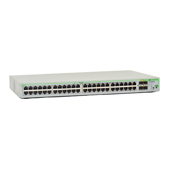
Management Software Layer 2-4 Gigabit Ethernet EcoSwitches AT-9000/28 AT-9000/28SP AT-9000/52 ◆ Command Line User’s Guide AlliedWare Plus Version 2.1.2 613-001311 Rev B... - Page 2 * Neither the name of Allied Telesis, Inc. nor the names of the respective companies above may be used to endorse or promote products derived from this software without specific prior written permission.
- Page 3 Telesis, Inc. be liable for any incidental, special, indirect, or consequential damages whatsoever, including but not limited to lost profits, arising out of or related to this manual or the information contained herein, even if Allied Telesis, Inc. has been advised of, known, or should have known, the possibility of such damages.
-
Page 5: Table Of Contents
Contents Preface ........................31 Document Conventions ............................ 32 Where to Find Web-based Guides ........................33 Contacting Allied Telesis ..........................34 Online Support ............................34 Email and Telephone Support........................34 Returning Products ............................ 34 Sales or Corporate Information ........................34 Management Software Updates......................... 34 Section I: Getting Started .................. - Page 6 Contents Chapter 2: Starting a Management Session ....................57 Starting a Local Management Session ......................58 Starting a Remote Telnet or SSH Management Session.................. 60 VTY Lines ..............................60 What to Configure First ............................. 62 Creating a Boot Configuration File ......................62 Changing the Login Password........................
- Page 7 AT-9000 Switch Command Line User’s Guide ERASE STARTUP-CONFIG .......................... 116 EXEC-TIMEOUT ............................117 HOSTNAME ..............................119 LINE CONSOLE ............................. 120 LINE VTY................................ 121 NO HOSTNAME............................. 122 PING................................123 REBOOT ................................ 124 RELOAD................................. 125 SERVICE MAXMANAGER..........................126 SHOW BAUD-RATE............................127 SHOW CLOCK ............................... 128 SHOW RUNNING-CONFIG ...........................
- Page 8 Contents SHOW INTERFACE STATUS ........................189 SHOW PLATFORM TABLE PORT .........................191 SHOW SYSTEM PLUGGABLE ........................194 SHOW SYSTEM PLUGGABLE DETAIL......................195 SHUTDOWN ..............................196 SPEED ................................197 STORM-CONTROL ............................198 Chapter 9: IPv4 and IPv6 Management Addresses ...................201 Overview .................................202 IPv4 Management Address and Default Gateway ..................205 Adding an IPv4 Management Address .....................205 Adding an IPv4 Default Gateway Address ....................207 Deleting an IPv4 Management Address and Default Gateway ..............208...
- Page 9 AT-9000 Switch Command Line User’s Guide Chapter 13: MAC Address Table ........................ 257 Overview................................. 258 Adding Static MAC Addresses ........................260 Deleting MAC Addresses ..........................261 Setting the Aging Timer ..........................263 Displaying the MAC Address Table........................ 264 Chapter 14: MAC Address Table Commands ................... 265 CLEAR MAC ADDRESS-TABLE........................
- Page 10 Contents Chapter 20: IGMP Snooping Commands ....................319 CLEAR IP IGMP .............................320 IP IGMP LIMIT ..............................321 IP IGMP QUERIER-TIMEOUT........................322 IP IGMP SNOOPING ............................323 IP IGMP SNOOPING MROUTER ........................324 IP IGMP STATUS ............................325 NO IP IGMP SNOOPING..........................326 NO IP IGMP SNOOPING MROUTER......................327 SHOW IP IGMP SNOOPING ..........................328 Chapter 21: Multicast Commands ......................331 NO SWITCHPORT BLOCK EGRESS-MULTICAST..................332...
- Page 11 AT-9000 Switch Command Line User’s Guide Uploading Files from the Switch with TFTP ..................... 377 Uploading or Downloading Files with Zmodem ....................379 Downloading Files to the Switch with Zmodem..................379 Uploading Files from the Switch with Zmodem ..................380 Downloading Files with Enhanced Stacking....................
- Page 12 Contents Chapter 34: Link Aggregation Control Protocol (LACP) ................441 Overview .................................442 LACP System Priority ..........................443 Base Port..............................443 LACP Port Priority Value ..........................443 Load Distribution Methods........................444 Guidelines..............................444 Creating New Aggregators..........................446 Setting the Load Distribution Method ......................447 Adding Ports to Aggregators ...........................448 Removing Ports from Aggregators........................449 Deleting Aggregators ............................450 Displaying Aggregators ...........................451...
- Page 13 AT-9000 Switch Command Line User’s Guide SPANNING-TREE MODE STP ........................502 SPANNING-TREE PATH-COST ........................503 SPANNING-TREE PRIORITY (Bridge Priority) ....................504 SPANNING-TREE PRIORITY (Port Priority)....................506 SPANNING-TREE STP ENABLE........................508 SPANNING-TREE STP PURGE ........................509 Chapter 39: Rapid Spanning Tree Protocol (RSTP) ................. 511 Designating RSTP as the Active Spanning Tree Protocol................
- Page 14 Contents Section VII: Virtual LANs ..................553 Chapter 41: Port-based and Tagged VLANs ....................555 Overview .................................556 Port-based VLAN Overview ..........................558 VLAN Name..............................558 VLAN Identifier ............................558 Untagged Ports............................559 Port VLAN Identifier..........................559 Guidelines to Creating a Port-based VLAN ....................560 Drawbacks of Port-based VLANs ......................560 Port-based Example 1 ..........................561 Port-based Example 2 ..........................562 Tagged VLAN Overview ..........................564...
- Page 15 AT-9000 Switch Command Line User’s Guide Chapter 44: GARP VLAN Registration Protocol Commands ..............613 GVRP APPLICANT STATE ACTIVE......................615 GVRP APPLICANT STATE NORMAL ......................616 GVRP ENABLE .............................. 617 GVRP REGISTRATION ..........................618 GVRP TIMER JOIN ............................619 GVRP TIMER LEAVE............................. 620 GVRP TIMER LEAVEALL ..........................
- Page 16 Contents Chapter 49: Voice VLAN Commands ......................673 NO SWITCHPORT VOICE VLAN ........................674 SWITCHPORT VOICE DSCP.........................675 SWITCHPORT VOICE VLAN .........................676 SWITCHPORT VOICE VLAN PRIORITY .......................678 Chapter 50: VLAN Stacking ........................679 Overview .................................680 Components..............................682 VLAN ................................682 Customer Ports............................682 Provider Ports............................682 EtherType/Length .............................682 VLAN Stacking Process ..........................683 Example of VLAN Stacking ..........................684 Chapter 51: VLAN Stacking Commands ....................689...
- Page 17 AT-9000 Switch Command Line User’s Guide Multiple Host Mode ..........................727 Multiple Supplicant Mode ......................... 727 Supplicant VLAN Attributes on the RADIUS Server................. 727 Guest VLAN..............................729 RADIUS Accounting ............................730 General Steps..............................731 Guidelines............................... 733 Enabling 802.1x Port-Based Network Access Control on the Switch............. 735 Configuring Authenticator Ports........................
- Page 18 Contents Section IX: Simple Network Management Protocols ...........787 Chapter 56: SNMPv1 and SNMPv2c ......................789 Overview .................................790 Enabling SNMPv1 and SNMPv2c ........................792 Creating Community Strings ...........................793 Adding or Removing IP Addresses of Trap or Inform Receivers ..............794 Deleting Community Strings ...........................796 Disabling SNMPv1 and SNMPv2c ........................797 Displaying SNMPv1 and SNMPv2c ........................798 Chapter 57: SNMPv1 and SNMPv2c Commands ..................801...
- Page 19 AT-9000 Switch Command Line User’s Guide Section X: Network Management ................847 Chapter 59: sFlow Agent ..........................849 Overview................................. 850 Ingress Packet Samples .......................... 850 Packet Counters............................850 Guidelines ..............................851 Configuring the sFlow Agent .......................... 852 Configuring the Ports............................853 Configuring the Sampling Rate ........................
- Page 20 Contents LLDP MED-NOTIFICATIONS .........................919 LLDP MED-TLV-SELECT ..........................920 LLDP NON-STRICT-MED-TLV-ORDER-CHECK ...................922 LLDP NOTIFICATIONS ..........................923 LLDP NOTIFICATION-INTERVAL ........................924 LLDP REINIT ..............................925 LLDP RUN ..............................926 LLDP TIMER ..............................927 LLDP TLV-SELECT ............................928 LLDP TRANSMIT RECEIVE ...........................931 LLDP TX-DELAY ............................932 LOCATION CIVIC-LOCATION ........................933 LOCATION COORD-LOCATION........................936 LOCATION ELIN-LOCATION .........................939 NO LLDP MED-NOTIFICATIONS........................940 NO LLDP MED-TLV-SELECT.........................941...
- Page 21 AT-9000 Switch Command Line User’s Guide Creating RMON Alarms ........................... 990 Creating an Alarm - Example 1 ........................ 991 Creating an Alarm - Example 2 ........................ 993 Chapter 66: RMON Commands ........................997 NO RMON ALARM............................999 NO RMON COLLECTION HISTORY ......................1000 NO RMON COLLECTION STATS........................
- Page 22 Contents MLS QOS TRUST DSCP..........................1080 NO MLS QOS ENABLE ..........................1081 NO WRR-QUEUE WEIGHT.......................... 1082 SHOW MLS QOS INTERFACE ........................1083 SHOW MLS QOS MAPS COS-QUEUE......................1086 SHOW MLS QOS MAPS DSCP-QUEUE ..................... 1087 WRR-QUEUE WEIGHT ..........................1089 Section XI: Management Security ...............1091 Chapter 70: Local Manager Accounts ......................
- Page 23 AT-9000 Switch Command Line User’s Guide Creating the Encryption Key Pair ......................... 1135 Enabling the SSH Server..........................1136 Disabling the SSH Server..........................1137 Deleting Encryption Keys ..........................1138 Displaying the SSH Server ........................... 1139 Chapter 77: SSH Server Commands ......................1141 CRYPTO KEY DESTROY HOSTKEY......................
- Page 24 Contents Specifying the Server Timeout ....................... 1195 Deleting Server IP Addresses ........................ 1195 Displaying the RADIUS Client ........................ 1196 Managing the TACACS+ Client ........................1197 Adding IP Addresses of TACACS+ Servers ................... 1197 Deleting IP Addresses of TACACS+ Servers ..................1197 Displaying the TACACS+ Client ......................
- Page 25 AT-9000 Switch Command Line User’s Guide RADIUS Client.............................. 1257 Remote Manager Account Authentication ....................1258 RMON................................1259 Secure Shell Server............................1260 sFlow Agent..............................1261 Simple Network Management Protocol (SNMPv1, SNMPv2c and SNMPv3) ..........1262 Simple Network Time Protocol ........................1263 Spanning Tree Protocols (STP and RSTP) ....................
- Page 26 Contents...
- Page 27 Tables Table 1. AlliedWare Plus Modes ............................43 Table 2. Basic Command Line Commands ........................75 Table 3. Basic Switch Management Commands ......................109 Table 4. SHOW SWITCH Command ..........................130 Table 5. SHOW USERS Command ..........................133 Table 6. Port Parameter Commands ..........................157 Table 7.
- Page 28 Tables Table 50. STP Port Parameter Commands ........................490 Table 51. Spanning Tree Protocol Commands .........................495 Table 52. STP Bridge Priority Value Increments ......................504 Table 53. STP Port Priority Value Increments ........................506 Table 54. RSTP Switch Parameters ..........................514 Table 55. RSTP Port Parameters .............................517 Table 56.
- Page 29 AT-9000 Switch Command Line User’s Guide Table 110. Access Control List Commands ........................1035 Table 111. ICMP Types ..............................1041 Table 112. Protocol Numbers ............................1050 Table 113. Quality of Service Commands ........................1069 Table 114. SHOW MLS QOS INTERFACE Command ....................1085 Table 115.
- Page 30 Tables...
-
Page 31: Preface
Preface This is the command line management guide for the AT-9000/28, AT-9000/28SP AT-9000/52 Managed Layer 2-4 Gigabit Ethernet EcoSwitches. The instructions in this guide explain how to start a management session and how to use the commands in the AlliedWare Plus™... -
Page 32: Document Conventions
Document Conventions This document uses the following conventions: Note Notes provide additional information. Caution Cautions inform you that performing or omitting a specific action may result in equipment damage or loss of data. Warning Warnings inform you that performing or omitting a specific action may result in bodily injury. -
Page 33: Where To Find Web-Based Guides
AT-9000 Switch Command Line User’s Guide Where to Find Web-based Guides The installation and user guides for all the Allied Telesis products are available for viewing in portable document format (PDF) from our web site at www.alliedtelesis.com. -
Page 34: Contacting Allied Telesis
Knowledge Base to submit questions to our technical support staff and review answers to previously asked questions. Email and For Technical Support via email or telephone, refer to the Allied Telesis web site at www.alliedtelesis.com. Select your country from the list on Telephone the web site and then select the appropriate tab. -
Page 35: Section I: Getting Started
Section I Getting Started This section contains the following chapters: Chapter 1, “AlliedWare Plus™ Command Line Interface” on page 37 Chapter 2, “Starting a Management Session” on page 57 Chapter 3, “Basic Command Line Management” on page 69 Chapter 4, “Basic Command Line Management Commands” on page... - Page 36 Section I: Getting Started...
-
Page 37: Chapter 1: Alliedware Plus™ Command Line Interface
Chapter 1 AlliedWare Plus™ Command Line Interface This chapter has the following sections: “Management Sessions” on page 38 “Management Interfaces” on page 40 “Local Manager Account” on page 41 “AlliedWare Plus™ Command Modes” on page 42 “Moving Down the Hierarchy” on page 45 “Moving Up the Hierarchy”... -
Page 38: Management Sessions
Local The switch has a Console port for local management of the unit. This port is located on the front panels on the AT-9000/28 and AT-9000/28SP Management Switches, and the rear panel on the AT-9000/52 Switch. Local management sessions, which must be performed at the unit, hence the name “local,”... - Page 39 If an intruder captures the packet with your login name and password, the security of the switch will be compromised. For secure remote management, Allied Telesis recommends Secure Shell (SSH) or secure web browser (HTTPS).
-
Page 40: Management Interfaces
Chapter 1: AlliedWare Plus™ Command Line Interface Management Interfaces The switch has two management interfaces: AlliedWare Plus™ command line Web browser windows The AlliedWare Plus command line is available from local management sessions and remote Telnet and Secure Shell management sessions. The web browser windows are available from remote web browser management sessions. -
Page 41: Local Manager Account
AT-9000 Switch Command Line User’s Guide Local Manager Account You must log on to manage the switch. This requires a valid user name and password. The switch comes with one local manager account. The user name of the account is “manager” and the default password is “friend.”... -
Page 42: Alliedware Plus™ Command Modes
Chapter 1: AlliedWare Plus™ Command Line Interface AlliedWare Plus™ Command Modes The AlliedWare Plus™ command line interface consists of a series of modes that are arranged in the hierarchy shown in Figure 1. User Executive Mode Privileged Executive Mode Global Configuration Mode Port... -
Page 43: Table 1. Alliedware Plus Modes
AT-9000 Switch Command Line User’s Guide Port Interface mode to designate the ports. The modes, their command line prompts, and their functions are listed in Table 1. Table 1. AlliedWare Plus Modes Mode Prompt Function User Exec mode awplus> Displays the switch settings. Lists the files in the file system. - Page 44 Chapter 1: AlliedWare Plus™ Command Line Interface Table 1. AlliedWare Plus Modes Mode Prompt Function Class-map mode (config-cmap)# Creates classifiers and flow groups for Quality of Service policies. Console Line mode (config-line)# Sets the session timer for local management sessions. Activates and deactivates remote manager authentication.
-
Page 45: Moving Down The Hierarchy
AT-9000 Switch Command Line User’s Guide Moving Down the Hierarchy To move down the mode hierarchy, you have to step through each mode in sequence. Skipping modes isn’t allowed. Each mode has a different command. For instance, to move from the User Exec mode to the Privileged Exec mode, you use the ENABLE command. -
Page 46: Line Console 0 Command
Chapter 1: AlliedWare Plus™ Command Line Interface LINE CONSOLE You use this command to move from the Global Configuration mode to the Console Line mode to set the management session timer and to activate 0 Command or deactivate remote authentication for local management sessions. The mode is also used to set the baud rate of the terminal port. -
Page 47: Interface Port Command
AT-9000 Switch Command Line User’s Guide This example adds to a traffic class a flow group with the ID number 1: awplus(config-pmap)# class 1 awplus(config-pmap-c)# Figure 8. CLASS Command INTERFACE You use this command to move from the Global Configuration mode to the Port Interface mode where you configure the parameter settings of the PORT Command ports and add ports to VLANs and Quality of Service policies. -
Page 48: Interface Vlan Command
Chapter 1: AlliedWare Plus™ Command Line Interface awplus(config)# vlan database awplus(config-vlan)# Figure 12. VLAN DATABASE Command INTERFACE You use this command to move from the Global Configuration mode to the VLAN Interface mode to assign the switch a management IP address. The VLAN Command format of the command is: interface vlan... -
Page 49: Location Coord-Location Command
AT-9000 Switch Command Line User’s Guide This example assigns the ID number 16 to a new LLDP civic location entry: awplus(config)# location civic-location 16 awplus(config-civic)# Figure 15. LLDP LOCATION CIVIC-LOCATION Command LOCATION You use this command to move from the Global Configuration mode to the Coordinate Location mode, to create LLDP coordinate location entries. -
Page 50: Moving Up The Hierarchy
Chapter 1: AlliedWare Plus™ Command Line Interface Moving Up the Hierarchy There are four commands for moving up the mode hierarchy. They are the EXIT, QUIT, END and DISABLE commands. EXIT and QUIT These commands, which are functionally identical, are found in nearly all the modes. -
Page 51: Disable Command
AT-9000 Switch Command Line User’s Guide User Executive Mode Privileged Executive Mode Global Configuration Mode Port VLAN Static Port Other Class-Map Line Policy Map Interface Configuration Trunk Mode Mode Modes Mode Mode Mode Mode Class Mode Figure 18. Returning to the Privileged Exec Mode with the END Command DISABLE To return to the User Exec mode from the Privileged Exec mode, use the DISABLE command. -
Page 52: Port Numbers In Commands
Chapter 1: AlliedWare Plus™ Command Line Interface Port Numbers in Commands Here is the format for port numbers in commands: port1.0. The n variable is the number of the port you want to configure on the switch. The two digits in the prefix “port1.0.” are used with modular products and with products that support stacking. -
Page 53: Combo Ports 25 To 28
AT-9000 Switch Command Line User’s Guide Combo Ports 25 to 28 Ports 25 to 28 on the AT-9000/28 and AT-9000/28SP Managed Layer 2 ecoSwitches are combo ports. Each combo consists of one 10/100/ 1000Base-T port and one SFP slot. The twisted pair ports have the letter R for Redundant as part of their port numbers on the front faceplates of the units. -
Page 54: Command Format
Chapter 1: AlliedWare Plus™ Command Line Interface Command Format The following sections describe the command line interface features and the command syntax conventions. Command Line The command line interface has these features: Interface Command history - Use the up and down arrow keys. Features Keyword abbreviations - Any keyword can be recognized by typing an unambiguous prefix, for example, type “sh”... -
Page 55: Startup Messages
AT-9000 Switch Command Line User’s Guide Startup Messages The switch generates the following series of status messages whenever it is powered on or reset. The messages can be view on the Console port with a terminal or a computer with a terminal emulator program. awplus# umount: none busy - remounted read-only umount: cannot remount rootfs read-only umount: cannot umount /: Device or resource busy... - Page 56 Chapter 1: AlliedWare Plus™ Command Line Interface Initializing SYS_MGMT ......done! Initializing SWITCH_MGMT ....... done! Initializing L2APP_MGMT ......done! Initializing SNMP_MGMT ......done! Initializing Authentication ....done! Initializing TCPIP ......done! Initializing Default VLAN ..... done! Initializing ENCO ......done! Initializing PKI .......
-
Page 57: Chapter 2: Starting A Management Session
Chapter 2 Starting a Management Session This chapter has the following sections: “Starting a Local Management Session” on page 58 “Starting a Remote Telnet or SSH Management Session” on page 60 “What to Configure First” on page 62 “Ending a Management Session” on page 67 Note The initial configuration of the switch must be from a local management session. -
Page 58: Starting A Local Management Session
1. Connect the RJ-45 connector on the management cable that comes with the switch to the Console port, as shown in Figure 22. The Console port is located on the front panels on the AT-9000/28 and AT-9000/28SP Switches and on the back panel on the AT-9000/52 Switch. - Page 59 AT-9000 Switch Command Line User’s Guide 5. Enter a user name and password. If this is the initial management session of the switch, enter “manager” as the user name “friend” as the password. The user name and password are case sensitive. The local management session has started when the AlliedWare Plus™...
-
Page 60: Starting A Remote Telnet Or Ssh Management Session
Chapter 2: Starting a Management Session Starting a Remote Telnet or SSH Management Session Here are the requirements for remote management of the switch from a Telnet or SSH client on your network: You must assign the switch a management IP address. To initially assign the switch an address, use a local management session. - Page 61 AT-9000 Switch Command Line User’s Guide sessions. Or, if there is already one active management session, a new session is assigned line 1, and so on. You can adjust these three parameters on the individual lines: Management session timer - This timer is used by the switch to end inactive management sessions, automatically.
-
Page 62: What To Configure First
Chapter 2: Starting a Management Session What to Configure First Here are a few suggestions on what to configure during your initial management session of the switch. The initial management session must be a local management session from the Console port on the switch. For instructions on how to start a local management session, refer to “Starting a Local Management Session”... -
Page 63: Changing The Login Password
If you forget the manager password, you will not be able to manage the switch if there are no other management accounts on the unit, and will have to contact Allied Telesis Technical Support for assistance. For instructions on how to create additional management accounts, refer to Chapter 70, “Local Manager Accounts”... -
Page 64: Adding A Management Ip Address
Chapter 2: Starting a Management Session marks are not permitted. This example assigns the name “Engineering_sw2” to the switch: awplus> enable awplus# configure terminal awplus(config)# hostname Engineering_sw2 Engineering_sw2(config)# Adding a You must assign the switch a management IP address to use the features in Table 11 on page 202. - Page 65 AT-9000 Switch Command Line User’s Guide Use the INTERFACE VLAN command to awplus(config)# interface vlan1 move to the VLAN Interface mode of the Default_VLAN. Assign the management IPv4 address to awplus(config-if)# ip address the switch using the IP ADDRESS 149.82.112.72/24 command.
-
Page 66: Saving Your Changes
Chapter 2: Starting a Management Session Activate the DHCP client on the switch awplus(config-if)# ip address dhcp with the IP ADDRESS DHCP command. Return to the Global Configuration mode. awplus(config-if)# end Verify the new management IPv4 address awplus# show ip route and default gateway with the SHOW IP ROUTE command. -
Page 67: Ending A Management Session
AT-9000 Switch Command Line User’s Guide Ending a Management Session To end a management session from below the Privileged Exec mode, return to the Privileged Exec mode and enter EXIT: awplus(config)# exit awplus# exit To end a management session from the User Exec mode, enter the LOGOUT or EXIT command: awplus>... - Page 68 Chapter 2: Starting a Management Session Section I: Getting Started...
-
Page 69: Chapter 3: Basic Command Line Management
Chapter 3 Basic Command Line Management “Clearing the Screen” on page 70 “Displaying the On-line Help” on page 71 “Saving Your Configuration Changes” on page 73 “Ending a Management Session” on page 74... -
Page 70: Clearing The Screen
Chapter 3: Basic Command Line Management Clearing the Screen If your screen becomes cluttered with commands, you can start fresh by entering the CLEAR SCREEN command in the User Exec or Privileged Exec mode. If you’re in a lower mode, you’ll have to move up the mode hierarchy to one of these modes to use the command. -
Page 71: Displaying The On-Line Help
AT-9000 Switch Command Line User’s Guide Displaying the On-line Help The command line interface has an on-line help system to assist you with the commands. The help system is displayed by typing a question mark. Typing a question mark at a command line prompt displays all the keywords in the current mode. - Page 72 Chapter 3: Basic Command Line Management awplus> enable awplus> enable awplus# configure terminal awplus# configure terminal awplus(config)# hostname ? awplus(config)# hostname ? <STRING:sysName> <STRING:sysName> Figure 27. Displaying the Class of a Parameter Section I: Getting Started...
-
Page 73: Saving Your Configuration Changes
AT-9000 Switch Command Line User’s Guide Saving Your Configuration Changes To permanently save your changes to the parameter settings on the switch, you must update the active boot configuration file. This is accomplished with either the WRITE command or the COPY RUNNING- CONFIG STARTUP-CONFIG command, both of which are found in the Privileged Exec mode. -
Page 74: Ending A Management Session
Chapter 3: Basic Command Line Management Ending a Management Session To end a management session from the Privileged Exec mode, enter the EXIT command: awplus(config)# exit awplus# exit To end a management session from the User Exec mode, enter LOGOUT or EXIT: awplus>... -
Page 75: Chapter 4: Basic Command Line Management Commands
Chapter 4 Basic Command Line Management Commands The basic command line commands are summarized in Table 2. Table 2. Basic Command Line Commands Command Mode Description “? (Question Mark Key)” on page 77 All modes Displays the on-line help. “CLEAR SCREEN” on page 79 User Exec and Clears the screen. - Page 76 Chapter 4: Basic Command Line Management Commands Table 2. Basic Command Line Commands Command Mode Description “QUIT” on page 90 All modes Moves you up one mode. except the User Exec and Privileged Exec “TERMINAL LENGTH” on page 91 Privileged Exec Specifies the maximum number of lines that the SHOW commands display at one time on the screen.
-
Page 77: (Question Mark Key)
AT-9000 Switch Command Line User’s Guide ? (Question Mark Key) Syntax Parameters None. Modes All modes Description Use the question mark key to display on-line help messages. Typing the key at different points in a command displays different messages: Typing “?” at a command line prompt displays all the keywords in the current mode. - Page 78 Chapter 4: Basic Command Line Management Commands awplus> enable awplus# configure terminal awplus(config)# spanning-tree hello-time ? Section I: Getting Started...
-
Page 79: Clear Screen
AT-9000 Switch Command Line User’s Guide CLEAR SCREEN Syntax clear screen Parameters None. Modes User Exec and Privileged Exec modes Description Use this command to clear the screen. Example awplus# clear screen Section I: Getting Started... -
Page 80: Configure Terminal
Chapter 4: Basic Command Line Management Commands CONFIGURE TERMINAL Syntax configure terminal Parameters None. Mode Privileged Exec mode Description Use this command to move from the Privileged Exec mode to the Global Configuration mode. Example awplus# configure terminal awplus(config)# Section I: Getting Started... -
Page 81: Copy Running-Config Startup-Config
AT-9000 Switch Command Line User’s Guide COPY RUNNING-CONFIG STARTUP-CONFIG Syntax copy running-config startup-config Parameters None. Mode Privileged Exec mode Description Use this command to update the active boot configuration file with the switch’s current configuration, for permanent storage. When you enter the command, the switch copies its parameter settings into the active boot configuration file. -
Page 82: Disable
Chapter 4: Basic Command Line Management Commands DISABLE Syntax disable Parameters None. Mode Privileged Exec mode Description Use this command to return to the User Exec mode from the Privileged Exec mode. Example awplus# disable awplus> Section I: Getting Started... - Page 83 AT-9000 Switch Command Line User’s Guide Syntax Parameters None. Mode Global Configuration mode Description Use this command to perform commands in the Privileged Exec mode from the Global Configuration mode. Example This example performs the SHOW INTERFACE command for port 4 from the Global Configuration mode: awplus(config)# do show interface port1.0.4 Section I: Getting Started...
-
Page 84: Enable
Chapter 4: Basic Command Line Management Commands ENABLE Syntax enable Parameters None. Mode User Exec mode Description Use this command to move from the User Exec mode to the Privileged Exec mode. Example awplus> enable awplus# Section I: Getting Started... -
Page 85: End
AT-9000 Switch Command Line User’s Guide Syntax Parameters None. Mode All modes below the Global Configuration mode. Description Use this command to return to the Privileged Exec mode. Example awplus(config-if)# end awplus# Section I: Getting Started... -
Page 86: Exit
Chapter 4: Basic Command Line Management Commands EXIT Syntax exit Parameters None. Mode All modes except the User Exec and Privileged Exec modes. Description Use this command to move up one mode in the mode hierarchy. This command is identical to the QUIT command. Example awplus(config)# exit awplus#... -
Page 87: Length
AT-9000 Switch Command Line User’s Guide LENGTH Syntax value length Parameters value Specifies the maximum number of lines that the SHOW commands display at one time on the screen. The range is 0 to 512 lines. Use the value 0 if you do not want the SHOW commands to pause. - Page 88 Chapter 4: Basic Command Line Management Commands awplus(config)# line console 0 awplus(config-line)# no length Section I: Getting Started...
-
Page 89: Logout
AT-9000 Switch Command Line User’s Guide LOGOUT Syntax logout Parameters None. Mode User Exec mode Description Use this command to end a management session. Example This example shows the sequence of commands to logout starting from the Global Configuration mode: awplus(config)# exit awplus# disable awplus>... -
Page 90: Quit
Chapter 4: Basic Command Line Management Commands QUIT Syntax quit Parameters None. Mode All modes except the User Exec and Privileged Exec modes. Description Use this command to move up one mode in the mode hierarchy. This command is identical to the EXIT command. Example awplus(config)# quit awplus#... -
Page 91: Terminal Length
AT-9000 Switch Command Line User’s Guide TERMINAL LENGTH Syntax value terminal length Parameters value Specifies the maximum number of lines that the SHOW commands display at one time on the screen. The range is 0 to 512 lines. Use the value 0 if you do not want the SHOW commands to pause. -
Page 92: Write
Chapter 4: Basic Command Line Management Commands WRITE Syntax write Parameters None. Mode Privileged Exec mode Description Use this command to update the active boot configuration file with the switch’s current configuration, for permanent storage. When you enter the command, the switch copies its parameter settings into the active boot configuration file. -
Page 93: Section Ii: Basic Operations
Section II Basic Operations This section contains the following chapters: Chapter 5, “Basic Switch Management” on page 95 Chapter 6, “Basic Switch Management Commands” on page 109 Chapter 7, “Port Parameters” on page 139 Chapter 8, “Port Parameter Commands” on page 157 Chapter 9, “IPv4 and IPv6 Management Addresses”... - Page 94 Section II: Basic Operations...
-
Page 95: Chapter 5: Basic Switch Management
Chapter 5 Basic Switch Management “Adding a Name to the Switch” on page 96 “Adding Contact and Location Information” on page 97 “Displaying Parameter Settings” on page 98 “Manually Setting the Date and Time” on page 99 “Pinging Network Devices” on page 100 “Resetting the Switch”... -
Page 96: Adding A Name To The Switch
Chapter 5: Basic Switch Management Adding a Name to the Switch The switch will be easier to identify if you assign it a name. The switch displays its name in the command line prompt, in place of the default prefix “awplus.” To assign the switch a name, use the HOSTNAME command in the Global Configuration mode. -
Page 97: Adding Contact And Location Information
AT-9000 Switch Command Line User’s Guide Adding Contact and Location Information The commands for assigning the switch contact and location information are the SNMP-SERVER CONTACT and SNMP-SERVER LOCATION commands, both of which are found in the Global Configuration mode. Here are the formats of the commands: contact contact snmp-server location... -
Page 98: Displaying Parameter Settings
Chapter 5: Basic Switch Management Displaying Parameter Settings To display the current parameter settings on the switch, use the SHOW RUNNING-CONFIG command in the Privileged Exec mode. The settings, which are displayed in their equivalent command line commands, are limited to just those parameters that have been changed from their default values. -
Page 99: Manually Setting The Date And Time
AT-9000 Switch Command Line User’s Guide Manually Setting the Date and Time To manually set the date and time on the switch, use the CLOCK SET command in the Privileged Exec mode. Here is the format of the command: hh:mm:ss dd mm yyyy clock set Here are the variables: hh:mm:ss: Use this variable to specify the hour, minute, and second... -
Page 100: Pinging Network Devices
Chapter 5: Basic Switch Management Pinging Network Devices If the switch is unable to communicate with a network device, such as a syslog server or a TFTP server, you can test for an active link between the two devices by instructing the switch to send ICMP Echo Requests and to listen for replies sent back from the other device. -
Page 101: Resetting The Switch
AT-9000 Switch Command Line User’s Guide Resetting the Switch To reset the switch, use either the REBOOT or RELOAD command in the Privileged Exec mode. You might reset the switch if it is experiencing a problem or if you want to reconfigure its settings after designating a new active boot configuration file. -
Page 102: Restoring The Default Settings To The Switch
Chapter 5: Basic Switch Management Restoring the Default Settings to the Switch Caution Restoring the default settings requires that you reset the switch. The unit will not forward network traffic while it initializes the management software. Some network traffic may be lost. To restore the default settings to the switch, delete or rename the active boot configuration file and then reset the unit. - Page 103 AT-9000 Switch Command Line User’s Guide sequence of commands and messages: awplus> enable awplus# erase startup-config erase start-up config? (y/n):y Deleting.. Successful Operation awplus# reboot If you prefer to keep the active boot configuration file, you can rename it with the MOVE command in the Privileged Exec mode, and then reset the switch.
-
Page 104: Setting The Baud Rate Of The Console Port
Chapter 5: Basic Switch Management Setting the Baud Rate of the Console Port The Console port is used for local management of the switch. To set its baud rate, use the BAUD-RATE SET command in the Global Configuration mode. Note If you change the baud rate of the Console port during a local management session, your session is interrupted. -
Page 105: Configuring The Management Session Timers
AT-9000 Switch Command Line User’s Guide Configuring the Management Session Timers You should always conclude a management session by logging off so that if you leave your workstation unattended, someone cannot use it to change the switch’s configuration. If you forget to log off, the switch has management session timers to detect and log off inactive local and remote management sessions for you, automatically. -
Page 106: Setting The Maximum Number Of Manager Sessions
Chapter 5: Basic Switch Management Setting the Maximum Number of Manager Sessions The switch supports up to three manager sessions simultaneously so that more than one person can manage the unit at a time. You set the maximum number of sessions with the SERVICE MAXMANAGER command in the Global Configuration mode. -
Page 107: Configuring The Banners
AT-9000 Switch Command Line User’s Guide Configuring the Banners The switch has three banner messages you may use to identify the switch or to display other information about the unit. The banners are listed here: Message-of-the-day banner Login banner User Exec and Privileged Exec modes banner Message-of-the-day This unit was updated to version 2.1.1 today, May 21, banner... - Page 108 Chapter 5: Basic Switch Management return to the command prompt in the Global Configuration mode. This example of the BANNER MOTD command assigns the switch the message-of-the-day banner in Figure 30: awplus> enable awplus# configure terminal awplus(config)# banner motd Type CTRL/D to finish This unit was updated to version 2.1.1 today, May 21, 2010.
-
Page 109: Chapter 6: Basic Switch Management Commands
Chapter 6 Basic Switch Management Commands The basic switch management commands are summarized in Table 3. Table 3. Basic Switch Management Commands Command Mode Description “BANNER EXEC” on page 111 Global Creates a User Exec and Privileged Configuration Exec modes banner. “BANNER LOGIN”... - Page 110 Chapter 6: Basic Switch Management Commands Table 3. Basic Switch Management Commands Command Mode Description “SHOW BAUD-RATE” on page 127 Global Displays the settings of the Console Configuration port. “SHOW CLOCK” on page 128 User Exec and Displays the date and time. Privileged Exec “SHOW RUNNING-CONFIG”...
-
Page 111: Banner Exec
AT-9000 Switch Command Line User’s Guide BANNER EXEC Syntax banner exec Parameters None. Mode Global Configuration mode Description Use this command to create a banner for the User Exec and Privilege Exec modes. The message is displayed above the command line prompt when you log on or clear the screen with the CLEAR SCREEN command, in local, Telnet and SSH management sessions. -
Page 112: Banner Login
Chapter 6: Basic Switch Management Commands BANNER LOGIN Syntax banner login Parameters None. Mode Global Configuration mode Description Use this command to configure the login banner. The message is displayed prior to the login user name and password prompts for local, Telnet and SSH management sessions. -
Page 113: Banner Motd
AT-9000 Switch Command Line User’s Guide BANNER MOTD Syntax banner motd Parameters None. Mode Global Configuration mode Description Use this command to create a message-of-the-day banner. The message is displayed prior to the login user name and password prompts for local, Telnet and SSH management sessions. -
Page 114: Baud-Rate Set
Chapter 6: Basic Switch Management Commands BAUD-RATE SET Syntax baud-rate set 1200|2400|4800|9600|19200|38400|57600|115200 Parameters None. Mode Global Configuration mode Description Use this command to set the baud rate of the Console port, which is used for local management sessions of the switch. Note If you change the baud rate of the serial terminal port during a local management session, your session will be interrupted. -
Page 115: Clock Set
AT-9000 Switch Command Line User’s Guide CLOCK SET Syntax hh:mm:ss dd mm yyyy clock set Parameters hh:mm:ss Specifies the hour, minute, and second for the switch’s time in 24-hour format. Specifies the day of the month. The day must be entered in two digits. -
Page 116: Erase Startup-Config
Chapter 6: Basic Switch Management Commands ERASE STARTUP-CONFIG Syntax erase startup-config Parameters None. Mode Privileged Exec mode Description Use this command to delete the active boot configuration file to restore the default settings to all the parameters on the switch. After entering this command, enter the REBOOT command to reset the switch and restore the default settings. -
Page 117: Exec-Timeout
AT-9000 Switch Command Line User’s Guide EXEC-TIMEOUT Syntax value exec-timeout Parameters exec-timeout Specifies the session timer in minutes. The range is 1 to 60 minutes. The default value is 10 minutes. Mode Line Console and Virtual Terminal Line modes Description Use this command to set the management session timers. - Page 118 Chapter 6: Basic Switch Management Commands awplus> enable awplus# configure terminal awplus(config)# line vty 0 awplus(config-line)# exec-timeout 5 Section II: Basic Operations...
-
Page 119: Hostname
AT-9000 Switch Command Line User’s Guide HOSTNAME Syntax name hostname Parameters name Specifies a name of up to 39 alphanumeric characters for the switch. A name may contain special characters, except for spaces and quotation marks. Mode Global Configuration mode Description Use this command to assign the switch a name. -
Page 120: Line Console
Chapter 6: Basic Switch Management Commands LINE CONSOLE Syntax line console 0 Parameters None. Mode Global Configuration mode Description Use this command to enter the Line Console mode to set the session timer and to activate or deactivate remote authentication for local management sessions. -
Page 121: Line Vty
AT-9000 Switch Command Line User’s Guide LINE VTY Syntax line_id line vty Parameters line_id Specifies the number of a VTY line. The range is 0 to 9. You can specify just one line at a time. Mode Global Configuration mode Description Use this command to enter the Virtual Terminal Line mode for a VTY line, to set the session timer or to activate or deactivate remote authentication... -
Page 122: No Hostname
Chapter 6: Basic Switch Management Commands NO HOSTNAME Syntax hostname Parameters None. Mode Global Configuration mode Description Use this command to delete the switch’s name without assigning a new name. Example This example deletes the current name of the switch without assigning a new value: Bld2_Shipping>... -
Page 123: Ping
AT-9000 Switch Command Line User’s Guide PING Syntax ipaddress ping Parameters ipaddress Specifies the IP address of the network device to receive the ICMP Echo Requests from the switch. You can specify only one IP address. Modes Privileged Exec mode Description Use this command to instruct the switch to send ICMP Echo Requests to network devices. -
Page 124: Reboot
Chapter 6: Basic Switch Management Commands REBOOT Syntax reboot Parameters None. Mode Privileged Exec mode Description Use this command to reset the switch. You might reset the unit if it is experiencing a problem or if you want to reconfigure its settings after you designate a new active boot configuration file.This command is identical to “RELOAD”... -
Page 125: Reload
AT-9000 Switch Command Line User’s Guide RELOAD Syntax reload Parameters None. Mode Privileged Exec mode Description Use this command to reset the switch. You might reset the unit if it is experiencing a problem or if you want to reconfigure its settings after you designate a new active boot configuration file. -
Page 126: Service Maxmanager
Chapter 6: Basic Switch Management Commands SERVICE MAXMANAGER Syntax value service maxmanager Parameters value Specifies the maximum number of manager sessions the switch will allow at one time. The range is 1 to 3. The default is 1. Mode Global Configuration mode Description Use this command to set the maximum number of manager sessions that can be open on the switch simultaneously. -
Page 127: Show Baud-Rate
AT-9000 Switch Command Line User’s Guide SHOW BAUD-RATE Syntax show baud-rate Parameters None. Mode User Exec mode and Privileged Exec mode Description Use this command to display the settings of the Console port, used for local management sessions of the switch. Here is an example of the information. -
Page 128: Show Clock
Chapter 6: Basic Switch Management Commands SHOW CLOCK Syntax show clock Parameters None. Modes User Exec mode Description Use this command to display the system’s current date and time. Example awplus# show clock Section II: Basic Operations... -
Page 129: Show Running-Config
AT-9000 Switch Command Line User’s Guide SHOW RUNNING-CONFIG Syntax show running-config Parameters None. Modes Privileged Exec mode Description Use this command to display the settings of the switch, in their equivalent command line commands. The settings the command displays are those that have been changed from their default values and include those values that have not yet been saved in the active boot configuration file. -
Page 130: Show Switch
Description Application Software The version number of the management Version software. Application Software Build The date and time when Allied Telesis Date released this version of the management software. MAC Address The MAC address of the switch. Section II: Basic Operations... - Page 131 AT-9000 Switch Command Line User’s Guide Table 4. SHOW SWITCH Command Parameter Description Console Disconnect Timer The current setting of the console timer. Interval The switch uses the console timer to end inactive management session. The switch ends management sessions if they are inactive for the length of the timer.
-
Page 132: Show System
Use this command to view general information about the switch. Figure 33 is an example of the information. Switch System Status Sat, 01 Jan 2000 00:37:26 Board Board Name Serial Number ------------------------------------------------------------------------ Base AT-9000/28 A04161H090200007 ----------------------------------------------------------------------- Environmental Status : Normal Uptime : 0 days 00:37:27 Bootloader version : 5.0.4 Software version : 2.1.1... -
Page 133: Show Users
AT-9000 Switch Command Line User’s Guide SHOW USERS Syntax show users Parameters None. Modes Privileged Exec mode Description Use this command to display the managers who are currently logged on the switch. The command lists managers who are logged on locally through the Console port and remotely from Telnet and SSH sessions. - Page 134 Chapter 6: Basic Switch Management Commands Table 5. SHOW USERS Command Parameter Description Idle The number of hours, minutes, and seconds since the manager to whom the account belongs to entered a command on the switch. The value will always be zero for the account you are currently using to manage the switch.
-
Page 135: Snmp-Server Contact
AT-9000 Switch Command Line User’s Guide SNMP-SERVER CONTACT Syntax contact snmp-server contact Parameters contact Specifies the name of the person responsible for managing the switch. The name can be up to 39 alphanumeric characters in length. Spaces and special characters are allowed. Mode Global Configuration mode Description... -
Page 136: Snmp-Server Location
Chapter 6: Basic Switch Management Commands SNMP-SERVER LOCATION Syntax location snmp-server location Parameters location Specifies the location of the switch. The location can be up to 39 alphanumeric characters. Spaces and special characters are allowed. Mode Global Configuration mode Description Use this command to add location information to the switch. -
Page 137: System Territory
AT-9000 Switch Command Line User’s Guide SYSTEM TERRITORY Syntax territory system territory Parameters territory Specifies the territory of the switch. The switch can have only one territory. You may choose from the following territories: australia Australia china China europe Europe japan Japan korea... - Page 138 Chapter 6: Basic Switch Management Commands awplus# configure terminal awplus(config)# no system territory Section II: Basic Operations...
-
Page 139: Chapter 7: Port Parameters
Chapter 7 Port Parameters “Adding Descriptions” on page 140 “Setting the Speed and Duplex Mode” on page 141 “Setting the MDI/MDI-X Wiring Configuration” on page 143 “Enabling or Disabling Ports” on page 144 “Enabling or Disabling Backpressure” on page 145 “Enabling or Disabling Flow Control”... -
Page 140: Adding Descriptions
Chapter 7: Port Parameters Adding Descriptions The ports will be easier to identify if you give them descriptions. The descriptions are viewed with the SHOW INTERFACE command in the Privileged Exec mode. The command for adding descriptions is the DESCRIPTION command in the Port Interface mode. -
Page 141: Setting The Speed And Duplex Mode
AT-9000 Switch Command Line User’s Guide Setting the Speed and Duplex Mode The twisted pair ports on the switch can operate at 10, 100, or 1000 Mbps, in either half-duplex or full-duplex mode. You may set the speeds and duplex modes yourself or, since the ports support Auto-Negotiation, you may let the switch configure the ports automatically. - Page 142 Chapter 7: Port Parameters awplus# configure terminal awplus(config)# interface port1.0.11,port1.0.17 awplus(config-if)# speed 100 This example configures port 1 to half-duplex: awplus> enable awplus# configure terminal awplus(config)# interface port1.0.1 awplus(config-if)# duplex half This example configures ports 2 to 4 to 10 Mbps, full-duplex: awplus>...
-
Page 143: Setting The Mdi/Mdi-X Wiring Configuration
AT-9000 Switch Command Line User’s Guide Setting the MDI/MDI-X Wiring Configuration The wiring configurations of twisted pair ports that operate at 10 or 100 Mbps are MDI (medium dependent interface) and MDI-X (medium dependent interface crossover). A port on the switch and a port on a link partner must have different settings. -
Page 144: Enabling Or Disabling Ports
Chapter 7: Port Parameters Enabling or Disabling Ports Disabling ports turns off their receivers and transmitters so that they cannot forward traffic. You might disable unused ports on the switch to protect them from unauthorized use, or if there is a problem with a cable or a network device. -
Page 145: Enabling Or Disabling Backpressure
AT-9000 Switch Command Line User’s Guide Enabling or Disabling Backpressure Ports use backpressure during periods of packet congestion, to prevent packet overruns. They use it to stop their link partners from sending any further packets to enable them to process the packets already in their buffers. -
Page 146: Enabling Or Disabling Flow Control
Chapter 7: Port Parameters Enabling or Disabling Flow Control When a port that is operating in full-duplex mode needs to temporarily stop its local or remote counterpart from sending any further packets, it initiates flow control by sending what are known as pause packets. Pause packets instruct the link partner to stop sending packets to allow the sender of the packets time to process the packets already stored in its buffers. - Page 147 AT-9000 Switch Command Line User’s Guide This example configures port 21 not to send pause packets during periods of packet congestion: awplus> enable awplus# configure terminal awplus(config)# interface port1.0.21 awplus(config-if)# speed 100 awplus(config-if)# duplex full awplus(config-if)# flowcontrol send off This example enables both the receive and send portions of flow control on port 7: awplus>...
- Page 148 Chapter 7: Port Parameters If flow control isn’t configured on a port, this message is displayed: Flow control is not set on interface port1.0.2 Section II: Basic Operations...
-
Page 149: Resetting Ports
AT-9000 Switch Command Line User’s Guide Resetting Ports If a port is experiencing a problem, you may be able to correct it with the RESET command in the Port Interface mode. This command performs a hardware reset. The port parameter settings are retained. The reset takes just a second or two to complete. -
Page 150: Configuring Threshold Limits For Ingress Packets
Chapter 7: Port Parameters Configuring Threshold Limits for Ingress Packets You can set threshold limits for the ingress packets on the ports. The threshold limits control the number of packets the ports accept each second. Packets that exceed the limits are discarded by the ports. You can set different limits for broadcast, multicast, and unknown unicast traffic. - Page 151 AT-9000 Switch Command Line User’s Guide awplus(config-if)# no storm-control broadcast This example disables unknown unicast rate limiting on port 5, 6, and 15: awplus> enable awplus# configure terminal awplus(config)# interface port1.0.5,port1.0.6,port1.0.15 awplus(config-if)# no storm-control dlf This example removes the threshold limit for multicast packets on port 23: awplus>...
-
Page 152: Reinitializing Auto-Negotiation
Chapter 7: Port Parameters Reinitializing Auto-Negotiation If you believe that a port set to Auto-Negotiation is not using the highest possible common speed and duplex-mode between itself and a network device, you can instruction it to repeat Auto-Negotiation. This is accomplished with the RENEGOTIATE command in the Port Interface mode. -
Page 153: Restoring The Default Settings
AT-9000 Switch Command Line User’s Guide Restoring the Default Settings To restore the default settings on a port, use the PURGE command in the Port Interface mode. This example returns ports 12, 13 and 15 to their default settings: awplus> enable awplus# configure terminal awplus(config)# interface port1.0.12,port1.0.13,port1.0.15 awplus(config-if)# purge... -
Page 154: Displaying Port Settings
Chapter 7: Port Parameters Displaying Port Settings To display the speed and duplex mode settings of the ports, use the SHOW INTERFACE STATUS command in the Privileged Exec mode. Here is the format: port show interface [ ] status This example of the command displays the speed and duplex mode settings for ports 18 and 20: awplus# show interface port1.0.18,port1.0.20 status Here is an example of the information the command displays. - Page 155 AT-9000 Switch Command Line User’s Guide Bandwidth 1g input packets 0, bytes 0, dropped 0, multicast packets 0 output packets 0, bytes 0, multicast packets 0 broadcast packets 0 Figure 38. SHOW INTERFACE Command (Continued) The fields are described in Table 8 on page 187. Section II: Basic Operations...
-
Page 156: Displaying Or Clearing Port Statistics
Chapter 7: Port Parameters Displaying or Clearing Port Statistics To view packet statistics for the individual ports, use the SHOW PLATFORM TABLE PORT command in the Privileged Exec mode. Here is the format of the command: port show platform table port [ ] counters This example displays the statistics for ports 23 and 24: awplus# show platform table port port1.0.23,port1.0.24... -
Page 157: Chapter 8: Port Parameter Commands
Chapter 8 Port Parameter Commands The port parameter commands are summarized in Table 6. Table 6. Port Parameter Commands Command Mode Description “BACKPRESSURE” on page 159 Port Interface Enables or disables backpressure on ports that are operating in half-duplex mode. “BPLIMIT”... - Page 158 Chapter 8: Port Parameter Commands Table 6. Port Parameter Commands Command Mode Description “NO STORM-CONTROL” on Port Interface Removes threshold limits for page 178 broadcast, multicast, or unknown unicast packets. “POLARITY” on page 179 Port Interface Sets the MDI/MDI-X settings on twisted pair ports.
-
Page 159: Backpressure
AT-9000 Switch Command Line User’s Guide BACKPRESSURE Syntax backpressure on|off Parameters Activates backpressure on the ports. Deactivates backpressure on the ports. Mode Port Interface mode Description Use this command to enable or disable backpressure on ports that are operating at 10 or 100 Mbps in half-duplex mode. Backpressure is used by ports during periods of packet congestion to temporarily stop their network counterparts from transmitting more packets. - Page 160 Chapter 8: Port Parameter Commands awplus> enable awplus# configure terminal awplus(config)# interface port1.0.8,port1.0.21 awplus(config-if)# speed 100 awplus(config-if)# duplex half awplus(config-if)# backpressure off Section II: Basic Operations...
-
Page 161: Bplimit
AT-9000 Switch Command Line User’s Guide BPLIMIT Syntax bplimit bplimit Parameters bplimit Specifies the number of cells for backpressure. A cell represents 128 bytes. The range is 1 to 7935 cells. The default value is 7935 cells. Mode Port Interface mode Description Use this command to specify a threshold level for backpressure on a port. -
Page 162: Clear Port Counter
Chapter 8: Port Parameter Commands CLEAR PORT COUNTER Syntax clear port counter port Parameters port Specifies the port whose packet counters you want to clear. You can specify more than one port at a time in the command. Mode User Exec mode and Privileged Exec mode Description Use this command to clear the packet counters of the ports. -
Page 163: Description
AT-9000 Switch Command Line User’s Guide DESCRIPTION Syntax description description Parameters description Specifies a description of 1 to 80 alphanumeric characters for a port. Spaces and special characters are allowed. Mode Port Interface mode Description Use this command to add descriptions to the ports on the switch. The ports will be easier to identify if they have descriptions. -
Page 164: Duplex
Chapter 8: Port Parameter Commands DUPLEX Syntax duplex auto|half|full Parameters auto Activates Auto-Negotiation for the duplex mode, so that the duplex mode is set automatically. half Specifies half-duplex mode. full Specifies full-duplex mode. Mode Port Interface mode Description Use this command to set the duplex modes of the twisted pair ports. Ports operating in half-duplex mode can either receive packets or transmit packets, but not both at the same time, while ports operating in full-duplex can both send and receive packets, simultaneously. - Page 165 AT-9000 Switch Command Line User’s Guide awplus# configure terminal awplus(config)# interface port1.0.11 awplus(config-if)# duplex half This example configures the duplex mode with Auto-Negotiation on port awplus> enable awplus# configure terminal awplus(config)# interface port1.0.15 awplus(config-if)# duplex auto Section II: Basic Operations...
-
Page 166: Egress-Rate-Limit
Chapter 8: Port Parameter Commands EGRESS-RATE-LIMIT Syntax egress-rate-limit value Parameters value Specifies the maximum amount of traffic that can be transmitted from the port. The value is kilobits per second. The range is 64 to 1,000,000,000 kilobits per second. Mode Port Interface mode Description Use this command to set a limit on the amount of traffic that can be... -
Page 167: Fctrllimit
AT-9000 Switch Command Line User’s Guide FCTRLLIMIT Syntax fctrllimit fctrllimit Parameters fctrllimit Specifies the number of cells for flow control. A cell represents 128 bytes. The range is 1 to 7935 cells. The default value is 7935 cells. Mode Port Interface mode Description Use this command to specify threshold levels for flow control on the ports. -
Page 168: Flowcontrol
Chapter 8: Port Parameter Commands FLOWCONTROL Syntax flowcontrol send|receive|both on|off Parameter send Controls whether a port sends pause packets during periods of packet congestion, to initiate flow control. receive Controls whether a port, when it receives pause packets from its network counterpart, stops sending packets. - Page 169 AT-9000 Switch Command Line User’s Guide The SEND parameter determines whether a port sends pause packets when it experiences traffic congestion. If send is on, a port sends pause packets to signal its link partner of the condition and to stop the transmission of more packets.
- Page 170 Chapter 8: Port Parameter Commands awplus(config-if)# duplex full awplus(config-if)# flowcontrol send off awplus(config-if)# flowcontrol receive on Section II: Basic Operations...
-
Page 171: Holbplimit
AT-9000 Switch Command Line User’s Guide HOLBPLIMIT Syntax holbplimit holbplimit Parameter Specifies the threshold at which a port signals a head of holbplimit line blocking event. The threshold is specified in cells. A cell is 128 bytes. The range is 1 to 8,191 cells; the default is 682. - Page 172 Chapter 8: Port Parameter Commands Port A Port C C C C C D D D D Ingress Queue Egress Queue Port B Port D 100% D D D D D D D D D D D D D D D D Ingress Queue Engress Queue Figure 39.
-
Page 173: Linktrap
AT-9000 Switch Command Line User’s Guide LINKTRAP Syntax linktrap Parameter None. Mode Port Interface mode Description Use this command to activate SNMP link traps on the ports. The switch sends an SNMP trap to an SNMP trap receiver on your network whenever a port experiences a change in its link state. -
Page 174: No Egress-Rate-Limit
Chapter 8: Port Parameter Commands NO EGRESS-RATE-LIMIT Syntax no egress-rate-limit Parameters None. Mode Port Interface mode Description Use this command to disable egress rate limiting on the ports. Confirmation Command “SHOW RUNNING-CONFIG” on page 129 Example This example disable egress rate limiting on the ports 4 and 5: awplus>... -
Page 175: No Flowcontrol
AT-9000 Switch Command Line User’s Guide NO FLOWCONTROL Syntax no flowcontrol Parameter None. Mode Port Interface mode Description Use this command to disable flow control on ports. Confirmation Command “SHOW FLOWCONTROL INTERFACE” on page 184 Example This example disables flow control on port 16: awplus>... -
Page 176: No Linktrap
Chapter 8: Port Parameter Commands NO LINKTRAP Syntax no linktrap Parameter None. Mode Port Interface mode Description Use this command to deactivate SNMP link traps on the ports of the switch. The switch does not send traps when a port on which link trap is disabled experiences a change in its link state (i.e., goes up or down). -
Page 177: No Shutdown
AT-9000 Switch Command Line User’s Guide NO SHUTDOWN Syntax no shutdown Parameters None. Mode Port Interface mode Description Use this command to enable ports so that they forward packets again. This is the default setting for a port. Confirmation Command “SHOW RUNNING-CONFIG”... -
Page 178: No Storm-Control
Chapter 8: Port Parameter Commands NO STORM-CONTROL Syntax no storm-control broadcast|multicast|dlf Parameters broadcast Specifies broadcast packets. multicast Specifies multicast packets. Specifies unknown unicast packets. Description Use this command to remove packet threshold levels that were set on the ports with “STORM-CONTROL” on page 198. Confirmation Command “SHOW RUNNING-CONFIG”... -
Page 179: Polarity
AT-9000 Switch Command Line User’s Guide POLARITY Syntax polarity auto|mdi|mdix Parameters auto Activates auto-MDI/MDIX. Sets a port’s wiring configuration to MDI. mdix Sets a port’s wiring configuration to MDI-X. Mode Port Interface mode Description Use this command to set the wiring configuration of twisted pair ports that are operating at 10 or 100 Mbps, in half- or full-duplex mode. - Page 180 Chapter 8: Port Parameter Commands This example activates auto-MDI/MDIX on ports 1 to 3: awplus> enable awplus# configure terminal awplus(config)# interface port1.0.1-port1.0.3 awplus(config-if)# polarity auto Section II: Basic Operations...
-
Page 181: Purge
AT-9000 Switch Command Line User’s Guide PURGE Syntax purge Parameters None. Mode Port Interface mode Description Use this command to restore the default settings to these port parameters: Enabled status (NO SHUTDOWN) Description Speed Duplex mode MDI/MDI-X Flow control Backpressure Head of line blocking threshold Backpressure cells Example... -
Page 182: Renegotiate
Chapter 8: Port Parameter Commands RENEGOTIATE Syntax renegotiate Parameters None. Mode Port Interface mode Description Use this command to prompt a port that is set to Auto-Negotiation to renegotiate its speed and duplex mode with its network device. You might use this command if you believe that a port and a network device did not establish the highest possible common settings during the Auto- Negotiation process. -
Page 183: Reset
AT-9000 Switch Command Line User’s Guide RESET Syntax reset Parameters None. Mode Port Interface mode Description Use this command to perform a hardware reset on the ports. The ports retain their parameter settings. The reset takes only a second or two to complete. -
Page 184: Show Flowcontrol Interface
Chapter 8: Port Parameter Commands SHOW FLOWCONTROL INTERFACE Syntax show flowcontrol interface port Parameter port Specifies the port whose flow control setting you want to view. You can specify just one port at a time. Modes Privileged Exec mode Description Use this command to display the current settings for flow control on the ports. - Page 185 AT-9000 Switch Command Line User’s Guide Table 7. SHOW FLOWCONTROL INTERFACE Command Parameter Description TxPause The number of transmitted pause packets. Example This command displays the flow control settings for port 2: awplus# show flowcontrol interface port1.0.2 Section II: Basic Operations...
-
Page 186: Show Interface
Chapter 8: Port Parameter Commands SHOW INTERFACE Syntax show interface [ port Parameter port Specifies the port whose current status you want to view. You can display more than one port at a time. To display all the ports, do not include this parameter. Modes Privileged Exec mode Description... -
Page 187: Table 8. Show Interface Command
AT-9000 Switch Command Line User’s Guide The fields are described in Table 8. Table 8. SHOW INTERFACE Command Parameter Description Interface Port number. Link is The status of the link on the port. This field is UP when the port has a link with a network device, and DOWN when the port does not have a link. - Page 188 Chapter 8: Port Parameter Commands Examples This command displays the current operational state of all the ports: awplus# show interface This command displays the current operational state of ports 1 to 4: awplus# show interface port1.0.1-port1.0.4 Section II: Basic Operations...
-
Page 189: Show Interface Status
AT-9000 Switch Command Line User’s Guide SHOW INTERFACE STATUS Syntax show interface [ port ] status Parameter port Specifies the port whose parameter settings you want to view. You can display more than one port at a time. To display all the ports, do not include a port number. Modes Privileged Exec mode Description... - Page 190 Chapter 8: Port Parameter Commands Table 9. SHOW INTERFACE STATUS Command Parameter Description Duplex The duplex mode setting of the port. The setting can be half, full or auto for Auto- Negotiation. To set the duplex mode, refer to “DUPLEX” on page 164. Speed The speed of the port.
-
Page 191: Show Platform Table Port
AT-9000 Switch Command Line User’s Guide SHOW PLATFORM TABLE PORT Syntax port show platform table port [ ] counters Parameter port Specifies the port whose statistics you want to view. You can specify more than one port at a time in the command. - Page 192 Chapter 8: Port Parameter Commands Table 10. SHOW PLATFORM TABLE PORT COUNTERS Command Parameter Description MulticastPkts Number of received and transmitted multicast packets. BroadcastPkts Number of received and transmitted broadcast packets PauseMACCtrlFrms Number of received and transmitted flow control pause packets. OversizePkts Number of received packets that exceeded the maximum size as specified...
- Page 193 AT-9000 Switch Command Line User’s Guide Table 10. SHOW PLATFORM TABLE PORT COUNTERS Command Parameter Description ifOutErrors Number of packets that were discarded prior to transmission because of an error. ipInHdrErrors Number of ingress packets that were discarded because of a hardware error. Miscellaneous Counters MAC TxErr Number of frames not transmitted...
-
Page 194: Show System Pluggable
Chapter 8: Port Parameter Commands SHOW SYSTEM PLUGGABLE Syntax show system pluggable Parameters None. Mode Global Configuration mode Description Use this command to display information about the SFP modules in the switch. System Pluggable Information Port Vendor Device Serial Number Datecode Type --------------------------------------------------------------------------... -
Page 195: Show System Pluggable Detail
AT-9000 Switch Command Line User’s Guide SHOW SYSTEM PLUGGABLE DETAIL Syntax show system pluggable Parameters None. Mode Global Configuration mode Description Use this command to display information about the SFP modules in the switch. Port1.0.49 ========== Vendor Name: Device Name: AT-SPSX Device Type: 1000BASE-SX... -
Page 196: Shutdown
Chapter 8: Port Parameter Commands SHUTDOWN Syntax shutdown Parameter None. Mode Port Interface mode Description Use this command to disable ports. Ports that are disabled do not forward traffic. You might disable ports that are unused to secure them from unauthorized use or that are having problems with network cables or their link partners. -
Page 197: Speed
AT-9000 Switch Command Line User’s Guide SPEED Syntax speed auto|10|100|1000 Parameters auto Activates Auto-Negotiation so that the speed is configured automatically. Specifies 10 Mbps. Specifies 100 Mbps. 1000 Specifies 1000 Mbps. This setting should not be used on twisted pair ports. For 1000Mbps, full duplex operation, a twisted pair port must be set to Auto- Negotiation. -
Page 198: Storm-Control
Chapter 8: Port Parameter Commands STORM-CONTROL Syntax value storm-control broadcast|multicast|dlf level Parameters broadcast Specifies broadcast packets. multicast Specifies multicast packets. Specifies unknown unicast packets. level Specifies the maximum number of ingress packets per second of the designated type the port will forward. The range is 0 to 33,554,431 packets. - Page 199 AT-9000 Switch Command Line User’s Guide This example sets the maximum threshold level of 100,000 packets per second for ingress multicast packets on port 4: awplus> enable awplus# configure terminal awplus(config)# interface port1.0.4 awplus(config-if)# storm-control multicast level 100000 This example sets the threshold level of 200,000 packets per second for ingress unknown unicast packets on ports 15 and 17: awplus>...
- Page 200 Chapter 8: Port Parameter Commands Section II: Basic Operations...
-
Page 201: Chapter 9: Ipv4 And Ipv6 Management Addresses
Chapter 9 IPv4 and IPv6 Management Addresses “Overview” on page 202 “IPv4 Management Address and Default Gateway” on page 205 “IPv6 Management Address and Default Gateway” on page 210... -
Page 202: Overview
Chapter 9: IPv4 and IPv6 Management Addresses Overview The features that are listed in Table 11 require that the switch be assigned a management IP address. The switch uses the address to identify itself to other network devices, such as TFTP servers and Telnet clients. You can assign the switch an IPv4 address and an IPv6 address, but only one of each type. - Page 203 AT-9000 Switch Command Line User’s Guide Table 11. Features that Require an IP Management Address Supported Supported Feature Description by IPv4 by IPv6 Address Address sFlow agent Used to transmit packet statistics and port counters to an sFlow collector on your network.
- Page 204 Chapter 9: IPv4 and IPv6 Management Addresses A management address must be assigned to a VLAN on the switch. It can be assigned to any VLAN, including the Default_VLAN. For background information on VLANs, refer to Chapter 41, “Port-based and Tagged VLANs” on page 555. If you assign both IPv4 and IPv6 addresses to the switch, they must be assigned to the same VLAN.
-
Page 205: Ipv4 Management Address And Default Gateway
AT-9000 Switch Command Line User’s Guide IPv4 Management Address and Default Gateway “Adding an IPv4 Management Address” next “Adding an IPv4 Default Gateway Address” on page 207 “Deleting an IPv4 Management Address and Default Gateway” on page 208 “Displaying an IPv4 Management Address and Default Gateway” on page 208 Adding an IPv4 The command to assign the switch an IPv4 management address is the IP... - Page 206 Chapter 9: IPv4 and IPv6 Management Addresses awplus> enable awplus# configure terminal awplus(config)# interface vlan1 awplus(config-vlan)# ip address 149.121.43.56/24 awplus(config-vlan)# exit This example assigns the IPv4 management address 143.24.55.67 and subnet mask 255.255.255.0 to a new VLAN titled Tech_support. The VLAN is assigned the VID 17 and consists of untagged ports 5 and 6.
-
Page 207: Adding An Ipv4 Default Gateway Address
AT-9000 Switch Command Line User’s Guide Use the IP ADDRESS command awplus(config-vlan)# ip address 143.24.55.67/24 to assign the management address 143.24.55.67 and subnet mask 255.255.255.0 to the VLAN. Return to the Privileged Exec awplus(config-vlan)# end mode. Use the SHOW IP INTERFACE awplus# show ip interface command to display the new management IPv4 address. -
Page 208: Deleting An Ipv4 Management Address And Default Gateway
Chapter 9: IPv4 and IPv6 Management Addresses To verify the default route, issue these commands: awplus(config)# exit awplus# show ip route Deleting an IPv4 The switch does not allow you to make any changes to the current management address on the switch. If you want to change the address or Management assign it to a different VLAN, you have to delete it and recreate it, with the Address and... - Page 209 AT-9000 Switch Command Line User’s Guide Management IPv4 Address ---------------------------------------------------------------------------- Destination Mask NextHop Interface Protocol RIPMetric ---------------------------------------------------------------------------- 149.102.34.0 255.255.255.0 149.102.34.198 VLAN14-0 INTERFACE 1 0.0.0.0 0.0.0.0 149.102.34.212 VLAN14-0 STATIC Default Gateway Address Figure 45. SHOW IP ROUTE Command The columns in the window are defined in Table 14 on page 233. To view just the management address, use the SHOW IP INTERFACE command, also in the Privileged Exec mode: awplus# show ip interface...
-
Page 210: Ipv6 Management Address And Default Gateway
Chapter 9: IPv4 and IPv6 Management Addresses IPv6 Management Address and Default Gateway “Adding an IPv6 Management Address” next “Adding an IPv6 Default Gateway Address” on page 211 “Deleting an IPv6 Management Address and Default Gateway” on page 212 “Displaying an IPv6 Management Address and Default Gateway” on page 212 Adding an IPv6 The command to assign the switch an IPv6 management address is the... -
Page 211: Adding An Ipv6 Default Gateway Address
AT-9000 Switch Command Line User’s Guide Here are several examples of the command. The first example assigns the switch this static management IPv6 address to the Default_VLAN, VID number 1. 4890:0a21:091b:0000:0000:0000:09bd:c458 Here are the commands: awplus> enable awplus# configure terminal awplus(config)# interface vlan1 awplus(config-vlan)# ipv6 address 4890:a21:91b::9bd:c458/64 awplus(config-vlan)# exit... -
Page 212: Deleting An Ipv6 Management Address And Default Gateway
Chapter 9: IPv4 and IPv6 Management Addresses Note If there is an IPv6 default gateway already assigned to the switch, you must delete it prior to entering the new default gateway. For instructions, refer to “Deleting an IPv6 Management Address and Default Gateway”... - Page 213 AT-9000 Switch Command Line User’s Guide IPv6 Routing Table Codes: C - connected, S - static 0:0:0:0:0:0:0:0/0 via 832a:5821:b34a:0:0:0:187:14, vlan4-0 832a:5821:b34a:0:0:0:187:95a/64 via ::, vlan4-0 Figure 47. SHOW IPV6 ROUTE Command Another way to display just the management address is with the SHOW IPV6 INTERFACE command, shown here: awplus# show ipv6 interface Here is an example of the information from the command.
- Page 214 Chapter 9: IPv4 and IPv6 Management Addresses Section II: Basic Operations...
-
Page 215: Chapter 10: Ipv4 And Ipv6 Management Address Commands
Chapter 10 IPv4 and IPv6 Management Address Commands The IPv4 and IPv6 management address commands are summarized in Table 12. Table 12. Management IP Address Commands Command Mode Description “IP ADDRESS” on page 217 VLAN Interface Assigns the switch a static IPv4 management address. - Page 216 Chapter 10: IPv4 and IPv6 Management Address Commands Table 12. Management IP Address Commands Command Mode Description “SHOW IPV6 ROUTE” on page 236 Privileged Exec Displays the IPv6 management address and default gateway. Section II: Basic Operations...
-
Page 217: Ip Address
AT-9000 Switch Command Line User’s Guide IP ADDRESS Syntax ip address ipaddress/mask Parameters ipaddress Specifies a management IPv4 address for the switch. The address is specified in this format: nnn.nnn.nnn.nnn Where each NNN is a decimal number from 0 to 255. The numbers must be separated by periods. - Page 218 Chapter 10: IPv4 and IPv6 Management Address Commands Examples This example assigns the switch the IPv4 management address 142.35.78.21 and subnet mask 255.255.255.0. The address is assigned to the Default_VLAN, which has the VID 1: awplus> enable awplus# configure terminal awplus(config)# interface vlan1 awplus(config-vlan)# ip address 142.35.78.21/24 This example assigns the switch the IPv4 management address...
-
Page 219: Ip Address Dhcp
AT-9000 Switch Command Line User’s Guide IP ADDRESS DHCP Syntax ip address dhcp Parameters None. Mode VLAN Interface mode Description Use this command to assign the switch an IPv4 management address from a DHCP server. This command activates the DHCP client, which automatically queries the network for a DHCP server. - Page 220 Chapter 10: IPv4 and IPv6 Management Address Commands awplus> enable awplus# configure terminal awplus(config)# interface vlan4 awplus(config-vlan)# ip address dhcp Section II: Basic Operations...
-
Page 221: Ip Route
AT-9000 Switch Command Line User’s Guide IP ROUTE Syntax ip route 0.0.0.0/0 ipaddress Parameters ipaddress Specifies an IPv4 default gateway address. Mode Global Configuration mode Description Use this command to assign the switch an IPv4 default gateway address. A default gateway is an address of an interface on a router or other Layer 3 device. - Page 222 Chapter 10: IPv4 and IPv6 Management Address Commands awplus> enable awplus# configure terminal awplus(config)# ip route 0.0.0.0/0 143.87.132.45 Section II: Basic Operations...
-
Page 223: Ipv6 Address
AT-9000 Switch Command Line User’s Guide IPV6 ADDRESS Syntax ipv6 address ipaddress/mask Parameters ipaddress Specifies an IPv6 management address for the switch. The address is entered in this format: nnnn:nnnn:nnnn:nnnn:nnnn:nnnn:nnnn:nnnn Where N is a hexadecimal digit from 0 to F. The eight groups of digits have to be separated by colons. - Page 224 Chapter 10: IPv4 and IPv6 Management Address Commands communicate with the management devices (e.g., Telnet workstations, syslog servers, etc.). The VLAN must already exist on the switch before you use this command. Confirmation Commands “SHOW IPV6 INTERFACE” on page 235 and “SHOW IPV6 ROUTE” on page 236 Examples This example assigns the IPv6 management address...
-
Page 225: Ipv6 Route
AT-9000 Switch Command Line User’s Guide IPV6 ROUTE Syntax ipv6 route ::/0 ipaddress Parameters ipaddress Specifies an IPv6 address of a default gateway. The address is entered in this format: nnnn:nnnn:nnnn:nnnn:nnnn:nnnn:nnnn:nnnn Where N is a hexadecimal digit from 0 to F. The eight groups of digits have to be separated by colons. - Page 226 Chapter 10: IPv4 and IPv6 Management Address Commands Example This example assigns the switch the IPv6 default gateway address 45ab:672:934c::78:17cb: awplus> enable awplus# configure terminal awplus(config)# ipv6 route ::/0 45ab:672:934c::78:17cb Section II: Basic Operations...
-
Page 227: No Ip Address
AT-9000 Switch Command Line User’s Guide NO IP ADDRESS Syntax no ip address Parameters None. Mode VLAN Interface mode Description Use this command to delete the current IPv4 management address from the switch if the address was assigned manually. If a DHCP server supplied the address, refer to “NO IP ADDRESS DHCP”... -
Page 228: No Ip Address Dhcp
Chapter 10: IPv4 and IPv6 Management Address Commands NO IP ADDRESS DHCP Syntax no ip address dhcp Parameters None. Mode VLAN Interface mode Description Use this command to delete the current IPv4 management address from the switch if the address was assigned by a DHCP server. You must perform this command from the VLAN Interface mode of the VLAN to which the address is attached. -
Page 229: No Ip Route
AT-9000 Switch Command Line User’s Guide NO IP ROUTE Syntax no ip route 0.0.0.0/0 ipaddress Parameters ipaddress Specifies the current default gateway. Mode Global Configuration mode Description Use this command to delete the current IPv4 default gateway. The command must include the current default gateway. Confirmation Command “SHOW IP ROUTE”... -
Page 230: No Ipv6 Address
Chapter 10: IPv4 and IPv6 Management Address Commands NO IPV6 ADDRESS Syntax no ipv6 address Parameters None. Mode VLAN Interface mode Description Use this command to delete the current IPv6 management address from the switch. You must perform this command from the VLAN Interface mode of the VLAN to which the address is attached. -
Page 231: No Ipv6 Route
AT-9000 Switch Command Line User’s Guide NO IPV6 ROUTE Syntax no ipv6 route ::/0 ipaddress Parameters ipaddress Specifies the current IPv6 default gateway. Mode Global Configuration mode Description Use this command to delete the current IPv6 default gateway from the switch. -
Page 232: Show Ip Interface
Chapter 10: IPv4 and IPv6 Management Address Commands SHOW IP INTERFACE Syntax show ip interface Parameters None. Mode Privileged Exec mode Description Use this command to display the management IP address on the switch. Figure 49 is an example of the information. Interface IP Address Status... -
Page 233: Show Ip Route
AT-9000 Switch Command Line User’s Guide SHOW IP ROUTE Syntax show ip route Parameters None. Mode Privileged Exec mode Description Use this command to display the management IP address and the default gateway on the switch. Figure 50 is an example of the information. ---------------------------------------------------------------------------- Destination Mask... - Page 234 Chapter 10: IPv4 and IPv6 Management Address Commands Table 14. SHOW IP ROUTE Command Parameter Description Protocol Not applicable to the AT-9000 Switch. RIPMatric Not applicable to the AT-9000 Switch. Example awplus# show ip route Section II: Basic Operations...
-
Page 235: Show Ipv6 Interface
AT-9000 Switch Command Line User’s Guide SHOW IPV6 INTERFACE Syntax show ipv6 interface Parameters None. Mode Privileged Exec mode Description Use this command to display the IPv6 management address on the switch. Figure 51 is an example of the information. Interface IPv6-Address Status... -
Page 236: Show Ipv6 Route
Chapter 10: IPv4 and IPv6 Management Address Commands SHOW IPV6 ROUTE Syntax show ipv6 route Parameters None. Mode Privileged Exec mode Description Use this command to display the IPv6 management address and default gateway on the switch. Figure 52 is an example of the information. The default route is display first, followed by the management address. -
Page 237: Chapter 11: Simple Network Time Protocol (Sntp) Client
Chapter 11 Simple Network Time Protocol (SNTP) Client “Overview” on page 238 “Activating the SNTP Client and Specifying the IP Address of an NTP or SNTP Server” on page 239 “Configuring Daylight Savings Time and UTC Offset” on page 240 “Disabling the SNTP Client”... -
Page 238: Overview
Chapter 11: Simple Network Time Protocol (SNTP) Client Overview The switch has an Simple Network Time Protocol (SNTP) client for setting its date and time from an SNTP or NTP server on your network or the Internet. The date and time are added to the event messages that are stored in the event log and sent to syslog servers. -
Page 239: Activating The Sntp Client And Specifying The Ip Address Of An Ntp Or Sntp Server
AT-9000 Switch Command Line User’s Guide Activating the SNTP Client and Specifying the IP Address of an NTP or SNTP Server To activate the SNTP client on the switch and to specify the IP address of an NTP or SNTP server, use the NTP PEER command in the Global Configuration mode. -
Page 240: Configuring Daylight Savings Time And Utc Offset
Chapter 11: Simple Network Time Protocol (SNTP) Client Configuring Daylight Savings Time and UTC Offset If the time that the NTP or SNTP server provides to the switch is in Coordinated Universal Time (UTC), it has to be converted into local time. To do that, the switch needs to know whether to use Standard Time (ST) or Daylight Savings Time (DST), and the number of hours and minutes it is ahead of or behind UTC, referred to as the UTC offset. - Page 241 AT-9000 Switch Command Line User’s Guide awplus(config)# no clock summer-time awplus(config)# clock timezone +02:45 Section II: Basic Operations...
-
Page 242: Disabling The Sntp Client
Chapter 11: Simple Network Time Protocol (SNTP) Client Disabling the SNTP Client To disable the SNTP client so that the switch doesn’t obtain its date and time from an NTP or SNTP server, use the NO PEER command in the Global Configuration mode: awplus>... -
Page 243: Displaying The Sntp Client
AT-9000 Switch Command Line User’s Guide Displaying the SNTP Client To display the settings of the SNTP client on the switch, use the SHOW NTP ASSOCIATIONS command in the Privileged Exec mode. awplus# show ntp associations Here is what you will see: SNTP Configuration: Status ...... -
Page 244: Displaying The Date And Time
Chapter 11: Simple Network Time Protocol (SNTP) Client Displaying the Date and Time To display the date and time, use the SHOW CLOCK command in the User Exec mode or Privileged Exec mode: awplus# show clock Section II: Basic Operations... -
Page 245: Chapter 12: Sntp Client Commands
Chapter 12 SNTP Client Commands The SNTP commands are summarized in Table 17. Table 17. Simple Network Time Protocol Commands Command Mode Description “CLOCK SUMMER-TIME” on Global Activates Daylight Savings Time on page 246 Configuration the SNTP client. “CLOCK TIMEZONE” on page 247 Global Sets the UTC offset value, the time Configuration... -
Page 246: Clock Summer-Time
Chapter 12: SNTP Client Commands CLOCK SUMMER-TIME Syntax clock summer-time Parameters None. Mode Global Configuration mode Description Use this command to enable Daylight Savings Time (DST) on the SNTP client. Note The switch does not set the DST automatically. If the switch is in a locale that uses DST, you must remember to enable this in April when DST begins and disable it in October when DST ends. -
Page 247: Clock Timezone
AT-9000 Switch Command Line User’s Guide CLOCK TIMEZONE Syntax clock timezone +hh:mm -hh:mm Parameters hh:mm Specifies the number of hours and minutes difference between Coordinated Universal Time (UTC) and local time. HH are hours in the range of -12 to +12 and MM are minutes in the range of 00 to 60. -
Page 248: No Clock Summer-Time
Chapter 12: SNTP Client Commands NO CLOCK SUMMER-TIME Syntax no clock summer-time Parameters None. Mode Global Configuration mode Description Use this command to disable Daylight Savings Time (DST) and activate Standard Time (ST) on the SNTP client. Confirmation Command “SHOW NTP ASSOCIATIONS” on page 253 Example awplus>... -
Page 249: No Ntp Peer
AT-9000 Switch Command Line User’s Guide NO NTP PEER Syntax no ntp server Parameter None. Mode Global Configuration mode Description Use this command to deactivate the SNTP client on the switch. When the client is disabled, the switch does not obtain its date and time from an SNTP or NTP server the next time it is reset or power cycled. -
Page 250: Ntp Peer
Chapter 12: SNTP Client Commands NTP PEER Syntax ntp peer ipaddress Parameter ipaddress Specifies an IP address of an SNTP or NTP server. Mode Global Configuration mode Description Use this command to activate the NTP client on the switch and to specify the IP address of the SNTP or NTP server from which it is to obtain its date and time. -
Page 251: Purge Ntp
AT-9000 Switch Command Line User’s Guide PURGE NTP Syntax purge ntp Parameter None. Mode Global Configuration mode Description Use this command to disable the SNTP client, delete the IP address of the SNTP or NTP server, and restore the client settings to the default values. Confirmation Command “SHOW NTP ASSOCIATIONS”... -
Page 252: Show Clock
Chapter 12: SNTP Client Commands SHOW CLOCK Syntax show clock Parameters None. Modes User Exec mode and Privileged Exec mode Description Use this command to display the switch’s date and time. Example awplus# show clock Section II: Basic Operations... -
Page 253: Show Ntp Associations
AT-9000 Switch Command Line User’s Guide SHOW NTP ASSOCIATIONS Syntax show ntp associations Parameters None. Modes Privileged Exec mode Description Use this command to display the settings of the SNTP client. The information the command displays is shown in Figure 55. SNTP Configuration: Status ...... - Page 254 Chapter 12: SNTP Client Commands Table 18. SHOW NTP ASSOCIATIONS Command Parameter Description UTC Offset The time difference in hours between UTC and local time. The range is -12 to +12 hours. The default is 0 hours. This value is set with “CLOCK TIMEZONE” on page 247.
-
Page 255: Show Ntp Status
AT-9000 Switch Command Line User’s Guide SHOW NTP STATUS Syntax show ntp status Parameters None. Modes Privileged Exec mode Description Use this command to determine whether or not the switch has synchronized its time with the specified NTP or SNTP server. An example of the information is shown in Figure 56. - Page 256 Chapter 12: SNTP Client Commands Section II: Basic Operations...
-
Page 257: Chapter 13: Mac Address Table
Chapter 13 MAC Address Table “Overview” on page 258 “Adding Static MAC Addresses” on page 260 “Deleting MAC Addresses” on page 261 “Setting the Aging Timer” on page 263 “Displaying the MAC Address Table” on page 264... -
Page 258: Overview
Chapter 13: MAC Address Table Overview The MAC address table stores the MAC addresses of all the network devices that are connected to the switch’s ports. Each entry in the table consists of a MAC address, a port number where an address was learned by the switch, and an ID number of a VLAN where a port is a member. - Page 259 AT-9000 Switch Command Line User’s Guide The period of time the switch waits before purging inactive dynamic MAC addresses is called the aging time. This value is adjustable on the switch. The default value is 300 seconds (5 minutes). You can also enter addresses manually into the table. These addresses are referred to as static addresses.
-
Page 260: Adding Static Mac Addresses
Chapter 13: MAC Address Table Adding Static MAC Addresses The command for adding static unicast MAC addresses to the switch is MAC ADDRESS-TABLE STATIC in the Global Configuration mode. Here is the format of the command: macaddress mac address-table static forward|discard interface port... -
Page 261: Deleting Mac Addresses
AT-9000 Switch Command Line User’s Guide Deleting MAC Addresses To delete MAC addresses from the switch, use the CLEAR MAC ADDRESS-TABLE command in the Privileged Exec mode. The format of the command is: clear mac address-table dynamic|static [address macaddress ]|[interface port ]|[vlan Here are the variables:... - Page 262 Chapter 13: MAC Address Table This example deletes all of the dynamic addresses learned on port 20: awplus> enable awplus# clear mac address-table dynamic interface port1.0.20 This example deletes all of the static addresses added to ports 2 to 5: awplus>...
-
Page 263: Setting The Aging Timer
AT-9000 Switch Command Line User’s Guide Setting the Aging Timer The aging timer defines the length of time that inactive dynamic MAC addresses remain in the table before they are deleted by the switch. The switch deletes inactive addresses to insure that the table contains only active and current addresses. -
Page 264: Displaying The Mac Address Table
Chapter 13: MAC Address Table Displaying the MAC Address Table To view the aging time or the MAC address table, use the SHOW MAC ADDRESS-TABLE command in the Privileged Exec mode. Here is its format: port show mac address-table [interface ]|[vlan An example of the table is show in Figure 57. -
Page 265: Chapter 14: Mac Address Table Commands
Chapter 14 MAC Address Table Commands The MAC address table commands are summarized in Table 19. Table 19. MAC Address Table Commands Command Mode Description “CLEAR MAC ADDRESS-TABLE” on Privileged Exec Deletes MAC addresses from the page 266 MAC address table. “MAC ADDRESS-TABLE AGEING- Global Sets the aging timer, which is used by... -
Page 266: Clear Mac Address-Table
Chapter 14: MAC Address Table Commands CLEAR MAC ADDRESS-TABLE Syntax clear mac address-table dynamic|static [address macaddress port ]|[interface ]|[vlan Parameters dynamic Deletes dynamic MAC addresses. static Deletes static addresses. address Deletes a specific address. macaddress Specifies the address to be deleted. interface Deletes MAC addresses learned on a specific port. - Page 267 AT-9000 Switch Command Line User’s Guide awplus> enable awplus# clear mac address-table static This example deletes a single dynamic address: awplus> enable awplus# clear mac address-table dynamic address 00:12:a3:34:8b:32 This example deletes a single static address: awplus> enable awplus# clear mac address-table static address 00:12:a3:d4:67:da This example deletes all of the dynamic addresses learned on ports 17 to awplus>...
-
Page 268: Mac Address-Table Ageing-Time
Chapter 14: MAC Address Table Commands MAC ADDRESS-TABLE AGEING-TIME Syntax mac address-table ageing-time value Parameter ageing-time Specifies the aging timer in seconds for the MAC address table. The range is 0 to 1048575 seconds. The default is 300 seconds (5 minutes). Mode Global Configuration mode Description... - Page 269 AT-9000 Switch Command Line User’s Guide This example returns the aging timer to its default setting of 300 seconds: awplus> enable awplus# configure terminal awplus(config)# no mac address-table ageing-time Section II: Basic Operations...
-
Page 270: Mac Address-Table Static
Chapter 14: MAC Address Table Commands MAC ADDRESS-TABLE STATIC Syntax mac address-table static macaddress forward|discard port vlan name interface [vlan Parameters macaddress Specifies the static unicast address you want to add to the switch’s MAC address table. The address must be entered in this format: xx:xx:xx:xx:xx:xx forward... - Page 271 AT-9000 Switch Command Line User’s Guide Confirmation Command “SHOW MAC ADDRESS-TABLE” on page 274 Examples This example adds the static MAC address 44:C3:22:17:62:A4 to port 4 in the Production VLAN. The port forwards the packets from the specified node: awplus> enable awplus# configure terminal awplus(config)# mac address-table static 44:c3:22:17:62:a4 forward interface port1.0.4 vlan Production...
-
Page 272: No Mac Address-Table Static
Chapter 14: MAC Address Table Commands NO MAC ADDRESS-TABLE STATIC Syntax macaddress no mac address-table static forward|discard interface port [vlan vlan name Parameters macaddress Specifies the static unicast address you want to delete from the switch’s MAC address table. The address must be entered in this format: xx:xx:xx:xx:xx:xx forward... - Page 273 AT-9000 Switch Command Line User’s Guide Confirmation Command “SHOW MAC ADDRESS-TABLE” on page 274 Examples This example deletes the MAC address 00:A0:D2:18:1A:11 from port 12 in the Default_VLAN, which has the VID 1. The port is forwarding packets of the owner of the address: awplus>...
-
Page 274: Show Mac Address-Table
Chapter 14: MAC Address Table Commands SHOW MAC ADDRESS-TABLE Syntax port show mac address-table [interface ]|[vlan port Specifies a port. You may specify more than one port. Specifies a VID. You may specify just one VID. Parameters None. Modes Privileged Exec mode Description Use this command to display the ageing timer and the unicast and multicast MAC addresses the switch has stored in the table. -
Page 275: Table 20. Show Mac Address-Table Command - Unicast Addresses
AT-9000 Switch Command Line User’s Guide The Aging Interval field at the top of the table displays the aging timer of the MAC address table. The Switch Forwarding Database displays the static and dynamic unicast MAC addresses the switch has stored in the table. The first address is the MAC address of the switch. - Page 276 Chapter 14: MAC Address Table Commands Examples This example displays the entire MAC address table: awplus# show mac address-table This example displays the MAC addresses learned on ports 1 to 4: awplus# show mac address-table interface port1.0.1-port1.0.4 This example displays the addresses learned on the ports in a VLAN with the VID 22: awplus# show mac address-table vlan 22 Section II: Basic Operations...
-
Page 277: Chapter 15: Enhanced Stacking
Chapter 15 Enhanced Stacking “Overview” on page 278 “Configuring the Command Switch” on page 281 “Configuring a Member Switch” on page 284 “Managing the Switches of an Enhanced Stack” on page 286... -
Page 278: Overview
Chapter 15: Enhanced Stacking Overview Enhanced stacking is a management tool that allows you to manage different AT-9000 Switches from one management session. With enhanced stacking you can start a management session on one switch and then redirect the session to any of the other switches in the stack, without having to start a new session. -
Page 279: Guidelines
AT-9000 Switches to different common VLANs. The enhanced stacking feature on the AT-9000 Switch is not compatible with the same feature on other Allied Telesis switches, such as the AT-8400, AT-8500, and AT-9400 Switches. Remote Telnet, SSH, or web browser management of an enhanced stack must be conducted through the subnet of the common VLAN. - Page 280 Chapter 15: Enhanced Stacking 4. Create a common port-based or tagged VLAN on the command and member switches. This step is not necessary if you are using the Default_VLAN (VID 1) as the common VLAN. 5. Assign the command switch a management IP address to the common VLAN.
-
Page 281: Configuring The Command Switch
AT-9000 Switch Command Line User’s Guide Configuring the Command Switch Here is an example on how to configure the switch as the command switch of the enhanced stack. The example creates a common VLAN and assigns it a management IP address. Here are the specifications for this command switch: Common VLAN name: Tech_Support VID: 12... - Page 282 Chapter 15: Enhanced Stacking 2. After creating the common VLAN on the switch, assign it the management IP address and default gateway: Enter the Global Configuration awplus# configure terminal mode. From the Global Configuration awplus(config)# interface vlan12 mode, enter the VLAN Interface mode for the Tech_Support VLAN.
- Page 283 AT-9000 Switch Command Line User’s Guide Return to the Privileged Executive awplus(config)# exit mode from the Global Configuration mode. Save the configuration. awplus# write Section II: Basic Operations...
-
Page 284: Configuring A Member Switch
Chapter 15: Enhanced Stacking Configuring a Member Switch This example shows you how to configure the switch as a member switch of an enhanced stack. It configures the switch to be part of the same enhanced stack as the command switch in the previous procedure. It does this by creating the same common VLAN. - Page 285 AT-9000 Switch Command Line User’s Guide Return to the Privileged Exec awplus(config)# exit mode. Confirm the stack mode of the awplus# show estack switch. 3. To save the configuration, return to the Privileged Executive mode and enter the WRITE command. Return to the Privileged Executive awplus(config)# exit mode from the Global...
-
Page 286: Managing The Switches Of An Enhanced Stack
An example is shown here. MAC Address Name Mode Version Model ------------------------------------------------------------------------- 00:21:46:A7:B4:04 Production.. Slave AWPLUS 2.1.1 AT-9000/28 00:21:46:A7:B4:43 Marketing Slave AWPLUS 2.1.1 AT-9000/28SP 00:30:84:00:00:02 Tech Suppo.. Slave AWPLUS 2.1.1 AT-9000/28SP Figure 59. SHOW ESTACK REMOTELIST Command 3. - Page 287 AT-9000 Switch Command Line User’s Guide 7. To manage another switch in the enhanced stack, repeat steps 2 to 4. 8. To end the management session, return to the User Exec mode or Privileged Exec mode on the command switch and enter the QUIT command.
-
Page 288: Changing The Stack Mode
Chapter 15: Enhanced Stacking Changing the Stack Mode If you want to change the stack mode of a switch in an enhanced stack from command to member, all you have to do is enter the NO ESTACK COMMAND-SWITCH command in the Global Configuration mode, as shown here: awplus>... -
Page 289: Chapter 16: Enhanced Stacking Commands
Chapter 16 Enhanced Stacking Commands The enhanced stacking commands are summarized in Table 22. Table 22. Enhanced Stacking Commands Command Mode Description “ESTACK COMMAND-SWITCH” on Global Designates the switch as the page 290 Configuration command switch. “ESTACK RUN” on page 291 Global Activates enhanced stacking on the Configuration... -
Page 290: Estack Command-Switch
Chapter 16: Enhanced Stacking Commands ESTACK COMMAND-SWITCH Syntax estack command-switch Parameter None. Mode Global Configuration mode Description Use this command to set the enhanced stacking mode to the command mode on the switch. This command has the following guidelines: Enhanced stacking must be activated on the switch. To activate enhanced stacking, refer to “ESTACK RUN”... -
Page 291: Estack Run
AT-9000 Switch Command Line User’s Guide ESTACK RUN Syntax estack run Parameter None. Mode Global Configuration mode Description Use this command to activate enhanced stacking on the switch. Confirmation Command “SHOW ESTACK” on page 295 Example awplus> enable awplus# configure terminal awplus(config)# estack run Section II: Basic Operations... -
Page 292: No Estack Command-Switch
Chapter 16: Enhanced Stacking Commands NO ESTACK COMMAND-SWITCH Syntax no estack command-switch Parameter None. Mode Global Configuration mode Description Use this command to return the enhanced stacking mode on the switch to member switch from command switch. This command has the following guidelines: The default setting for the enhanced stacking mode on the switch is member. -
Page 293: No Estack Run
AT-9000 Switch Command Line User’s Guide NO ESTACK RUN Syntax no estack run Parameter None. Mode Global Configuration mode Description Use this command to disable enhanced stacking on the switch. The switch cannot use enhanced stacking when the feature is disabled. If you disable enhanced stacking on the command switch, you cannot use that switch to manage the switches in the stack. -
Page 294: Rcommand
Chapter 16: Enhanced Stacking Commands RCOMMAND Syntax switch_id rcommand Parameters number Specifies the ID number of the switch you want to manage in the enhanced stack. This number is displayed with “SHOW ESTACK REMOTELIST” on page 298. You can enter only one ID number. Mode Global Configuration mode Description... -
Page 295: Show Estack
AT-9000 Switch Command Line User’s Guide SHOW ESTACK Syntax show estack Parameters None. Mode Privileged Exec mode Description Use this command to display whether enhanced stacking is enabled or disabled on the switch and whether the switch’s mode is command or member. -
Page 296: Table 23. Show Estack Command
Chapter 16: Enhanced Stacking Commands Table 23. SHOW ESTACK Command Parameter Description Enhanced Stacking mode The status of enhanced stacking on the switch and the mode of the switch. The possible modes are: Command - Enhanced stacking is enabled on the switch and the switch is set to the command mode. -
Page 297: Show Estack Command-Switch
AT-9000 Switch Command Line User’s Guide SHOW ESTACK COMMAND-SWITCH Syntax show estack command-switch Parameters None. Mode Privileged Exec mode Description Use this command to display enhanced stacking information about the command switch from a member switch in an enhanced stack. This command is equivalent to issuing the SHOW ESTACK command on the command switch. -
Page 298: Show Estack Remotelist
An example is shown in Figure 63. MAC Address Name Mode Version Model ------------------------------------------------------------------------- 00:21:46:A7:B4:04 Production.. Slave AWPLUS 2.1.1 AT-9000/28 00:21:46:A7:B4:43 Marketing Slave AWPLUS 2.1.1 AT-9000/28SP 00:30:84:00:00:02 Tech Suppo.. Slave AWPLUS 2.1.1 AT-9000/28SP Figure 63. SHOW ESTACK REMOTELIST Command The list does not include the command switch on which you entered the command. -
Page 299: Chapter 17: Port Mirror
Chapter 17 Port Mirror “Overview” on page 300 “Creating the Port Mirror or Adding New Source Ports” on page 301 “Removing Source Ports or Deleting the Port Mirror” on page 302 “Displaying the Port Mirror” on page 303... -
Page 300: Overview
Chapter 17: Port Mirror Overview The port mirror is a management tool that allows you to monitor the traffic on one or more ports on the switch. It works by copying the traffic from designated ports to another port where the traffic can be monitored with a network analyzer. -
Page 301: Creating The Port Mirror Or Adding New Source Ports
AT-9000 Switch Command Line User’s Guide Creating the Port Mirror or Adding New Source Ports The command to create the port mirror is the MIRROR INTERFACE command. You must perform this command from the Port Interface mode of the destination port of the port mirror. The command has this format: source_ports mirror interface direction... -
Page 302: Removing Source Ports Or Deleting The Port Mirror
Chapter 17: Port Mirror Removing Source Ports or Deleting the Port Mirror To remove source ports from the port mirror, enter the Port Interface mode of the destination port and issue the NO MIRROR INTERFACE command. Here is the format of the command: source_ports no mirror interface This example removes source port 2 from the port mirror. -
Page 303: Displaying The Port Mirror
AT-9000 Switch Command Line User’s Guide Displaying the Port Mirror To display the port mirror, go to the User Exec mode or the Privileged Exec mode and enter the SHOW MIRROR command: awplus# show mirror In this example of the information, the port mirror is enabled and the ingress and egress packets on ports 1 and 3, as well as the egress traffic on ports 11 to 13, are being copied to destination port 22. - Page 304 Chapter 17: Port Mirror Section II: Basic Operations...
-
Page 305: Chapter 18: Port Mirror Commands
Chapter 18 Port Mirror Commands The port mirror commands are summarized in Table 24. Table 24. Port Mirror Commands Command Mode Description “MIRROR INTERFACE” on page 306 Port Interface Creates the port mirror and adds ports to the port mirror. “NO MIRROR INTERFACE”... -
Page 306: Mirror Interface
Chapter 18: Port Mirror Commands MIRROR INTERFACE Syntax source_ports mirror interface direction receive|transmit|both Parameters source_ports Specifies a source port for the port mirror. You can specify more than one source port. direction Specifies the traffic to be mirrored from a source port to the destination port. -
Page 307: No Mirror Interface
AT-9000 Switch Command Line User’s Guide NO MIRROR INTERFACE Syntax no mirror interface Parameters None. Mode Port Interface mode Description Use this command to remove source ports from the port mirror or to delete the port mirror. To delete the port mirror and to return the destination port to normal operations, delete all the source ports from the port mirror. -
Page 308: Show Mirror
Chapter 18: Port Mirror Commands SHOW MIRROR Syntax show mirror Parameters None. Modes User Exec mode and Privileged Exec mode Description Use this command to display the source and destination ports of the port mirror on the switch. An example is shown in Figure 65. Port Mirroring: Mirroring State ..... - Page 309 AT-9000 Switch Command Line User’s Guide Example awplus# show mirror Section II: Basic Operations...
- Page 310 Chapter 18: Port Mirror Commands Section II: Basic Operations...
-
Page 311: Chapter 19: Internet Group Management Protocol (Igmp) Snooping
Chapter 19 Internet Group Management Protocol (IGMP) Snooping “Overview” on page 312 “Host Node Topology” on page 314 “Configuring the IGMP Snooping Parameters” on page 315 “Enabling IGMP Snooping” on page 316 “Disabling IGMP Snooping” on page 317 “Displaying IGMP Snooping” on page 318... -
Page 312: Overview
Chapter 19: Internet Group Management Protocol (IGMP) Snooping Overview IGMP snooping allows the switch to control the flow of multicast packets from its ports. It enables the switch to forward packets of multicast groups just to those ports that have host nodes. IGMP is used by IPv4 routers to create lists of nodes that are members of multicast groups. - Page 313 AT-9000 Switch Command Line User’s Guide groups. This improves switch performance and network security by restricting the flow of multicast packets to just those switch ports that are connected to host nodes. If the switch is not using IGMP snooping and receives multicast packets, it floods the packets out all its ports, except the port on which it received the packets.
-
Page 314: Host Node Topology
Chapter 19: Internet Group Management Protocol (IGMP) Snooping Host Node Topology The switch has a host node topology setting. You use this setting to define whether there is more than one host node on each port on the switch. The switch refers to the topology to determine whether or not to continue transmitting multicast packets from ports that receive leave requests or where host nodes timeout due to inactivity. -
Page 315: Configuring The Igmp Snooping Parameters
AT-9000 Switch Command Line User’s Guide Configuring the IGMP Snooping Parameters This table lists the four IGMP snooping parameters. Table 26. IGMP Snooping Parameters Use This Command Range Specify the maximum number of IP IGMP LIMIT multicastgroups 0 to 255 multicast groups the switch will multicast support. -
Page 316: Enabling Igmp Snooping
Chapter 19: Internet Group Management Protocol (IGMP) Snooping Enabling IGMP Snooping The command to enable IGMP snooping on the switch is the IP IGMP SNOOPING command in the Global Configuration mode. After you enter the command, the switch begins to build its multicast table as queries from the multicast router and reports from the host nodes arrive on its ports. -
Page 317: Disabling Igmp Snooping
AT-9000 Switch Command Line User’s Guide Disabling IGMP Snooping The command to disable IGMP snooping on the switch is the NO IP IGMP SNOOPING command in the Global Configuration mode. To disable IGMP snooping: awplus> enable awplus# configure terminal awplus(config)# no ip igmp snooping When IGMP snooping is disabled, the switch floods the multicast packets on all the ports, except on ports that receive the packets. -
Page 318: Displaying Igmp Snooping
Chapter 19: Internet Group Management Protocol (IGMP) Snooping Displaying IGMP Snooping To display the settings of IGMP snooping and its status, use the SHOW IP IGMP SNOOPING command in the User Exec mode or Privileged Exec mode: awplus# show ip igmp snooping Here is an example of the information the command displays: IGMP Snooping Configuration: IGMP Snooping Status .... -
Page 319: Chapter 20: Igmp Snooping Commands
Chapter 20 IGMP Snooping Commands The IGMP snooping commands are summarized in Table 27. Table 27. Internet Group Management Protocol Snooping Commands Command Mode Description “CLEAR IP IGMP” on page 320 Privileged Exec Clears all IGMP group membership records. “IP IGMP LIMIT” on page 321 Global Specifies the maximum number of Configuration... -
Page 320: Clear Ip Igmp
Chapter 20: IGMP Snooping Commands CLEAR IP IGMP Syntax clear ip igmp Parameters None. Mode Privileged Exec mode Description Use this command to clear all IGMP group membership records on all VLANs. Example This example sets the maximum number of multicast groups on the switch to 25: awplus>... -
Page 321: Ip Igmp Limit
AT-9000 Switch Command Line User’s Guide IP IGMP LIMIT Syntax multicastgroups ip igmp limit Parameters multicastgroups Specifies the maximum number of multicast addresses the switch is allowed to learn. The range is 0 to 255 multicast addresses; the default is 64 addresses. -
Page 322: Ip Igmp Querier-Timeout
Chapter 20: IGMP Snooping Commands IP IGMP QUERIER-TIMEOUT Syntax timeout ip igmp querier-timeout Parameters timeout Specifies the time period in seconds used by the switch to identify inactive host nodes and multicast routers. The range is from 0 to 86,400 seconds (24 hours). The default is 260 seconds. -
Page 323: Ip Igmp Snooping
AT-9000 Switch Command Line User’s Guide IP IGMP SNOOPING Syntax ip igmp snooping Parameters None. Mode Global Configuration mode Description Use this command to activate IGMP snooping on the switch. Confirmation Command “SHOW IP IGMP SNOOPING” on page 328 Example awplus>... -
Page 324: Ip Igmp Snooping Mrouter
Chapter 20: IGMP Snooping Commands IP IGMP SNOOPING MROUTER Syntax port ip igmp snooping mrouter interface Parameter port Specifies a port connected to a multicast router. You can specify more than one port. Mode Global Configuration mode Description Use this command to manually specify ports that are connected to multicast routers. -
Page 325: Ip Igmp Status
AT-9000 Switch Command Line User’s Guide IP IGMP STATUS Syntax ip igmp status single|multiple Parameters single Activates the single-host per port setting, which is used when the ports on the switch have just one host node each. multiple Activates the multiple-host per port setting, which is used when the ports have more than one host node. -
Page 326: No Ip Igmp Snooping
Chapter 20: IGMP Snooping Commands NO IP IGMP SNOOPING Syntax no ip igmp snooping Parameters None. Mode Global Configuration mode Description Use this command to deactivate IGMP snooping on the switch. When IGMP snooping is disabled, the switch floods multicast packets on all ports, except on ports that receive the packets. -
Page 327: No Ip Igmp Snooping Mrouter
AT-9000 Switch Command Line User’s Guide NO IP IGMP SNOOPING MROUTER Syntax port no ip igmp snooping mrouter interface Parameter port Specifies a multicast router port. Mode Global Configuration mode Description Use this command to remove static multicast router ports. Removing all multicast router ports activates auto-detect. -
Page 328: Show Ip Igmp Snooping
Chapter 20: IGMP Snooping Commands SHOW IP IGMP SNOOPING Syntax show ip igmp snooping Parameters None. Mode Privileged Exec mode Description Use this command to display the IGMP snooping parameters. Figure 67 illustrates the information. IGMP Snooping Configuration: IGMP Snooping Status ....Enabled Querier Admin ...... -
Page 329: Table 28. Show Ip Igmp Snooping Command
AT-9000 Switch Command Line User’s Guide The information the command displays is explained in Table 28. Table 28. SHOW IP IGMP SNOOPING Command Parameter Description IGMP Snooping Configuration IGMP Snooping Status The status of IGMP snooping on the switch. To enable or disable the feature, refer to “IP IGMP SNOOPING”... - Page 330 Chapter 20: IGMP Snooping Commands Table 28. SHOW IP IGMP SNOOPING Command Parameter Description Port/Trunk ID The port of a multicast router. If the switch learned a router on a port trunk, the trunk ID number instead of a port number is displayed.
-
Page 331: Chapter 21: Multicast Commands
Chapter 21 Multicast Commands The multicast commands are summarized in Table 29. Table 29. Multicast Commands Command Mode Description “NO SWITCHPORT BLOCK Port Interface Resumes forwarding unknown egress EGRESS-MULTICAST” on page 332 multicast packets on ports. “NO SWITCHPORT BLOCK Port Interface Resumes forwarding unknown ingress INGRESS-MULTICAST”... -
Page 332: No Switchport Block Egress-Multicast
Chapter 21: Multicast Commands NO SWITCHPORT BLOCK EGRESS-MULTICAST Syntax no switchport block egress-multicast Parameters None. Mode Port Interface mode Description Use this command to resume forwarding of unknown egress multicast packets on ports. Confirmation Command “SHOW INTERFACE” on page 186 Examples This example resumes forwarding of unknown egress multicast packets on port 19:... -
Page 333: No Switchport Block Ingress-Multicast
AT-9000 Switch Command Line User’s Guide NO SWITCHPORT BLOCK INGRESS-MULTICAST Syntax no switchport block ingress-multicast Parameters None. Mode Port Interface mode Description Use this command to resume forwarding of unknown ingress multicast packets on ports. Confirmation Command “SHOW INTERFACE” on page 186 Examples This example resumes forwarding of unknown ingress multicast packets on ports 2 and 8:... -
Page 334: Switchport Block Egress-Multicast
Chapter 21: Multicast Commands SWITCHPORT BLOCK EGRESS-MULTICAST Syntax switchport block egress-multicast Parameters None. Mode Port Interface mode Description Use this command to block unknown egress multicast packets on ports. Note This feature does not block multicast packets that have reserved multicast addresses in the range of 01:80:C2:00:00:00 to 01:80:C2:00:00:0F. -
Page 335: Switchport Block Ingress-Multicast
AT-9000 Switch Command Line User’s Guide SWITCHPORT BLOCK INGRESS-MULTICAST Syntax switchport block ingress-multicast Parameters None. Mode Port Interface mode Description Use this command to block unknown ingress multicast packets on ports. Note This feature does not block multicast packets that have reserved multicast addresses in the range of 01:80:C2:00:00:00 to 01:80:C2:00:00:0F. - Page 336 Chapter 21: Multicast Commands Section II: Basic Operations...
-
Page 337: Section Iii: File System
Section III File System This section contains the following chapters: Chapter 22, “File System” on page 339 Chapter 23, “File System Commands” on page 347 Chapter 24, “Boot Configuration Files” on page 355 Chapter 25, “Boot Configuration File Commands” on page 361 Chapter 26, “File Transfers”... - Page 338 Section III: File System...
-
Page 339: Chapter 22: File System
Chapter 22 File System “Overview” on page 340 “Copying Boot Configuration Files” on page 341 “Renaming Boot Configuration Files” on page 342 “Deleting Boot Configuration Files” on page 343 “Displaying the Specifications of the File System” on page 344 “Listing the Files in the File System” on page 345... -
Page 340: Overview
Chapter 22: File System Overview The file system in the switch stores the following types of files: Boot configuration files Encryption key pairs The file system has a flat directory structure. All the files are stored in the root directory. The file system does not support subdirectories. Table 30. -
Page 341: Copying Boot Configuration Files
“unit24.cfg”: awplus# copy unit12.cfg unit24.cfg Note Allied Telesis recommends that you periodically upload the active boot configuration file of the switch to a network device, so that if the switch should fail and become inoperable, the uploaded files will be available to quickly configure its replacement. -
Page 342: Renaming Boot Configuration Files
Chapter 22: File System Renaming Boot Configuration Files To rename boot configuration files in the file system, use the MOVE command, found in the Privileged Exec mode. Here is the format: move filename1 .cfg filename2 .cfg The FILENAME1 variable is the name of the file to be renamed and the FILENAME2 variable is the file’s new name. -
Page 343: Deleting Boot Configuration Files
AT-9000 Switch Command Line User’s Guide Deleting Boot Configuration Files If the file system becomes cluttered with unnecessary configuration files, you use the DELETE command in the Privileged Exec mode to delete them. The format of the command is: filename.ext delete This example deletes the configuration file “unit2a.cfg”: awplus# delete unit2a.cfg... -
Page 344: Displaying The Specifications Of The File System
Chapter 22: File System Displaying the Specifications of the File System The User Exec mode and the Privileged Exec mode have a command that lets you display the size of the file system, the amount of free space, and the amount of space used by the files currently stored in the file system. It is the SHOW FILE SYSTEMS command. -
Page 345: Listing The Files In The File System
AT-9000 Switch Command Line User’s Guide Listing the Files in the File System To view the names of the files in the file system of the switch, use the DIR command in the Privileged Exec mode: awplus# dir The command does not accept wildcards. Section III: File System... - Page 346 Chapter 22: File System Section III: File System...
-
Page 347: Chapter 23: File System Commands
Chapter 23 File System Commands The file system commands are summarized in Table 31. Table 31. File System Commands Command Mode Description “COPY” on page 348 Privileged Exec Copies boot configuration files. “DELETE” on page 349 Privileged Exec Deletes boot configuration files from the file system. -
Page 348: Copy
Chapter 23: File System Commands COPY Syntax sourcefile destinationfile copy .cfg .cfg Parameters sourcefile.cfg Specifies the name of the boot configuration file you want to copy. destinationfile.cfg Specifies the name of the new copy of the file. The filename can be from 1 to 16 alphanumeric characters. -
Page 349: Delete
AT-9000 Switch Command Line User’s Guide DELETE Syntax filename delete .cfg Parameter filename.cfg Specifies the name of the boot configuration file to be deleted. You can use the wildcard “*” to replace any part of a filename to delete multiple configuration files. -
Page 350: Delete Force
Chapter 23: File System Commands DELETE FORCE Syntax filename.ext delete force Parameter filename.ext Specifies the name of the boot configuration file to be deleted. You can use the wildcard “*” to replace any part of a filename to delete multiple configuration files. -
Page 351: Dir
AT-9000 Switch Command Line User’s Guide Syntax Parameter None. Mode Privileged Exec mode Description Use this command to list the names of the files stored in the file system on the switch. Examples awplus# dir Section III: File System... -
Page 352: Move
Chapter 23: File System Commands MOVE Syntax filename1 filename2 move .cfg .cfg Parameters filename1.cfg Specifies the name of the boot configuration file to be renamed. filename2.cfg Specifies the new name for the file. The filename can be from 1 to 16 alphanumeric characters, not including the filename extension, which must be “.cfg”. -
Page 353: Show File Systems
AT-9000 Switch Command Line User’s Guide SHOW FILE SYSTEMS Syntax show file systems Parameter None Mode Privileged Exec mode Description Use this command to display the specifications of the file system in the switch. An example is shown in Figure 69. Flash: Size (B) Free (B) - Page 354 Chapter 23: File System Commands Table 32. SHOW FILE SYSTEMS Command Parameter Description S/D/W The memory type: static, virtual or dynamic. Lcl/Ntwk Whether the memory is located locally or via a network connection. For the AT-9000 Switches this is always Local. Whether the memory is accessible: Y (yes), N (no), - (not appropriate) Example...
-
Page 355: Chapter 24: Boot Configuration Files
Chapter 24 Boot Configuration Files “Overview” on page 356 “Specifying the Active Boot Configuration File” on page 357 “Creating a New Boot Configuration File” on page 359 “Displaying the Active Boot Configuration File” on page 360... -
Page 356: Overview
Chapter 24: Boot Configuration Files Overview The changes that you make to the parameters settings of the switch are saved as a series of commands in a special file in the file system. The file is referred to as the active boot configuration file. This file is updated by the switch with your latest changes whenever you issue the WRITE command or the COPY RUNNING-CONFIG STARTUP-CONFIG command in the Privileged Exec mode. -
Page 357: Specifying The Active Boot Configuration File
AT-9000 Switch Command Line User’s Guide Specifying the Active Boot Configuration File To create or designate a new active boot configuration file for the switch, use the BOOT CONFIG-FILE command in the Global Configuration mode. Here is the format of the command; filename boot config-file .cfg... - Page 358 Chapter 24: Boot Configuration Files Here are a couple examples of the command. The first example creates a new active boot configuration file called “sw_product4.cfg”: awplus> enable awplus# configure terminal awplus(config)# boot config-file sw_product4.cfg After you enter the command, the switch creates the file in its file system, updates it with the current parameter settings, and finally marks it as the active boot configuration file.
-
Page 359: Creating A New Boot Configuration File
AT-9000 Switch Command Line User’s Guide Creating a New Boot Configuration File It is a good idea to periodically make copies of the current configuration of the switch so that you can return the switch to an earlier configuration, if necessary. -
Page 360: Displaying The Active Boot Configuration File
Chapter 24: Boot Configuration Files Displaying the Active Boot Configuration File To display the name of the active boot configuration file on the switch, go to the Privileged Exec mode and enter the SHOW BOOT command. Here is the command: awplus# show boot Here is an example of the information. -
Page 361: Chapter 25: Boot Configuration File Commands
Chapter 25 Boot Configuration File Commands The boot configuration file commands are summarized in Table 33. Table 33. Boot Configuration File Commands Command Mode Description “BOOT CONFIG-FILE” on page 362 Global Designates or creates a new active Configuration boot configuration file for the switch. “COPY RUNNING-CONFIG”... -
Page 362: Boot Config-File
Chapter 25: Boot Configuration File Commands BOOT CONFIG-FILE Syntax filename boot config-file .cfg Parameter filename Specifies the name of a boot configuration file that is to act as the active boot configuration file on the switch. The filename can be from 1 to 16 alphanumeric characters. - Page 363 AT-9000 Switch Command Line User’s Guide Confirmation Command “SHOW BOOT” on page 368. Examples This example designates a file called “region2asw.cfg” as the switch’s active configuration file. This example assumes that the file is completely new. The switch creates the file, with its current parameter settings, and then designates it as the active boot configuration file: awplus>...
-
Page 364: Copy Running-Config
Chapter 25: Boot Configuration File Commands COPY RUNNING-CONFIG Syntax filename copy running-config .cfg Parameter filename Specifies a name for a new boot configuration file. The name can be from 1 to 16 alphanumeric characters. The extension must be “.cfg”. Mode Privileged Exec mode Description Use this command to create new boot configuration files. -
Page 365: Copy Running-Config Startup-Config
AT-9000 Switch Command Line User’s Guide COPY RUNNING-CONFIG STARTUP-CONFIG Syntax copy running-config startup-config Parameters None. Mode Privileged Exec mode Description Use this command to update the active boot configuration file with the switch’s current configuration, for permanent storage. When you enter the command, the switch copies its parameter settings into the active boot configuration file. -
Page 366: Erase Startup-Config
Chapter 25: Boot Configuration File Commands ERASE STARTUP-CONFIG Syntax erase startup-config Parameters None. Mode Privileged Exec mode Description Use this command to restore the default settings to all the parameters on the switch. Review the following information before using this command: This command does not delete the files in the switch’s file system or the encryption keys in the key database. -
Page 367: No Boot Config-File
AT-9000 Switch Command Line User’s Guide NO BOOT CONFIG-FILE Syntax no boot config-file Parameter None. Mode Global Configuration mode Description Use this command to configure the switch with the settings in the default BOOT.CFG file. Caution This command causes the switch to reset. It does not forward network traffic while it initializes the management software. -
Page 368: Show Boot
Chapter 25: Boot Configuration File Commands SHOW BOOT Syntax show boot Parameter None. Mode Privileged Exec mode Description Use this command to display the name of the active boot configuration file and the version numbers of the management software and the bootloader. Figure 71 is an example of the information. - Page 369 AT-9000 Switch Command Line User’s Guide Example awplus# show boot Section III: File System...
-
Page 370: Show Startup-Config
Chapter 25: Boot Configuration File Commands SHOW STARTUP-CONFIG Syntax show startup-config Parameter None. Mode Privileged Exec mode Description Use this command to display the contents of the active boot configuration file. Example awplus# show startup-config Section III: File System... -
Page 371: Write
AT-9000 Switch Command Line User’s Guide WRITE Syntax write Parameters None. Mode Privileged Exec mode Description Use this command to update the active boot configuration file with the switch’s current configuration, for permanent storage. When you enter the command, the switch copies its parameter settings into the active boot configuration file. - Page 372 Chapter 25: Boot Configuration File Commands Section III: File System...
-
Page 373: Chapter 26: File Transfers
Chapter 26 File Transfers “Overview” on page 374 “Uploading or Downloading Files with TFTP” on page 375 “Uploading or Downloading Files with Zmodem” on page 379 “Downloading Files with Enhanced Stacking” on page 382... -
Page 374: Overview
Chapter 26: File Transfers Overview Here are the types of files you can download to the switch: New versions of the management software Boot configuration files (Refer to Chapter 24, “Boot Configuration Files” on page 355.) Public or private CA certificates (Refer to Chapter 80, “Secure HTTPS Web Browser Server”... -
Page 375: Uploading Or Downloading Files With Tftp
Some network traffic may be lost. 1. Obtain the new management software from the Allied Telesis web site and store it on the TFTP server on your network. For information on how to obtain management software from Allied Telesis, refer to “Contacting Allied Telesis”... -
Page 376: Downloading Files To The Switch With Tftp
Chapter 26: File Transfers The IPADDRESS parameter is the IP address of the TFTP server and the FILENAME parameter is the name of the new management software file to be downloaded to the switch from the TFTP server. The filename must include the “.img” extension and cannot contain spaces. -
Page 377: Uploading Files From The Switch With Tftp
AT-9000 Switch Command Line User’s Guide In this example of the command, the IP address of the TFTP server is 152.34.67.8 and the filename of the boot configuration to be downloaded from the server is “switch2a.cfg”: awplus# copy tftp flash 152.34.67.8 switch2a.cfg After receiving the entire file, the switch stores it in the file system. - Page 378 Chapter 26: File Transfers 2. Use the DIR command in the Privileged Exec mode to confirm the name of the file you want to upload from the file system in the switch. 3. The command for uploading files from the switch with TFTP is the COPY FLASH TFTP command in the Privileged Exec mode.
-
Page 379: Uploading Or Downloading Files With Zmodem
AT-9000 Switch Command Line User’s Guide Uploading or Downloading Files with Zmodem “Downloading Files to the Switch with Zmodem” next “Uploading Files from the Switch with Zmodem” on page 380 Note You may not use Zmodem to download new versions of the management software to the switch. -
Page 380: Uploading Files From The Switch With Zmodem
Chapter 26: File Transfers To configure the switch using the settings in the newly designated active boot configuration file, reset the switch with the REBOOT command in the Privileged Exec mode. Caution The switch does not forward packets while it is initializing its management software. - Page 381 AT-9000 Switch Command Line User’s Guide After you enter the command, the switch displays this message: Waiting to send ... 4. Use your terminal or terminal emulator program to begin the upload. The upload must be Zmodem. The upload should take only a few moments.
-
Page 382: Downloading Files With Enhanced Stacking
Here is an example of the display. Searching for slave devices. Please wait... MAC Address Name Mode Version Model ------------------------------------------------------------------------- 00:21:46:A7:B4:04 Production.. Slave v1.0.0 AT-9000/28 00:21:46:A7:B4:43 Marketing Slave v1.0.0 AT-9000/28SP 00:30:84:00:00:02 Tech Suppo.. Slave v1.0.0 AT-9000/28SP Figure 72. SHOW ESTACK REMOTELIST 4. - Page 383 AT-9000 Switch Command Line User’s Guide 5. Enter the ID numbers of the switches to receive the management software from the command switch. The ID numbers are the numbers in the Num column in the SHOW ESTACK REMOTELIST command. You can update more than one switch at a time. For example, to update switches 1 and 2 in Figure 72, you would enter: Remote switches will reboot after load is complete.
- Page 384 Chapter 26: File Transfers Section III: File System...
-
Page 385: Chapter 27: File Transfer Commands
Chapter 27 File Transfer Commands The file transfer commands are summarized in Table 35. Table 35. File Transfer Commands Command Mode Description “COPY FILENAME ZMODEM” on Privileged Exec Uses Zmodem to upload files from the page 386 file system in the switch. “COPY FLASH TFTP”... -
Page 386: Copy Filename Zmodem
Chapter 27: File Transfer Commands COPY FILENAME ZMODEM Syntax: filename copy .cfg zmodem Parameters filename Specifies the filename of a configuration file to upload from the file system in the switch. The filename cannot contain spaces and include the extension “.cfg”. You can specify just one filename. -
Page 387: Copy Flash Tftp
AT-9000 Switch Command Line User’s Guide COPY FLASH TFTP Syntax ipaddress filename copy flash tftp Parameters ipaddress Specifies the IP address of a TFTP server on your network. filename Specifies the filename of a configuration file to upload from the file system in the switch to a TFTP server. The filename cannot contain spaces and must include the extension “.cfg”. -
Page 388: Copy Tftp Flash
Chapter 27: File Transfer Commands COPY TFTP FLASH Syntax ipaddress filename copy tftp flash Parameters ipaddress Specifies the IP address of a TFTP server on your network. filename Specifies the filename of the file on the TFTP server to download to the switch. The file can be a new version of the management software, a boot configuration file or a CA certificate. - Page 389 AT-9000 Switch Command Line User’s Guide awplus> enable awplus# copy tftp flash 149.22.121.45 at9000_app.img This example downloads the boot configuration file “sw12a.cfg” to the switch from a TFTP server with the IP address 112.141.72.11: awplus> enable awplus# copy tftp flash 112.141.72.11 sw12a.cfg Section III: File System...
-
Page 390: Copy Zmodem
Chapter 27: File Transfer Commands COPY ZMODEM Syntax copy zmodem Parameters None. Mode Privileged Exec mode Description Use this command together with a Zmodem utility to download boot configuration files or CA certificates to the file system in the switch. This command must be performed from a local management session. -
Page 391: Upload Image Remotelist
AT-9000 Switch Command Line User’s Guide UPLOAD IMAGE REMOTELIST Syntax upload image remotelist Parameters None. Mode Global Configuration mode Description Use this command to download the management software on the command switch to other switches in an enhanced stack. For background information on enhanced stacking, refer to Chapter 15, “Enhanced Stacking”... - Page 392 Chapter 27: File Transfer Commands Section III: File System...
-
Page 393: Section Iv: Event Messages
Section IV Event Messages This section contains the following chapters: Chapter 28, “Event Log” on page 395 Chapter 29, “Event Log Commands” on page 399 Chapter 30, “Syslog Client” on page 409 Chapter 31, “Syslog Client Commands” on page 417... - Page 394 Section IV: Event Messages...
-
Page 395: Chapter 28: Event Log
Chapter 28 Event Log “Overview” on page 396 “Displaying the Event Log” on page 397 “Clearing the Event Log” on page 398... -
Page 396: Overview
Chapter 28: Event Log Overview A managed switch is a complex piece of computer equipment that includes both hardware and software components. Multiple software features operate simultaneously, interoperating with each other and processing large amounts of network traffic. It is often difficult to determine exactly what is happening when a switch appears not to be operating normally, or what happened when a problem occurred. -
Page 397: Displaying The Event Log
AT-9000 Switch Command Line User’s Guide Displaying the Event Log There are two commands to display the messages stored in the event log. Both display the same messages and both are found in the Privileged Exec mode. The only difference is that one displays the messages from oldest to newest and the other from newest to oldest. -
Page 398: Clearing The Event Log
Chapter 28: Event Log Clearing the Event Log To clear all the messages from the event log, use the CLEAR LOG BUFFERED command in the Privileged Exec mode. Here is the command: awplus# clear log buffered Section IV: Event Messages... -
Page 399: Chapter 29: Event Log Commands
Chapter 29 Event Log Commands The event log commands are summarized in Table 36. Table 36. Event Log Commands Command Mode Description “CLEAR LOG BUFFERED” on Privileged Exec Deletes all entries in the event log. page 400 “LOG BUFFERED” on page 401 Global Specifies the types of event messages Configuration... -
Page 400: Clear Log Buffered
Chapter 29: Event Log Commands CLEAR LOG BUFFERED Syntax clear log buffered Parameters None. Mode Privileged Exec mode Description Use this command to delete the event messages in the event log. Confirmation Command “SHOW LOG” on page 403 Example awplus# clear log buffered Section IV: Event Messages... -
Page 401: Log Buffered
AT-9000 Switch Command Line User’s Guide LOG BUFFERED Syntax level program log buffered level program Parameters level Specifies the minimum severity level of the event messages to be stored in the event log. program Specifies the event messages of a particular management software module. - Page 402 Chapter 29: Event Log Commands awplus> enable awplus# configure terminal awplus(config)# log buffered level 4 This example configures the event log to save only those event messages that are generated by IGMP snooping (IGMPSNOOP), LACP (LACP) and port configuration (PCFG): awplus>...
-
Page 403: Show Log
AT-9000 Switch Command Line User’s Guide SHOW LOG Syntax show log Parameters None. Mode Privileged Exec mode Description Use this command to display the messages in the event log. The event messages are displayed from oldest to newest, one screen at a time. To cancel the display, type ‘q’... -
Page 404: Table 39. Management Software Modules
Chapter 29: Event Log Commands Table 38. SHOW LOG Command Parameter Description Severity (continued) Warning: The issue reported by the message may require manager attention. Debug: Messages intended for technical support and software development. Program The module listed in Table 39 that generated the event message. - Page 405 AT-9000 Switch Command Line User’s Guide Table 39. Management Software Modules (Continued) Module Name Description PSEC MAC address-based port security PTRUNK Static port trunking Quality of Service RADIUS RADIUS authentication protocol Real-time clock SNMP SNMP Secure Shell protocol Secure Sockets Layer protocol Spanning Tree and Rapid Spanning protocols SYSTEM Hardware status;...
-
Page 406: Show Log Config
Chapter 29: Event Log Commands SHOW LOG CONFIG Syntax show log config Parameters None. Modes Privileged Exec mode Description Use this command to display the configuration of the event log. An example of the information the command displays is shown in Figure 75. OutputID Type Status... - Page 407 AT-9000 Switch Command Line User’s Guide This command is also used to view the configuration of the syslog client. For information, refer to “SHOW LOG CONFIG” on page 421 in Chapter 31, “Syslog Client Commands” on page 417. Example awplus# show log config Section IV: Event Messages...
-
Page 408: Show Log Reverse
Chapter 29: Event Log Commands SHOW LOG REVERSE Syntax show log reverse Parameters None. Mode Privileged Exec mode Description Use this command to display the log messages from newest to oldest. This command and the SHOW LOG command display the same messages, but in different order. -
Page 409: Chapter 30: Syslog Client
Chapter 30 Syslog Client “Overview” on page 410 “Creating Syslog Server Definitions” on page 411 “Deleting Syslog Server Definitions” on page 414 “Displaying the Syslog Server Definitions” on page 415... -
Page 410: Overview
Chapter 30: Syslog Client Overview The switch has a syslog client. The client enables the switch to send its event messages to syslog servers on your network, for permanent storage. To store the switch’s event messages on a syslog server, you have to create a syslog server definition. -
Page 411: Creating Syslog Server Definitions
AT-9000 Switch Command Line User’s Guide Creating Syslog Server Definitions To configure the switch to send event messages to a syslog server, create a syslog server definition with the LOG HOST command in the Global Configuration mode. Here is the format of the command: ipaddress level program... - Page 412 Chapter 30: Syslog Client Table 42. Program Abbreviations (Continued) Abbreviation Program ENCO Encryption keys ESTACK Enhanced stacking EVTLOG Event log FILE File system GARP GARP GVRP HTTP Web server IGMPSNOOP IGMP snooping System IP configuration LACP Link Aggregation Control Protocol LLDP LLDP and LLDP-MED MAC address table...
- Page 413 AT-9000 Switch Command Line User’s Guide Table 42. Program Abbreviations (Continued) Abbreviation Program TACACS TACACS+ authentication protocol TELNET Telnet TFTP TFTP TIME System time and SNTP VLAN Port-based and tagged VLANs, and multiple VLAN modes WATCHDOG Watchdog timer This example of the command creates a new syslog definition for a syslog server that has the IP address 149.24.111.23.
-
Page 414: Deleting Syslog Server Definitions
Chapter 30: Syslog Client Deleting Syslog Server Definitions To delete syslog server definitions from the switch, use the NO LOG HOST command in the Global Configuration mode. The format of the command is: ipaddress no log host To view the IP addresses of the syslog servers of the definitions, use the SHOW LOG CONFIG command. -
Page 415: Displaying The Syslog Server Definitions
AT-9000 Switch Command Line User’s Guide Displaying the Syslog Server Definitions To view the IP addresses of the syslog server, use the SHOW LOG CONFIG command in the Privileged Exec mode: awplus# show log config Here is an example of the information. OutputID Type Status... - Page 416 Chapter 30: Syslog Client Section IV: Event Messages...
-
Page 417: Chapter 31: Syslog Client Commands
Chapter 31 Syslog Client Commands The syslog client commands are summarized in Table 43. Table 43. Syslog Client Commands Command Mode Description “LOG HOST” on page 418 Global Creates syslog server definitions. Configuration “NO LOG HOST” on page 420 Global Deletes syslog server definitions. -
Page 418: Log Host
Chapter 31: Syslog Client Commands LOG HOST Syntax ipaddress level program log host [level ] [program Parameters ipaddress Specifies the IP address of a syslog server. You can specify just one address. level Specifies the minimum severity level of the messages to be sent to the designated syslog server. - Page 419 AT-9000 Switch Command Line User’s Guide This example creates a new syslog definition for a syslog server that has the IP address 149.152.122.143. The definition sends only those messages that have a minimum severity level of 4 and that are generated by the RADIUS client (RADIUS) and static port trunks (PTRUNK): awplus>...
-
Page 420: No Log Host
Chapter 31: Syslog Client Commands NO LOG HOST Syntax ipaddress no log host Parameters ipaddress Specifies an IP address of a syslog server. Mode Global Configuration mode Description Use this command to delete syslog server definitions from the switch. Confirmation Command “SHOW LOG CONFIG”... -
Page 421: Show Log Config
AT-9000 Switch Command Line User’s Guide SHOW LOG CONFIG Syntax show log config Parameters None. Modes Privileged Exec mode Description Use this command to display the syslog server definitions on the switch. An example of the information the command displays is shown in Figure 77. - Page 422 Chapter 31: Syslog Client Commands Table 44. SHOW LOG CONFIG Command Parameter Description Details For the event log, this column displays the action of the log when it reaches maximum capacity. Wrap on Full means that the log adds new entries by deleting old entries when it reaches maximum capacity.
-
Page 423: Section V: Port Trunks
Section V Port Trunks This section contains the following chapters: Chapter 32, “Static Port Trunks” on page 425 Chapter 33, “Static Port Trunk Commands” on page 435 Chapter 34, “Link Aggregation Control Protocol (LACP)” on page 441 Chapter 35, “LACP Commands” on page 453... - Page 424 Section V: Port Trunks...
-
Page 425: Chapter 32: Static Port Trunks
Chapter 32 Static Port Trunks “Overview” on page 426 “Creating New Static Port Trunks or Adding Ports To Existing Trunks” on page 430 “Specifying the Load Distribution Method” on page 431 “Removing Ports from Static Port Trunks or Deleting Trunks” on page 432 “Displaying Static Port Trunks”... -
Page 426: Overview
Figure 78 is an example of a static port trunk of four links between two AT-9000/28 Switches. 9 11 13 15 17 19 21 23... - Page 427 AT-9000 Switch Command Line User’s Guide Source IP Address (Layer 3) Destination IP Address (Layer 3) Source IP Address / Destination IP Address (Layer 3) The load distribution methods examine the last three bits of a packet’s MAC or IP address and compare the bits against mappings assigned to the ports in the trunk.
-
Page 428: Guidelines
Chapter 32: Static Port Trunks 9 = 1001 3 = 0011 Applying the XOR rules above on the last three bits would result in 010, or 2. A examination of the table above shows that the packet would be transmitted from port 9. Port trunk mappings on the switch can consist of up to eight ports. - Page 429 For this reason, Allied Telesis recommends using this feature only between Allied Telesis network devices.
-
Page 430: Creating New Static Port Trunks Or Adding Ports To Existing Trunks
Chapter 32: Static Port Trunks Creating New Static Port Trunks or Adding Ports To Existing Trunks The command to create new static port trunks or to add ports to existing trunks is the STATIC-CHANNEL-GROUP command. Here is the format of the command: id_number static-channel-group... -
Page 431: Specifying The Load Distribution Method
AT-9000 Switch Command Line User’s Guide Specifying the Load Distribution Method The load distribution method defines how the switch distributes the traffic among the ports of a trunk. The command for this is the PORT-CHANNEL LOAD-BALANCE command, in the Static Port Trunk Interface mode. The command’s format is shown here: port-channel load-balance dst-ip|dst-mac|src-dst-ip| src-dst-mac|src-ip|src-mac... -
Page 432: Removing Ports From Static Port Trunks Or Deleting Trunks
Chapter 32: Static Port Trunks Removing Ports from Static Port Trunks or Deleting Trunks To remove ports from a static port trunk, enter the Port Interface mode of the ports to be removed and issue the NO STATIC-CHANNEL-GROUP command. This example removes ports 4 and 5 from their current static port trunk assignment: awplus>... -
Page 433: Displaying Static Port Trunks
AT-9000 Switch Command Line User’s Guide Displaying Static Port Trunks To display the member ports of static port trunks, use the SHOW STATIC- CHANNEL-GROUP command in the User Exec mode or Privileged Exec mode: awplus# show static-channel-group Here is an example of the information. % Static Aggregator: sa1 % Member: port1.0.5... - Page 434 Chapter 32: Static Port Trunks Section V: Port Trunks...
-
Page 435: Chapter 33: Static Port Trunk Commands
Chapter 33 Static Port Trunk Commands The static port trunk commands are summarized in Table 45. Table 45. Static Port Trunk Commands Command Mode Description “NO STATIC-CHANNEL-GROUP” on Port Interface Removes ports from existing static page 436 port trunks and deletes trunks from the switch. -
Page 436: No Static-Channel-Group
Chapter 33: Static Port Trunk Commands NO STATIC-CHANNEL-GROUP Syntax no static-channel-group Parameters None. Mode Port Interface mode Description Use this command to remove ports from static port trunks and to delete trunks. To delete a trunk, remove all its ports. Caution To prevent the formation of loops in your network topology, do not remove ports from a static port trunk without first disconnecting their... -
Page 437: Port-Channel Load-Balance
AT-9000 Switch Command Line User’s Guide PORT-CHANNEL LOAD-BALANCE Syntax port-channel load-balance src-mac|dst-mac|src-dst-mac|src- ip|dst-ip|src-dst-ip Parameters src-mac Specifies source MAC address as the load distribution method. dst-mac Specifies destination MAC address. src-dst-mac Specifies source address/destination MAC address. src-ip Specifies source IP address. dst-ip Specifies destination IP address. -
Page 438: Show Static-Channel-Group
Chapter 33: Static Port Trunk Commands SHOW STATIC-CHANNEL-GROUP Syntax show static-channel-group Parameters None. Modes User Exec mode and Privileged Exec mode Description Use this command to display the member ports of static port trunks on the switch. An example of the command is shown in Figure 80. % Static Aggregator: sa1 % Member: port1.0.5... -
Page 439: Static-Channel-Group
AT-9000 Switch Command Line User’s Guide STATIC-CHANNEL-GROUP Syntax id_number static-channel-group Parameters id_number Specifies an ID number of a static port trunk. The range is 1 to 32. You can specify just one ID number. Mode Port Interface mode Description Use this command to create new static port trunks and to add ports to existing trunks. - Page 440 Chapter 33: Static Port Trunk Commands Allied Telesis does not recommend using twisted pair ports 25R to 28R on the AT-9000/28 and AT-9000/28SP Managed Layer 2 ecoSwitches in static port trunks. The performance of a static port trunk that has these ports may not be predictable if the ports transition to the redundant state.
-
Page 441: Chapter 34: Link Aggregation Control Protocol (Lacp)
Chapter 34 Link Aggregation Control Protocol (LACP) “Overview” on page 442 “Creating New Aggregators” on page 446 “Setting the Load Distribution Method” on page 447 “Adding Ports to Aggregators” on page 448 “Removing Ports from Aggregators” on page 449 “Deleting Aggregators” on page 450 “Displaying Aggregators”... -
Page 442: Overview
Chapter 34: Link Aggregation Control Protocol (LACP) Overview The Link Aggregation Control Protocol (LACP) is used to increase the bandwidth between the switch and other LACP-compatible devices by grouping ports together to form single virtual links. LACP trunks are similar in function to static port trunks, but they are more flexible. -
Page 443: Lacp System Priority
AT-9000 Switch Command Line User’s Guide LACP System When two devices form an aggregate trunk, a conflict may occur if there is a difference in their LACP implementations. For example, the two devices Priority might not support the same number of active ports in an aggregate trunk or might not agree on which ports are to be active and which are to be in the standby mode. -
Page 444: Load Distribution Methods
Chapter 34: Link Aggregation Control Protocol (LACP) ports, and the others are placed in the standby mode. If an active link goes down on a active port, the standby port with the next highest priority is automatically activated to take its place. The selection of the active links in an aggregate trunk is dynamic and will change as links are added, removed, lost or reestablished. - Page 445 Only those ports that are members of an aggregator transmit LACPDU packets. The combo ports 25 to 28 on the AT-9000/28 and AT-9000/28SP Switches cannot be part of an aggregator. The lowest numbered port in an aggregator is called the base port.
-
Page 446: Creating New Aggregators
Chapter 34: Link Aggregation Control Protocol (LACP) Creating New Aggregators To create a new aggregator, move to the Port Interface mode of the aggregator’s member ports and issue the CHANNEL-GROUP command, which has this format: id_number channel-group The ID_NUMBER parameter has a range of 1 to 65535. Each aggregator must be assigned a unique ID number. -
Page 447: Setting The Load Distribution Method
AT-9000 Switch Command Line User’s Guide Setting the Load Distribution Method The load distribution method determines the manner in which the switch distributes the egress packets among the active ports of an aggregator. The packets can be distributed by source MAC or IP address, destination MAC or IP address, or by both source and destination addresses. -
Page 448: Adding Ports To Aggregators
Chapter 34: Link Aggregation Control Protocol (LACP) Adding Ports to Aggregators The command to add ports to existing aggregators is the same command to create new aggregators, the CHANNEL-GROUP command in the Port Interface mode. To use the command, move to the Port Interface mode of the ports you want to add to an aggregator and issue the command. -
Page 449: Removing Ports From Aggregators
AT-9000 Switch Command Line User’s Guide Removing Ports from Aggregators To remove ports from an aggregator, use the NO CHANNEL-GROUP command, in the Port Interface mode. Move to the Port Interface mode for those ports you want to remove from an aggregator and enter the command. -
Page 450: Deleting Aggregators
Chapter 34: Link Aggregation Control Protocol (LACP) Deleting Aggregators To delete an aggregator, remove all its ports with the NO CHANNEL- GROUP command, in the Port Interface mode. Caution Do not delete an aggregator without first disconnecting the network cables from its ports. Leaving the network cables connected may result in a network loop, which can cause a broadcast storm. -
Page 451: Displaying Aggregators
AT-9000 Switch Command Line User’s Guide Displaying Aggregators There are five SHOW commands for LACP. Two of them are mentioned here. For descriptions of all the commands, refer to Chapter 35, “LACP Commands” on page 453. The first command is the SHOW ETHERCHANNEL DETAIL command in the Privileged Exec mode. - Page 452 Chapter 34: Link Aggregation Control Protocol (LACP) Here is an example of the information. System Priority: 0x0080 Mac Address: 00-15-77-CC-E2-42 Figure 82. SHOW LACP SYS-ID Command it should be mentioned that while the system priority value is set as an integer with the LACP SYSTEM-PRIORITY command, this command displays it in hexadecimal format.
-
Page 453: Chapter 35: Lacp Commands
Chapter 35 LACP Commands The LACP port trunk commands are summarized in Table 46. Table 46. LACP Port Trunk Commands Command Mode Description “CHANNEL-GROUP” on page 454 Port Interface Creates new aggregators and adds ports to existing aggregators. “LACP SYSTEM-PRIORITY” on Global Sets the LACP system priority value page 456... -
Page 454: Channel-Group
Chapter 35: LACP Commands CHANNEL-GROUP Syntax id_number channel-group Parameters id_number Specifies the ID number of a new or an existing aggregator. The range is 1 to 65335. Mode Port Interface mode Description Use this command to create new aggregators or to add ports to existing aggregators. - Page 455 AT-9000 Switch Command Line User’s Guide This example adds port 15 to an existing aggregator that has the ID number 4: awplus> enable awplus# configure terminal awplus(config)# interface port1.0.15 awplus(config-if)# channel-group 4 Section V: Port Trunks...
-
Page 456: Lacp System-Priority
Chapter 35: LACP Commands LACP SYSTEM-PRIORITY Syntax priority lacp system-priority Parameters priority Specifies the LACP system priority value for the switch. The range is 1 to 65535. Mode Global Configuration mode Description Use this command to set the LACP priority of the switch. The switch uses the LACP priority to resolve conflicts with other network devices when it creates aggregate trunks. -
Page 457: No Channel-Group
AT-9000 Switch Command Line User’s Guide NO CHANNEL-GROUP Syntax no channel-group Parameters None. Mode Port Interface mode Description Use this command to remove ports from aggregators and to delete aggregators. To delete an aggregator, remove all its port. You cannot remove the base port of the aggregator. Changing the base port requires deleting and recreating the aggregator. -
Page 458: Port-Channel Load-Balance
Chapter 35: LACP Commands PORT-CHANNEL LOAD-BALANCE Syntax port-channel load-balance src-mac|dst-mac|src-dst-mac| src-ip|dst-ip|src-dst-ip Parameters src-mac Specifies source MAC address as the load distribution method. dst-mac Specifies destination MAC address. src-dst-mac Specifies source address/destination MAC address. src-ip Specifies source IP address. dst-ip Specifies destination IP address. src-dst-ip Specifies source address/destination IP address. - Page 459 AT-9000 Switch Command Line User’s Guide the LACP trunk that has the ID number 22: awplus> enable awplus# configure terminal awplus(config)# interface po22 awplus(config-if)# port-channel load-balance src-mac Section V: Port Trunks...
-
Page 460: Show Etherchannel
Chapter 35: LACP Commands SHOW ETHERCHANNEL Syntax id_number show etherchannel Parameters id_number Specifies the ID number of the aggregator. Mode Privileged Exec mode Description Use this command to display the ports of specific aggregators on the switch. Figure 83 illustrates the information. Aggregator #2 .. -
Page 461: Show Etherchannel Detail
AT-9000 Switch Command Line User’s Guide SHOW ETHERCHANNEL DETAIL Syntax show etherchannel detail Parameters None. Mode Privileged Exec mode Description Use this command to display detailed information about the aggregators on the switch. Figure 84 illustrates the information. Aggregator # 1 ..po1 Mac address: (00-15-77-D8-43-60,0000) Admin Key: 0xff01 - Oper Key: 0x0101 Receive link count: 4 - Transmit link count: 4... -
Page 462: Show Etherchannel Summary
Chapter 35: LACP Commands SHOW ETHERCHANNEL SUMMARY Syntax show etherchannel summary Parameters None. Mode Privileged Exec mode Description Use this command to display the states of the member ports of the aggregators. Figure 85 illustrates the information. Aggregator #2 ..po2 Admin Key: 0xff01 - Oper Key: 0x0101 Link: Port1.0.2 sync... -
Page 463: Show Lacp Sys-Id
AT-9000 Switch Command Line User’s Guide SHOW LACP SYS-ID Syntax show lacp sys-id Parameters None. Mode Privileged Exec mode Description Use this command to display the LACP priority value and MAC address of the switch. Figure 85 illustrates the information. System Priority: 0x0080 Mac Address: 00-15-77-CC-E2-42 Figure 86. -
Page 464: Show Port Etherchannel
Chapter 35: LACP Commands SHOW PORT ETHERCHANNEL Syntax port show port etherchannel Parameters port Specifies the port of an aggregator. You can display more than one port at a time. Mode Privileged Exec mode Description Use this command to display the LACP port information. Figure 87 illustrates the information. -
Page 465: Section Vi: Spanning Tree Protocols
Section VI Spanning Tree Protocols This section contains the following chapters: Chapter 36, “Spanning Tree and Rapid Spanning Tree Protocols” on page 467 Chapter 37, “Spanning Tree Protocol (STP)” on page 485 Chapter 38, “STP Commands” on page 495 Chapter 39, “Rapid Spanning Tree Protocol (RSTP)” on page 511 Chapter 40, “RSTP Commands”... - Page 466 Section VI: Spanning Tree Protocols...
-
Page 467: Chapter 36: Spanning Tree And Rapid Spanning Tree Protocols
Chapter 36 Spanning Tree and Rapid Spanning Tree Protocols “Overview” on page 468 “Bridge Priority and the Root Bridge” on page 469 “Path Costs and Port Costs” on page 470 “Port Priority” on page 471 “Forwarding Delay and Topology Changes” on page 472 “Hello Time and Bridge Protocol Data Units (BPDU)”... -
Page 468: Overview
Chapter 36: Spanning Tree and Rapid Spanning Tree Protocols Overview The Spanning Tree Protocol (STP) and the Rapid Spanning Tree Protocol (RSTP) guard against the formation of loops in an Ethernet network topology. A topology has a loop when two or more nodes can transmit packets to each other over more than one data path. -
Page 469: Bridge Priority And The Root Bridge
AT-9000 Switch Command Line User’s Guide Bridge Priority and the Root Bridge The first task that bridges perform when a spanning tree protocol is activated on a network is the selection of a root bridge. A root bridge distributes network topology information to the other network bridges and is used by the other bridges to determine if there are redundant paths in the network. -
Page 470: Path Costs And Port Costs
Chapter 36: Spanning Tree and Rapid Spanning Tree Protocols Path Costs and Port Costs After the root bridge has been selected, the bridges determine if the network contains redundant paths and, if one is found, select a preferred path while placing the redundant paths in a backup or blocking state. A bridge that has only one path between itself and the root bridge is referred to as the designated bridge. -
Page 471: Port Priority
AT-9000 Switch Command Line User’s Guide Port Priority If two paths have the same port cost, the bridges must select a preferred path. In some instances this can involve the use of the port priority parameter. This parameter is used as a tie breaker when two paths have the same cost. -
Page 472: Forwarding Delay And Topology Changes
Chapter 36: Spanning Tree and Rapid Spanning Tree Protocols Forwarding Delay and Topology Changes If there is a change in the network topology due to a failure, removal, or addition of any active components, the active topology also changes. This may trigger a change in the state of some blocked ports. -
Page 473: Hello Time And Bridge Protocol Data Units (Bpdu)
AT-9000 Switch Command Line User’s Guide Hello Time and Bridge Protocol Data Units (BPDU) The bridges that are part of a spanning tree domain communicate with each other using a bridge broadcast frame that contains a special section devoted to carrying STP or RSTP information. This portion of the frame is referred to as the bridge protocol data unit (BPDU). -
Page 474: Point-To-Point And Edge Ports
A port that is operating in full-duplex mode is functioning as a point-to- point port. Figure 88 illustrates two switches that are connected with one data link. With the link operating in full-duplex, the ports are point-to-point ports. AT-9000/28 Gigabit Ethernet Switch with 4 Combo SFP Ports MODE CONSOLE... - Page 475 AT-9000 Switch Command Line User’s Guide AT-9000/28 Gigabit Ethernet Switch with 4 Combo SFP Ports MODE CONSOLE SELECT RS-232 1451 Edge Port Figure 89. Edge Port A port can be both a point-to-point and an edge port at the same time. It operates in full-duplex and has no STP or RSTP devices connected to it.
-
Page 476: Mixed Stp And Rstp Networks
Chapter 36: Spanning Tree and Rapid Spanning Tree Protocols Mixed STP and RSTP Networks RSTP IEEE 802.1w is fully compliant with STP IEEE 802.1d. A network can have both protocols. If both RSTP and STP are present in a network, they operate together to create a single spanning tree domain. -
Page 477: Spanning Tree And Vlans
Production VLAN is changed to the block state. This leaves the two parts of the Production VLAN unable to communicate with each other. Sales Production VLAN VLAN AT-9000/28 Gigabit Ethernet Switch with 4 Combo SFP Ports MODE CONSOLE SELECT RS-232 1451... -
Page 478: Rstp Bpdu Guard
Chapter 36: Spanning Tree and Rapid Spanning Tree Protocols RSTP BPDU Guard This feature monitors the RSTP edge ports on the switch for BPDU packets. Edge ports that receive BPDU packets are disabled by the switch. The benefit of this feature is that it prevents the use of edge ports by RSTP devices and so reduces the possibility of unwanted changes to a network topology. - Page 479 AT-9000 Switch Command Line User’s Guide This feature is supported on the base ports of the switch and any fiber optic transceivers installed in the unit. Note A port disabled by the BPDU guard feature remains in that state until you enable it with the management software.
-
Page 480: Rstp Loop Guard
Chapter 36: Spanning Tree and Rapid Spanning Tree Protocols RSTP Loop Guard Although RSTP is designed to detect and prevent the formation of loops in a network topology, it is possible in certain circumstances for the protocol to inadvertently create loops. This can happen in the unlikely situation where a link between two RSTP devices remains active when there is an cessation of BPDUs because of a hardware or software problem. - Page 481 AT-9000 Switch Command Line User’s Guide This feature is supported on the base ports of the switch as well as on any fiber optic transceivers installed in the unit. This feature is not supported in STP or MSTP. It is also not supported on RSTP edge ports.
- Page 482 Chapter 36: Spanning Tree and Rapid Spanning Tree Protocols Switch 2 Port 17 Switch 1 Stops transmitting BDPUs Root bridge Port 14 Transitions to the forwarding state from the blocking state Switch 3 Figure 93. Loop Guard Example 2 But if loop guard is enabled on port 14 on switch 3, the port, instead of changing to the forwarding state, stays in the blocking state, preventing the formation of the loop.
- Page 483 AT-9000 Switch Command Line User’s Guide In the first example the root bridge stops transmitting BPDUs. If switch 3 is not using loop guard, it continues to forward traffic on port 4. But since no BPDUs are received on the port, it assumes that the device connected to the port is not an RSTP device.
- Page 484 Chapter 36: Spanning Tree and Rapid Spanning Tree Protocols Switch 2 New root bridge Switch 1 Old root bridge RSTP stops operating Port 14 Transitions from the blocking state to the forwarding state Port 4 Loop guard changes the port to the blocking state from the forwarding state Switch 3 Figure 96.
-
Page 485: Chapter 37: Spanning Tree Protocol (Stp)
Chapter 37 Spanning Tree Protocol (STP) “Designating STP as the Active Spanning Tree Protocol” on page 486 “Enabling the Spanning Tree Protocol” on page 487 “Setting the Switch Parameters” on page 488 “Setting the Port Parameters” on page 490 “Disabling the Spanning Tree Protocol” on page 491 “Restoring the Default Parameter Settings”... -
Page 486: Designating Stp As The Active Spanning Tree Protocol
Chapter 37: Spanning Tree Protocol (STP) Designating STP as the Active Spanning Tree Protocol Before you can configure the STP parameters or enable the protocol on the switch, you have to designate STP as the active spanning tree protocol. The switch supports other spanning tree protocols in addition to STP, but only one of them can be active at a time on the device. -
Page 487: Enabling The Spanning Tree Protocol
AT-9000 Switch Command Line User’s Guide Enabling the Spanning Tree Protocol To enable STP on the switch, use the SPANNING-TREE STP ENABLE command in the Global Configuration mode. Here is the command: awplus> enable awplus# configure terminal awplus(config)# spanning-tree stp enable The switch immediately begins to send BPDUs from its ports to participate in the spanning tree domain. -
Page 488: Setting The Switch Parameters
Chapter 37: Spanning Tree Protocol (STP) Setting the Switch Parameters This table lists the STP functions that are controlled at the switch level. These commands are located in the Global Configuration mode and apply to the entire switch. Table 49. STP Switch Parameter Commands Use This Command Range Specify how long the ports remain in... - Page 489 AT-9000 Switch Command Line User’s Guide increment of the desired value. The range is divided into sixteen increments of 4,096, numbered 0 to 15. For instance, the value 45056 is represented by increment 11. The increments and the corresponding priority values are listed in Table 52 on page 504. This example of the command sets the switch’s priority value to 8192, which is increment 2: awplus>...
-
Page 490: Setting The Port Parameters
Chapter 37: Spanning Tree Protocol (STP) Setting the Port Parameters This table lists the STP functions that are controlled at the port level. You set these parameters in the Port Interface mode of the individual ports. Table 50. STP Port Parameter Commands Use This Command Range Specify the cost of a port to the root... -
Page 491: Disabling The Spanning Tree Protocol
AT-9000 Switch Command Line User’s Guide Disabling the Spanning Tree Protocol To disable STP on the switch, use the NO SPANNING-TREE STP ENABLE command in the Global Configuration mode. Here is the command: awplus> enable awplus# configure terminal awplus(config)# no spanning-tree stp enable Note Before disabling the spanning tree protocol on the switch, display the STP states of the ports and disconnect the network cables from... -
Page 492: Restoring The Default Parameter Settings
Chapter 37: Spanning Tree Protocol (STP) Restoring the Default Parameter Settings If you want to restore the default values to all the STP switch and port parameters on the switch, use the SPANNING-TREE STP PURGE command in the Global Configuration mode. Here are the requirements to this command: STP must be the active protocol on the switch. -
Page 493: Displaying Stp Settings
AT-9000 Switch Command Line User’s Guide Displaying STP Settings To view the STP settings on the switch, use the SHOW SPANNING-TREE in the Privileged Exec mode. The command has this format: show spanning-tree [interface port Use the INTERFACE parameter to view the settings of the specified ports. Otherwise, omit the parameter to view all the ports. - Page 494 Chapter 37: Spanning Tree Protocol (STP) Section VI: Spanning Tree Protocols...
-
Page 495: Chapter 38: Stp Commands
Chapter 38 STP Commands The STP commands are summarized in Table 51. Table 51. Spanning Tree Protocol Commands Command Mode Description “NO SPANNING-TREE STP Global Disables STP on the switch. ENABLE” on page 497 Configuration “SHOW SPANNING-TREE” on User Exec and Displays the STP settings. - Page 496 Chapter 38: STP Commands Table 51. Spanning Tree Protocol Commands Command Mode Description “SPANNING-TREE STP PURGE” on Global Returns all the STP bridge and port page 509 Configuration parameters to their default settings. Section VI: Spanning Tree Protocols...
-
Page 497: No Spanning-Tree Stp Enable
AT-9000 Switch Command Line User’s Guide NO SPANNING-TREE STP ENABLE Syntax no spanning-tree stp enable Parameters None. Mode Global Configuration mode Description Use this command to disable STP on the switch. To view the current status of STP, refer to “SHOW SPANNING-TREE” on page 498. The default setting is disabled. -
Page 498: Show Spanning-Tree
Chapter 38: STP Commands SHOW SPANNING-TREE Syntax port show spanning-tree [interface Parameters port Specifies a port. You can specify more than one port at a time in the command. The switch displays the STP settings for all the ports if you omit this parameter. -
Page 499: Spanning-Tree Forward-Time
AT-9000 Switch Command Line User’s Guide SPANNING-TREE FORWARD-TIME Syntax forwardtime spanning-tree forward-time Parameters forwardtime Specifies the forward time. The range is 4 to 30 seconds. The default is 15 seconds. Mode Global Configuration mode Description Use this command to set the forward time parameter on the switch. This parameter specifies how long the ports remain in the listening and learning states before they transition to the forwarding state. -
Page 500: Spanning-Tree Hello-Time
Chapter 38: STP Commands SPANNING-TREE HELLO-TIME Syntax hellotime spanning-tree hello-time Parameters hellotime Specifies the hello time. The range is 1 to 10 seconds. The default is 2 seconds. Mode Global Configuration mode Description Use this command to set the hello time parameter on the switch. This parameter controls how frequently the switch sends spanning tree configuration information when it is the root bridge or is trying to become the root bridge. -
Page 501: Spanning-Tree Max-Age
AT-9000 Switch Command Line User’s Guide SPANNING-TREE MAX-AGE Syntax maxage spanning-tree max-age Parameters maxage Specifies the max-age parameter. The range is 6 to 40 seconds. The default is 20 seconds. Mode Global Configuration mode Description Use this command to set the maximum age parameter. This parameter determines how long bridge protocol data units (BPDUs) are stored by the switch before they are deleted. -
Page 502: Spanning-Tree Mode Stp
Chapter 38: STP Commands SPANNING-TREE MODE STP Syntax spanning-tree mode stp Parameters None. Mode Global Configuration mode Description Use this command to designate STP as the active spanning tree protocol on the switch. You must select STP as the active spanning tree protocol before you can enable it or configure its parameters. -
Page 503: Spanning-Tree Path-Cost
AT-9000 Switch Command Line User’s Guide SPANNING-TREE PATH-COST Syntax path-cost spanning-tree path-cost Parameters path-cost Specifies the cost of a port to the root bridge. The range of 6 to 40. Mode Port Interface mode Description Use this command to specify the cost of a port to the root bridge. This cost is combined with the costs of the other ports in the path to the root bridge, to determine the total path cost. -
Page 504: Spanning-Tree Priority (Bridge Priority)
Chapter 38: STP Commands SPANNING-TREE PRIORITY (Bridge Priority) Syntax priority spanning-tree priority Parameters priority Specifies a priority number for the switch. Mode Global Configuration mode Description Use this command to assign the switch a priority number. The device that has the lowest priority number in the spanning tree domain becomes the root bridge. - Page 505 AT-9000 Switch Command Line User’s Guide Example This example sets the priority value of the switch to 8192, which is increment 2: awplus> enable awplus# configure terminal awplus(config)# spanning-tree priority 2 Section VI: Spanning Tree Protocols...
-
Page 506: Spanning-Tree Priority (Port Priority)
Chapter 38: STP Commands SPANNING-TREE PRIORITY (Port Priority) Syntax priority spanning-tree priority Parameters priority Specifies the priority value for a port. The range is 0 to 240, in increments of 16. Mode Port Interface mode Description Use this command to set the priority value of a port. This parameter is used as a tie breaker when two or more ports have equal costs to the root bridge. - Page 507 AT-9000 Switch Command Line User’s Guide Example This example assigns ports 16 and 17 a port priority value of 192, which is increment 12: awplus> enable awplus# configure terminal awplus(config)# interface port1.0.16,port1.0.17 awplus(config-if)# spanning-tree priority 12 Section VI: Spanning Tree Protocols...
-
Page 508: Spanning-Tree Stp Enable
Chapter 38: STP Commands SPANNING-TREE STP ENABLE Syntax spanning-tree stp enable Parameters None. Mode Global Configuration mode Description Use this command to enable STP on the switch. You must designate STP as the active spanning tree protocol on the switch before you can enable it or configure its parameters. -
Page 509: Spanning-Tree Stp Purge
AT-9000 Switch Command Line User’s Guide SPANNING-TREE STP PURGE Syntax spanning-tree stp purge Parameters None. Mode Global Configuration mode Description Use this command to return all STP bridge and port parameters to their default settings. You must disable STP before using this command. To disable STP, see “NO SPANNING-TREE STP ENABLE”... - Page 510 Chapter 38: STP Commands Section VI: Spanning Tree Protocols...
-
Page 511: Chapter 39: Rapid Spanning Tree Protocol (Rstp)
Chapter 39 Rapid Spanning Tree Protocol (RSTP) “Designating RSTP as the Active Spanning Tree Protocol” on page 512 “Enabling the Rapid Spanning Tree Protocol” on page 513 “Configuring the Switch Parameters” on page 514 “Configuring the Port Parameters” on page 517 “Disabling the Rapid Spanning Tree Protocol”... -
Page 512: Designating Rstp As The Active Spanning Tree Protocol
Chapter 39: Rapid Spanning Tree Protocol (RSTP) Designating RSTP as the Active Spanning Tree Protocol The first step to using RSTP on the switch is to designate it as the active spanning tree protocol. This is accomplished with the SPANNING-TREE MODE RSTP command in the Global Configuration mode. -
Page 513: Enabling The Rapid Spanning Tree Protocol
AT-9000 Switch Command Line User’s Guide Enabling the Rapid Spanning Tree Protocol To enable RSTP on the switch, use the SPANNING-TREE RSTP ENABLE command in the Global Configuration mode. Here is the command: awplus> enable awplus# configure terminal awplus(config)# spanning-tree rstp enable After you enter the command, the switch immediately begins to participate in the spanning tree domain. -
Page 514: Configuring The Switch Parameters
Chapter 39: Rapid Spanning Tree Protocol (RSTP) Configuring the Switch Parameters This table lists the RSTP parameters that are set in the Global Configuration mode and apply to all the ports on the switch. Table 54. RSTP Switch Parameters Use This Command Range Specify how long the ports remain in SPANNING-TREE FORWARD-TIME... -
Page 515: Setting The Bridge Priority
AT-9000 Switch Command Line User’s Guide This example increases the forward time to 25 seconds and the hello time to 8 seconds. The forward time controls the amount of time the ports remain in the listening and learning states and the hello time controls how frequently the switch sends spanning tree configuration information: awplus>... - Page 516 Chapter 39: Rapid Spanning Tree Protocol (RSTP) To disable the BPDU guard feature on the switch, use the NO SPANNING-TREE BPDU-GUARD command in the Global Configuration mode. Here is the command: awplus> enable awplus# configure terminal awplus(config)# no spanning-tree guard root For reference information, refer to:“SPANNING-TREE GUARD ROOT”...
-
Page 517: Configuring The Port Parameters
AT-9000 Switch Command Line User’s Guide Configuring the Port Parameters This table lists the RSTP port parameters. These parameters are set on the individual ports in the Port Interface mode. Table 55. RSTP Port Parameters Use This Command Range Specify port costs. SPANNING-TREE PATH-COST path- 6 to 40 cost... -
Page 518: Configuring Port Priorities
Chapter 39: Rapid Spanning Tree Protocol (RSTP) Configuring Port If RSTP discovers a loop in the topology but the two paths that constitute the loop have the same path cost, the spanning tree protocol uses port Priorities priorities to determine which path to make active and which to place in the blocking state. -
Page 519: Enabling Or Disabling Rstp Loop-Guard
AT-9000 Switch Command Line User’s Guide awplus# configure terminal awplus(config)# interface port1.0.21 awplus(config)# no spanning-tree Enabling or The RSTP loop guard feature disables ports if they stop receiving spanning tree BPDUs from their link partners when there is no change to Disabling RSTP the link state. - Page 520 Chapter 39: Rapid Spanning Tree Protocol (RSTP) GUARD ROOT command, shown in this example: awplus> enable awplus# configure terminal awplus(config)# no spanning-tree guard root Section VI: Spanning Tree Protocols...
-
Page 521: Disabling The Rapid Spanning Tree Protocol
AT-9000 Switch Command Line User’s Guide Disabling the Rapid Spanning Tree Protocol To disable RSTP on the switch, use the NO SPANNING-TREE RSTP ENABLE command in the Global Configuration mode. Here is the command: awplus> enable awplus# configure terminal awplus(config)# no spanning-tree rstp enable To view the current status of RSTP, refer to “Displaying RSTP Settings”... -
Page 522: Restoring The Default Rstp Settings
Chapter 39: Rapid Spanning Tree Protocol (RSTP) Restoring the Default RSTP Settings If you want to discard all the RSTP settings and restore the default values, use the SPANNING-TREE RSTP PURGE command in the Global Configuration mode. If RSTP is enabled on the switch, you first have to disable it before you can use this command. -
Page 523: Displaying Rstp Settings
AT-9000 Switch Command Line User’s Guide Displaying RSTP Settings To view the RSTP settings on the switch, use the SHOW SPANNING- TREE in the Privileged Exec mode. The command has this format: show spanning-tree [interface port Use the INTERFACE parameter to view the settings of the specified ports. Otherwise, omit the parameter to view all the ports. - Page 524 Chapter 39: Rapid Spanning Tree Protocol (RSTP) Section VI: Spanning Tree Protocols...
-
Page 525: Chapter 40: Rstp Commands
Chapter 40 RSTP Commands The RSTP commands are summarized in Table 56. Table 56. Rapid Spanning Tree Protocol Commands Command Mode Description “NO SPANNING-TREE” on page 527 Port Interface Removes ports as edge ports on the switch. “NO SPANNING-TREE Global Deactivates the RSTP BPDU guard ERRDISABLE-TIMEOUT ENABLE”... - Page 526 Chapter 40: RSTP Commands Table 56. Rapid Spanning Tree Protocol Commands Command Mode Description “SPANNING-TREE HELLO-TIME” on Global Sets the hello time, which defines how page 540 Configuration frequently the switch sends spanning tree configuration information when it is the root bridge or is trying to become the root bridge.
-
Page 527: No Spanning-Tree
AT-9000 Switch Command Line User’s Guide NO SPANNING-TREE Syntax no spanning-tree Parameters None. Mode Port Interface mode Description Use this command to remove ports as edge ports on the switch. Confirmation Command “SHOW RUNNING-CONFIG” on page 129 Example This example removes port 21 as an edge port: awplus>... -
Page 528: No Spanning-Tree Errdisable-Timeout Enable
Chapter 40: RSTP Commands NO SPANNING-TREE ERRDISABLE-TIMEOUT ENABLE Syntax spanning-tree errdisable-timeout enable Parameters None. Mode Global Configuration mode Description Use this command to deactivate the timer for the RSTP BPDU guard feature. When the timer is deactivated, ports that the feature disables because they receive BPDU packets remain disabled until you manually activate them again with the NO SHUTDOWN command. -
Page 529: No Spanning-Tree Guard Root
AT-9000 Switch Command Line User’s Guide NO SPANNING-TREE GUARD ROOT Syntax no spanning-tree guard root Parameters None. Mode Global Configuration mode Description Use this command to disable the BPDU guard feature on the switch. Note Edge ports disabled by the BPDU guard feature remain disabled until you enable them with the management software. -
Page 530: No Spanning-Tree Loop-Guard
Chapter 40: RSTP Commands NO SPANNING-TREE LOOP-GUARD Syntax no spanning-tree loop-guard Parameters None. Mode Port Interface mode Description Use this command to disable the BPDU loop-guard feature on the ports. The default setting is disabled. Note Ports that are disabled by the loop-guard feature do not forward traffic again when you disable the feature. -
Page 531: No Spanning-Tree Portfast
AT-9000 Switch Command Line User’s Guide NO SPANNING-TREE PORTFAST Syntax no spanning-tree portfast Parameters None. Mode Port Interface mode Description Use this command to remove ports as edge ports on the switch. This command is equivalent to “NO SPANNING-TREE” on page 527. Example This example removes port 21 as an edge port: awplus>... -
Page 532: No Spanning-Tree Rstp Enable
Chapter 40: RSTP Commands NO SPANNING-TREE RSTP ENABLE Syntax no spanning-tree rstp enable Parameters None. Mode Global Configuration mode Description Use this command to disable RSTP on the switch. Note Before disabling the spanning tree protocol on the switch, display the RSTP states of the ports and disconnect the network cables from any ports that are in the discarding state. -
Page 533: Show Spanning-Tree
AT-9000 Switch Command Line User’s Guide SHOW SPANNING-TREE Syntax show spanning-tree Parameters None. Modes Privileged Exec mode Description Use this command to display the RSTP settings on the switch. An example of the display is shown in Figure 100. % Default: Bridge up - Spanning Tree Enabled % Default: Bridge Priority 32768 % Default: Forward Delay 15 - Hello Time 2 - Max Age 20 % Default: Root Id 001577cce242... - Page 534 Chapter 40: RSTP Commands Example awplus# show spanning-tree Section VI: Spanning Tree Protocols...
-
Page 535: Spanning-Tree Errdisable-Timeout Enable
AT-9000 Switch Command Line User’s Guide SPANNING-TREE ERRDISABLE-TIMEOUT ENABLE Syntax spanning-tree errdisable-timeout enable Parameters None. Mode Global Configuration mode Description Use this command to activate the timer for the RSTP BPDU guard feature. The BPDU guard feature prevents unnecessary RSTP domain convergences by disabling edge ports if they receive BPDUs. -
Page 536: Spanning-Tree Errdisable-Timeout Interval
Chapter 40: RSTP Commands SPANNING-TREE ERRDISABLE-TIMEOUT INTERVAL Syntax interval spanning-tree errdisable-timeout interval Parameters interval Specifies the number of seconds that ports remain disabled by the RSTP BPDU guard feature. The range is 10 to 1000000 seconds. The default is 300 seconds. Mode Global Configuration mode Description... -
Page 537: Spanning-Tree Forceversion
AT-9000 Switch Command Line User’s Guide SPANNING-TREE FORCEVERSION Syntax spanning-tree forceversion 1|2|3 Parameters Force STP compatible. Normal RSTP. Normal RSTP. Normal RSTP. Mode Global Configuration mode Description Use this command to set the RSTP mode on the switch. At the 0 setting the switch uses the RSTP parameter settings but sends only STP BPDUs. -
Page 538: Spanning-Tree Forward-Time
Chapter 40: RSTP Commands SPANNING-TREE FORWARD-TIME Syntax forwardtime spanning-tree forward-time Parameters forwardtime Specifies the forward time. The range is 4 to 30 seconds. The default is 15 seconds. Mode Global Configuration mode Description Use this command to set the forward time parameter to control how fast the ports change their spanning tree states when moving towards the forwarding state. -
Page 539: Spanning-Tree Guard Root
AT-9000 Switch Command Line User’s Guide SPANNING-TREE GUARD ROOT Syntax spanning-tree guard root Parameters None. Mode Global Configuration mode Description Use this command to enable the BPDU guard feature so that the switch monitors edge ports and disables them if they receive BPDU packets. Note To enable an edge port that was disabled by the BPDU guard feature, use the NO SHUTDOWN command. -
Page 540: Spanning-Tree Hello-Time
Chapter 40: RSTP Commands SPANNING-TREE HELLO-TIME Syntax hellotime spanning-tree hello-time Parameters hellotime Specifies the hello time. The range is 1 to 10 seconds. The default is 2 seconds. Mode Global Configuration mode Description Use this command to set the hello time parameter on the switch. This parameter controls how frequently the switch sends spanning tree configuration information when it is the root bridge or is trying to become the root bridge. -
Page 541: Spanning-Tree Link-Type
AT-9000 Switch Command Line User’s Guide SPANNING-TREE LINK-TYPE Syntax spanning-tree link-type point-to-point|shared Parameters point-to-point Allows for rapid transition of a port to the forwarding state during the convergence process of the spanning tree domain. shared Disables rapid transition of a port. You may want to set link type to shared if a port is connected to a hub with multiple switches connected to it. -
Page 542: Spanning-Tree Loop-Guard
Chapter 40: RSTP Commands SPANNING-TREE LOOP-GUARD Syntax spanning-tree loop-guard Parameters None. Mode Port Interface mode Description Use this command to enable the BPDU loop-guard feature on the ports. If a port that has this feature activated stops receiving BPDU packets, the switch automatically disables it. -
Page 543: Spanning-Tree Max-Age
AT-9000 Switch Command Line User’s Guide SPANNING-TREE MAX-AGE Syntax maxage spanning-tree max-age Parameters maxage Specifies the maximum age parameter. The range is 6 to 40 seconds. The default is 20 seconds. Mode Global Configuration mode Description Use this command to set the maximum age parameter on the switch. This parameter determines how long the switch retains bridge protocol data units (BPDUs) before it deletes them. -
Page 544: Spanning-Tree Mode Rstp
Chapter 40: RSTP Commands SPANNING-TREE MODE RSTP Syntax spanning-tree mode rstp Parameters None. Mode Global Configuration mode Description Use this command to designate RSTP as the active spanning tree protocol on the switch. After activating the protocol, you can enable or disable the spanning tree protocol and set the switch or port parameters. -
Page 545: Spanning-Tree Path-Cost
AT-9000 Switch Command Line User’s Guide SPANNING-TREE PATH-COST Syntax path-cost spanning-tree path-cost Parameters path-cost Specifies the cost of a port to the root bridge. The range is 6 to 40. Mode Port Interface mode Description Use this command to specify the cost of a port to the root bridge. This cost is combined with the costs of the other ports in the path to the root bridge, to determine the total path cost. -
Page 546: Spanning-Tree Portfast
Chapter 40: RSTP Commands SPANNING-TREE PORTFAST Syntax spanning-tree portfast Parameters None. Mode Port Interface mode Description Use this command to designate edge ports on the switch. Edge ports are not connected to spanning tree devices or to LANs that have spanning tree devices. -
Page 547: Spanning-Tree Priority (Bridge Priority)
AT-9000 Switch Command Line User’s Guide SPANNING-TREE PRIORITY (Bridge Priority) Syntax priority spanning-tree priority Parameters priority Specifies a priority number for the switch. The range is 0 to 61440, in increments of 4096. Mode Global Configuration mode Description Use this command to assign the switch a priority number. The device that has the lowest priority number in the spanning tree domain becomes the root bridge. - Page 548 Chapter 40: RSTP Commands Example This example sets the priority value of the switch to 8192, which is increment 2: awplus> enable awplus# configure terminal awplus(config)# spanning-tree priority 2 Section VI: Spanning Tree Protocols...
-
Page 549: Spanning-Tree Priority (Port Priority)
AT-9000 Switch Command Line User’s Guide SPANNING-TREE PRIORITY (Port Priority) Syntax priority spanning-tree priority Parameters priority Specifies the priority value for a port. The range is 0 to 240, in increments of 16. Mode Port Interface mode Description Use this command to set the priority values of the ports. This parameter is used as a tie breaker when two or more ports have equal costs to the root bridge. - Page 550 Chapter 40: RSTP Commands Example This example assigns ports 20 and 21 a port priority value of 192, which is increment 12: awplus> enable awplus# configure terminal awplus(config)# interface port1.0.20,port1.0.21 awplus(config-if)# spanning-tree priority 12 Section VI: Spanning Tree Protocols...
-
Page 551: Spanning-Tree Rstp Enable
AT-9000 Switch Command Line User’s Guide SPANNING-TREE RSTP ENABLE Syntax spanning-tree rstp enable Parameters None. Mode Global Configuration mode Description Use this command to enable the Rapid Spanning Tree Protocol on the switch. You cannot enable RSTP until you have activated it with “SPANNING-TREE MODE RSTP”... -
Page 552: Spanning-Tree Rstp Purge
Chapter 40: RSTP Commands SPANNING-TREE RSTP PURGE Syntax spanning-tree rstp purge Parameters None. Mode Global Configuration mode Description Use this command to return all the RSTP bridge and port parameters to the default settings. You must disable RSTP to use this command. To disable RSTP, refer to “NO SPANNING-TREE RSTP ENABLE”... -
Page 553: Section Vii: Virtual Lans
Section VII Virtual LANs This section contains the following chapters: Chapter 41, “Port-based and Tagged VLANs” on page 555 Chapter 42, “Port-based and Tagged VLAN Commands” on page 577 Chapter 43, “GARP VLAN Registration Protocol” on page 597 Chapter 44, “GARP VLAN Registration Protocol Commands” on page Chapter 45, “MAC Address-based VLANs”... - Page 554 Section VII: Virtual LANs...
-
Page 555: Chapter 41: Port-Based And Tagged Vlans
Chapter 41 Port-based and Tagged VLANs “Overview” on page 556 “Port-based VLAN Overview” on page 558 “Tagged VLAN Overview” on page 564 “Creating VLANs” on page 568 “Adding Untagged Ports to VLANs” on page 569 “Adding Tagged Ports to VLANs” on page 571 “Removing Untagged Ports from VLANs”... -
Page 556: Overview
Chapter 41: Port-based and Tagged VLANs Overview A VLAN is a group of ports that form a logical Ethernet segment on an Ethernet switch. The ports of a VLAN form an independent traffic domain in which the traffic generated by the nodes remains within the VLAN. VLANs let you segment your network through the switch’s management software so that you can group nodes with related functions into their own separate, logical LAN segments. - Page 557 AT-9000 Switch Command Line User’s Guide Virtual LANs can also span more than one switch. This makes it possible to create VLANs of end nodes that are connected to switches located in different physical locations. The switch supports the following types of VLANs you can create yourself: Port-based VLANs Tagged VLANs These VLANs are described in the following sections.
-
Page 558: Port-Based Vlan Overview
Chapter 41: Port-based and Tagged VLANs Port-based VLAN Overview As the “Overview” on page 556 explains, a VLAN consists of a group of ports that form an independent traffic domain on one or more Ethernet switches. Traffic generated by the end nodes remain within their respective VLANs and does not cross over to the end nodes of other VLANs unless there is an interconnection device, such as a router or Layer 3 switch. -
Page 559: Untagged Ports
AT-9000 Switch Command Line User’s Guide For example, if you had a port-based VLAN titled Marketing that spanned three switches, you would assign the Marketing VLAN on each switch the same VID. You can assign this number manually or allow the management software to do it automatically. -
Page 560: Guidelines To Creating A Port-Based Vlan
Chapter 41: Port-based and Tagged VLANs Guidelines to Below are the guidelines to creating a port-based VLAN. Creating a Port- Each port-based VLAN must be assigned a unique VID. If a particular based VLAN VLAN spans multiples switches, each part of the VLAN on the different switches should be assigned the same VID. -
Page 561: Port-Based Example 1
AT-9000 Switch Command Line User’s Guide Port-based Figure 101 illustrates an example of one AT-9000/28 Gigabit Ethernet Switch with three port-based VLANs. (The Default_VLAN is not shown in Example 1 the following examples.) Engineering VLAN (VID 3) Sales VLAN Production VLAN... -
Page 562: Port-Based Example 2
Engineering VLAN (VID 3) Sales VLAN (VID 2) Production VLAN (VID 4) 11 13 21 23 25 26 AT-9000/28 Gigabit Ethernet Switch 8 10 12 14 18 20 22 24 27 28 Router 11 13 21 23 25 26 AT-9000/28 Gigabit... - Page 563 The table below lists the port assignments for the Sales, Engineering, and Production VLANs on the switches: Sales VLAN Engineering VLAN Production VLAN (VID 2) (VID 3) (VID 4) AT-9000/28 Switch Ports 1 - 6 Ports 9 - 13 Ports 17, 19 - 21 (top) (PVID 2) (PVID 3) (PVID 4)
-
Page 564: Tagged Vlan Overview
Chapter 41: Port-based and Tagged VLANs Tagged VLAN Overview The second type of VLAN is the tagged VLAN. VLAN membership in a tagged VLAN is determined by information within the frames that are received on a port. This differs from a port-based VLAN, where the PVIDs assigned to the ports determine VLAN membership. -
Page 565: Tagged And Untagged Ports
AT-9000 Switch Command Line User’s Guide Note For explanations of VLAN name and VLAN identifier, refer back to “VLAN Name” on page 558 and “VLAN Identifier” on page 558. Tagged and You need to specify which ports will be members of the VLAN. In the case of a tagged VLAN, it is usually a combination of both untagged ports and Untagged Ports tagged ports. -
Page 566: Tagged Vlan Example
(VID 3) Sales VLAN (VID 2) Production VLAN (VID 4) Legacy Server 11 13 21 23 25 26 AT-9000/28 Gigabit Ethernet Switch 8 10 12 14 18 20 22 24 27 28 IEEE 802.1Q-compliant Server Router 11 13 21 23... - Page 567 Tagged Untagged Tagged Untagged Tagged Ports Ports Ports Ports Ports Ports AT-9000/28 1, 3 to 5 2, 10 9, 11 to 13 2, 10 17, 19 to 21 Switch (top) (PVID 2) (PVID 3) (PVID 4) AT-9000/28 2, 4, 6, 8...
-
Page 568: Creating Vlans
Chapter 41: Port-based and Tagged VLANs Creating VLANs To create VLANs, use the VLAN command in the VLAN Configuration mode. You must specify a name and a VID for a new VLAN in the command. A name can have up to 20 characters. Giving the VLANs unique names will make them easier to identify. -
Page 569: Adding Untagged Ports To Vlans
AT-9000 Switch Command Line User’s Guide Adding Untagged Ports to VLANs To add a port to a VLAN as an untagged port, it may be necessary to first set its mode with the SWITCHPORT MODE ACCESS command in the Port Interface mode. Once a port’s mode is set to access, it functions as an untagged port. - Page 570 Chapter 41: Port-based and Tagged VLANs awplus(config)# interface port1.0.11-port1.0.18 awplus(config-if)# switchport access vlan 4 Section VII: Virtual LANs...
-
Page 571: Adding Tagged Ports To Vlans
AT-9000 Switch Command Line User’s Guide Adding Tagged Ports to VLANs There are three steps to adding ports as tagged ports to VLANs: 1. Set the mode of the ports to trunk so that they function as tagged ports. This is performed with the SWITCHPORT MODE TRUNK command. - Page 572 Chapter 41: Port-based and Tagged VLANs awplus# configure terminal awplus(config)# interface port1.0.18-port1.0.21 awplus(config-if)# switchport mode trunk awplus(config-if)# switchport trunk allowed vlan add 7,13 Although tagged ports are primarily intended to handle tagged packets, they may also handle untagged packets. These are packets that do not have any VLAN IDs.
-
Page 573: Removing Untagged Ports From Vlans
AT-9000 Switch Command Line User’s Guide Removing Untagged Ports from VLANs To remove untagged ports from their current VLAN assignments and return them back to the Default VLAN, use the NO SWITCHPORT ACCESS VLAN command in the Port Interface mode. You do not specify a VLAN ID number in the command because a port can be an untagged member of just one VLAN at a time. -
Page 574: Removing Tagged Ports From Vlans
Chapter 41: Port-based and Tagged VLANs Removing Tagged Ports from VLANs Use the SWITCHPORT TRUNK ALLOWED VLAN command. To remove ports as tagged members from VLANs. This command is actually used for both adding and removing tagged ports. The format of the command when it is used to remove ports is shown here: switchport trunk allowed vlan none|remove To remove a port from all its tagged VLAN assignments, use the NONE... -
Page 575: Deleting Vlans
AT-9000 Switch Command Line User’s Guide Deleting VLANs To delete VLANs from the switch, use the NO VLAN command in the VLAN Configuration mode. You can delete only one VLAN at a time and you cannot delete the Default_VLAN. The untagged ports of deleted VLANs are automatically returned back to the Default_VLAN. -
Page 576: Displaying The Vlans
Chapter 41: Port-based and Tagged VLANs Displaying the VLANs To display the VLANs on the switch, use the SHOW VLAN ALL command in the User Exec mode and Privileged Exec mode: awplus# show vlan An example of the information is shown in Figure 104. VLAN ID Name Type... -
Page 577: Chapter 42: Port-Based And Tagged Vlan Commands
Chapter 42 Port-based and Tagged VLAN Commands The VLAN commands are summarized in Table 59. Table 59. Port-based and Tagged VLAN Commands Command Mode Description “NO SWITCHPORT ACCESS VLAN” Port Interface Removes untagged ports from on page 578 VLANs. “NO SWITCHPORT TRUNK” on Port Interface Removes the tagged designation from page 579... -
Page 578: No Switchport Access Vlan
Chapter 42: Port-based and Tagged VLAN Commands NO SWITCHPORT ACCESS VLAN Syntax no switchport access vlan Parameters None. Mode Port Interface mode Description Use this command to return untagged ports to the Default_VLAN. Note You cannot return ports to the Default_VLAN if they are set to the authenticator role for 802.1x port-based network access control. -
Page 579: No Switchport Trunk
AT-9000 Switch Command Line User’s Guide NO SWITCHPORT TRUNK Syntax no switchport trunk Parameters None. Mode Port Interface mode Description Use this command to remove the trunk mode from ports. Ports cannot be assigned as tagged ports to VLANs once the trunk mode has been removed. -
Page 580: No Switchport Trunk Native Vlan
Chapter 42: Port-based and Tagged VLAN Commands NO SWITCHPORT TRUNK NATIVE VLAN Syntax no switchport trunk native vlan Parameters None. Mode Port Interface mode Description Use this command to reestablish the Default_VLAN as the native VLAN of tagged ports. The native VLAN of a tagged port specifies the appropriate VLAN for ingress and egress untagged packets. -
Page 581: No Vlan
AT-9000 Switch Command Line User’s Guide NO VLAN Syntax no vlan Parameters Specifies the VID of the VLAN you want to delete. Mode VLAN Configuration mode Description Use this command to delete port-based or tagged VLANs from the switch. Here are the guidelines to this command: You can delete only one VLAN at a time. -
Page 582: Show Vlan
Chapter 42: Port-based and Tagged VLAN Commands SHOW VLAN Syntax show vlan Parameters None. Modes User Exec mode and Privileged Exec mode Description Use this command to display all the tagged and untagged VLANs on the switch. An example of the information is shown in Figure 105. VLAN ID Name Type... - Page 583 AT-9000 Switch Command Line User’s Guide Table 60. SHOW VLAN Command Parameter Description Member Ports The untagged (u) and tagged (t) ports of the VLANs. Example awplus# show vlan Section VII: Virtual LANs...
-
Page 584: Switchport Access Vlan
Chapter 42: Port-based and Tagged VLAN Commands SWITCHPORT ACCESS VLAN Syntax switchport access vlan Parameters Specifies the ID number of the VLAN to which you want to add untagged ports. You can specify only one VID. Mode Port Interface mode Description Use this command to add untagged ports to VLANs. - Page 585 AT-9000 Switch Command Line User’s Guide awplus(config-if)# switchport access vlan 12 This example returns port 15 as an untagged port to the Default_VLAN, which has the VID 1: awplus> enable awplus# configure terminal awplus(config)# interface port1.0.15 awplus(config-if)# switchport access vlan 1 Returning ports to the Default_VLAN can also be accomplished with “NO SWITCHPORT ACCESS VLAN”...
-
Page 586: Switchport Mode Access
Chapter 42: Port-based and Tagged VLAN Commands SWITCHPORT MODE ACCESS Syntax switchport mode access [ingress-filter enable|disable] Parameters enable Activates ingress filtering. disable Disabled ingress filtering. Mode Port Interface mode Description Use this command to designate ports as untagged ports. This is the first command to adding ports as untagged ports to VLANs. -
Page 587: Switchport Mode Trunk
AT-9000 Switch Command Line User’s Guide SWITCHPORT MODE TRUNK Syntax switchport mode trunk [ingress-filter enable|disable] Parameters enable Activates ingress filtering so the tagged port accepts only tagged packets that have one of its tagged VIDs. disable Disabled ingress filtering so the tagged port accepts all tagged packets. - Page 588 Chapter 42: Port-based and Tagged VLAN Commands awplus# configure terminal awplus(config)# interface port1.0.18 awplus(config-if)# switchport mode trunk ingress-filter disable Section VII: Virtual LANs...
-
Page 589: Switchport Trunk Allowed Vlan
AT-9000 Switch Command Line User’s Guide SWITCHPORT TRUNK ALLOWED VLAN Syntaxes for Adding Tagged Ports to VLANs switchport trunk allowed vlan all switchport trunk allowed vlan add switchport trunk allowed vlan except Syntaxes for Removing Tagged Ports from VLANs switchport trunk allowed vlan remove switchport trunk allowed vlan none Parameters vlan all... - Page 590 Chapter 42: Port-based and Tagged VLAN Commands Adding a port as a tagged member of a VLAN does not change its other tagged and untagged VLAN assignments, because ports can be tagged members of more than one VLAN at a time. For instance, if you add port 6 as an tagged port to a new VLAN, there is no change to the port’s other tagged and untagged VLAN memberships.
- Page 591 AT-9000 Switch Command Line User’s Guide awplus> enable awplus# configure terminal awplus(config)# interface port1.0.22-port1.0.24 awplus(config-if)# switchport trunk allowed vlan except 11 Examples of Removing Tagged Ports from VLANs This example removes tagged port 17 from the VLAN with the VID 8: awplus>...
-
Page 592: Switchport Trunk Native Vlan
Chapter 42: Port-based and Tagged VLAN Commands SWITCHPORT TRUNK NATIVE VLAN Syntax switchport trunk native vlan |none Parameters Specifies the VID of the VLAN that will act as the default VLAN for all ingress and egress untagged packets on the tagged port. You can enter just one VID. none Reestablishes the Default_VLAN as the native VLAN of the port. - Page 593 AT-9000 Switch Command Line User’s Guide awplus> enable awplus# configure terminal awplus(config)# interface port1.0.18,port1.0.20 awplus(config-if)# switchport trunk native vlan none Section VII: Virtual LANs...
-
Page 594: Vlan
Chapter 42: Port-based and Tagged VLAN Commands VLAN Syntax name vlan [name Parameters Specifies a VLAN identifier. The range is 2 to 4094. The VID 1 is reserved for the Default_VLAN. The VID cannot be the same as the VID of an existing VLAN on the switch. - Page 595 AT-9000 Switch Command Line User’s Guide Confirmation Command “SHOW VLAN” on page 582 Examples This example creates a new VLAN with the VID 5 and the name Engineering: awplus> enable awplus# configure terminal awplus(config)# vlan database awplus(config-vlan)# vlan 5 name Engineering This example creates a new VLAN with the VID 17 and the name Manufacturing: awplus>...
- Page 596 Chapter 42: Port-based and Tagged VLAN Commands Section VII: Virtual LANs...
-
Page 597: Chapter 43: Garp Vlan Registration Protocol
Chapter 43 GARP VLAN Registration Protocol “Overview” on page 598 “Guidelines” on page 601 “GVRP and Network Security” on page 602 “GVRP-inactive Intermediate Switches” on page 603 “Enabling GVRP on the Switch” on page 604 “Enabling GIP on the Switch” on page 605 “Enabling GVRP on the Ports”... -
Page 598: Overview
Chapter 43: GARP VLAN Registration Protocol Overview The GARP VLAN Registration Protocol (GVRP) allows network devices to share VLAN information and to use the information to modify existing VLANs or create new VLANs, automatically. This makes it easier to manage VLANs that span more than one switch. Without GVRP, you have to manually configure your switches to ensure that the various parts of the VLANs can communicate with each other across the different switches. - Page 599 AT-9000 Switch Command Line User’s Guide Figure 106 provides an example of how GVRP works. Port 1 AT-9000/28 AT-9000/28 Gigabit Ethernet Switch with 4 Combo SFP Ports Gigabit Ethernet Switch with 4 Combo SFP Ports MODE MODE CONSOLE CONSOLE SELECT...
- Page 600 Chapter 43: GARP VLAN Registration Protocol 5. Switch #3 sends a PDU out port 4 to switch #2. 6. Switch #2 receives the PDU on port 3 and then adds the port as a tagged dynamic GVRP port to the dynamic GVRP_VLAN_11 VLAN. There is now a communications path for the end nodes of the Sales VLAN on switches #1 and #3.
-
Page 601: Guidelines
VLANs and static port assignments. The default port settings on the switch for GVRP is active, meaning that the ports participate in GVRP. Allied Telesis recommends disabling GVRP on those ports that are connected to GVRP-inactive devices, meaning devices that do not feature GVRP. -
Page 602: Gvrp And Network Security
Chapter 43: GARP VLAN Registration Protocol GVRP and Network Security GVRP should be used with caution because it can expose your network to unauthorized access. If a network intruder were to connect to a switch port running GVRP and transmit a bogus GVRP PDU containing VIDs of restricted VLANs, GVRP would make the port a member of the VLANs, giving the intruder access to restricted areas of your network. -
Page 603: Gvrp-Inactive Intermediate Switches
AT-9000 Switch Command Line User’s Guide GVRP-inactive Intermediate Switches If two GVRP-active devices are separated by a GVRP-inactive switch, the GVRP-active devices may not be able to share VLAN information. There are two issues involved. The first is whether the intermediate switch forwards the GVRP PDUs that it receives from the GVRP-active switches. -
Page 604: Enabling Gvrp On The Switch
Chapter 43: GARP VLAN Registration Protocol Enabling GVRP on the Switch The command for enabling GVRP on the switch is found in the Global Configuration mode. It is the GVRP ENABLE command. After the command is entered, the switch immediately begins to transmit PDUs from those ports where GVRP is enabled and to learn dynamic GVRP VLANs. -
Page 605: Enabling Gip On The Switch
AT-9000 Switch Command Line User’s Guide Enabling GIP on the Switch The GARP Information Propagation (GIP) component can be enabled separately from GVRP on the switch. GIP must be enabled if the switch is using GVRP. The command for activating GIP is the GVRP APPLICANT STATE ACTIVE command in the Global Configuration mode. -
Page 606: Enabling Gvrp On The Ports
Chapter 43: GARP VLAN Registration Protocol Enabling GVRP on the Ports To activate GVRP on the ports so that they transmit GVRP PDUs, use the GVRP REGISTRATION NORMAL command in the Port Interface mode. Because the default setting for GVRP on the ports is enabled, you should only need to use this command if you want to enable GVRP after disabling it on a port. -
Page 607: Setting The Gvrp Timers
AT-9000 Switch Command Line User’s Guide Setting the GVRP Timers The switch has a Join Timer, a Leave Timer, and a Leaveall Timer. You shouldn’t change the timers unless you understand their functions. (Refer to the IEEE 802.1p standard for the definitions.) The timers have to set the same on all GARP-active network devices and the Join Timer and the Leave Timer have to be set according to the following equation: Join Timer <= (2 x (Leave Timer)) -
Page 608: Disabling Gvrp On The Ports
Chapter 43: GARP VLAN Registration Protocol Disabling GVRP on the Ports To disable GVRP on the ports, use the GVRP REGISTRATION NONE command in the Port Interface mode. This example of the command deactivates GVRP on ports 4 and 5: awplus>... -
Page 609: Disabling Gip On The Switch
AT-9000 Switch Command Line User’s Guide Disabling GIP on the Switch You can disable the GARP Information Propagation (GIP) component separately from GVRP on the switch. GIP must be enabled if the switch is using GVRP. There is never any reason to disable GIP. Even if the switch is not performing GVRP, you can still leave GIP enabled. -
Page 610: Disabling Gvrp On The Switch
Chapter 43: GARP VLAN Registration Protocol Disabling GVRP on the Switch To disable GVRP to stop the switch from learning any further dynamic VLANs or GVRP ports, use the NO GVRP ENABLE command in the Global Configuration mode. Here is the command. awplus>... -
Page 611: Restoring The Gvrp Default Settings
AT-9000 Switch Command Line User’s Guide Restoring the GVRP Default Settings To disable GVRP and to return the timers to their default settings, use the PURGE GVRP command in the Global Configuration mode: awplus> enable awplus# configure terminal awplus(config)# purge gvrp For reference information, refer to “PURGE GVRP”... -
Page 612: Displaying Gvrp
Chapter 43: GARP VLAN Registration Protocol Displaying GVRP Although there are five commands that display GVRP information, you’ll probably only need the SHOW GVRP TIMER command in the Privileged Exec mode. This command displays the status of GVRP and GIP on the switch and the three timer settings. -
Page 613: Chapter 44: Garp Vlan Registration Protocol Commands
Chapter 44 GARP VLAN Registration Protocol Commands The GARP VLAN registration protocol commands are summarized in Table 61: Table 61. GARP VLAN Registration Protocol Commands Command Mode Description “GVRP APPLICANT STATE ACTIVE” Global Enables GIP on the switch. on page 615 Configuration “GVRP APPLICANT STATE Global... - Page 614 Chapter 44: GARP VLAN Registration Protocol Commands Table 61. GARP VLAN Registration Protocol Commands Command Mode Description “SHOW GVRP STATISTICS” on User Exec and Displays GARP packet and message page 627 Privileged Exec counters: “SHOW GVRP TIMER” on page 629 User Exec and Displays the GARP time values.
-
Page 615: Gvrp Applicant State Active
AT-9000 Switch Command Line User’s Guide GVRP APPLICANT STATE ACTIVE Syntax gvrp applicant state active Parameters None. Mode Global Configuration mode Description Use this command to enable GIP on the switch. GIP must be enabled for GVRP to operate properly. Example awplus>... -
Page 616: Gvrp Applicant State Normal
Chapter 44: GARP VLAN Registration Protocol Commands GVRP APPLICANT STATE NORMAL Syntax gvrp applicant state normal Parameters None. Mode Global Configuration mode Description Use this command to disable GIP. Note Do not disable GIP if the switch is running GVRP. GIP is required for proper GVRP operation. -
Page 617: Gvrp Enable
AT-9000 Switch Command Line User’s Guide GVRP ENABLE Syntax gvrp enable Parameters None. Mode Global Configuration mode Description Use this command to enable GVRP on the switch. Example awplus> enable awplus# configure terminal awplus(config)# gvrp enable Section VII: Virtual LANs... -
Page 618: Gvrp Registration
Chapter 44: GARP VLAN Registration Protocol Commands GVRP REGISTRATION Syntax gvrp registration normal|none Parameters normal Enables GVRP on a port. This is the default setting. none Disables GVRP on a port. Mode Port Interface mode Description Use this command to enable or disable GVRP on a port. A port where GVRP is enabled transmits GVRP PDUs. -
Page 619: Gvrp Timer Join
AT-9000 Switch Command Line User’s Guide GVRP TIMER JOIN Syntax value gvrp timer join Parameters value Specifies the Join Timer in centiseconds, which are one hundredths of a second. The range is 20 to 60 centi seconds. The default is 20 centi seconds. Mode Global Configuration mode Description... -
Page 620: Gvrp Timer Leave
Chapter 44: GARP VLAN Registration Protocol Commands GVRP TIMER LEAVE Syntax value gvrp timer leave Parameters value Specifies the Leave Timer in centiseconds, which are one hundredths of a second. The range is 30 to 180 centi seconds. The default is 60 centi seconds. Mode Global Configuration mode Description... -
Page 621: Gvrp Timer Leaveall
AT-9000 Switch Command Line User’s Guide GVRP TIMER LEAVEALL Syntax value gvrp timer leaveall Parameters value Specifies the Leave All Timer in centiseconds. The range is 500 to 3000 centi seconds. The default is 1000 centi seconds. Mode Global Configuration mode Description Use this command to set the GARP Leave All timer. -
Page 622: No Gvrp Enable
Chapter 44: GARP VLAN Registration Protocol Commands NO GVRP ENABLE Syntax no gvrp enable Parameters None. Mode Global Configuration mode Description Use this command to disable GVRP on the switch. Example awplus> enable awplus# configure terminal awplus(config)# no gvrp enable Section VII: Virtual LANs... -
Page 623: Purge Gvrp
AT-9000 Switch Command Line User’s Guide PURGE GVRP Syntax purge gvrp Parameters None. Mode Global Configuration mode Description Use this command to disable GVRP on the switch and to return the timers to their default values. Example awplus> enable awplus# configure terminal awplus(config)# purge gvrp Section VII: Virtual LANs... -
Page 624: Show Gvrp Applicant
Chapter 44: GARP VLAN Registration Protocol Commands SHOW GVRP APPLICANT Syntax show gvrp applicant Parameter None. Modes Privileged Exec mode Description Use this command to display the following parameters for the GIP- connected ring for the GARP application: GARP Application GIP contact STP ID Example... -
Page 625: Show Gvrp Configuration
AT-9000 Switch Command Line User’s Guide SHOW GVRP CONFIGURATION Syntax show gvrp configuration Parameters None. Modes Privileged Exec mode Description Use this command to display the following parameters for the internal database for the GARP application. Each attribute is represented by a GID index within the GARP application. -
Page 626: Show Gvrp Machine
Chapter 44: GARP VLAN Registration Protocol Commands SHOW GVRP MACHINE Syntax show gvrp machine Parameter None. Modes Privileged Exec mode Description Use this command to display the following parameters for the GID state machines for the GARP application. The output is shown on a per-GID index basis;... -
Page 627: Show Gvrp Statistics
AT-9000 Switch Command Line User’s Guide SHOW GVRP STATISTICS Syntax show gvrp statistics Parameter None. Modes Privileged Exec mode Description Use this command to display the current values of the following GARP packet and message counters: GARP application Receive: Total GARP Packets Transmit: Total GARP Packets Receive: Invalid GARP Packets Receive Discarded: GARP Disabled... - Page 628 Chapter 44: GARP VLAN Registration Protocol Commands Receive GARP Messages: Empty Transmit GARP Messages: Empty Receive GARP Messages: Bad Message Receive GARP Messages: Bad Attribute Example awplus# show gvrp statistics Section VII: Virtual LANs...
-
Page 629: Show Gvrp Timer
AT-9000 Switch Command Line User’s Guide SHOW GVRP TIMER Syntax show gvrp timer Parameter None. Modes Privileged Exec mode Description Use this command to display the current values for the following GARP application parameters: GARP application protocol GVRP status GVRP GIP status GVRP Join Time GVRP Leave Time GVRP Leaveall Time... - Page 630 Chapter 44: GARP VLAN Registration Protocol Commands Section VII: Virtual LANs...
-
Page 631: Chapter 45: Mac Address-Based Vlans
Chapter 45 MAC Address-based VLANs “Overview” on page 632 “Guidelines” on page 637 “General Steps” on page 638 “Creating MAC Address-based VLANs” on page 639 “Adding MAC Addresses to VLANs and Designating Egress Ports” on page 640 “Removing MAC Addresses” on page 641 “Deleting VLANs”... -
Page 632: Overview
Chapter 45: MAC Address-based VLANs Overview As explained in “Overview” on page 556, VLANs are used to create independent LAN segments within a network and are typically employed to improve network performance or security. The AT-9000 Switch offers several different types of VLANs, including port-based, tagged, and private VLANs. -
Page 633: Table 62. Mappings Of Mac Addresses To Egress Ports Example
AT-9000 Switch Command Line User’s Guide Table 62. Mappings of MAC Addresses to Egress Ports Example Switch Egress MAC address End Node Port 00:30:84:54:1A:45 Workstation 1 (Port 1) 5, 6 00:30:84:C3:5A:11 Workstation 2 (Port 2) 5, 6 00:30:84:22:67:17 Workstation 3 (Port 3) 5, 6 00:30:84:78:75:1C Workstation 4 (Port 4) -
Page 634: Table 63. Revised Example Of Mappings Of Mac Addresses To Egress Ports
Chapter 45: MAC Address-based VLANs Table 63. Revised Example of Mappings of MAC Addresses to Egress Ports MAC Address End Node Egress Port 00:30:84:54:1A:45 Workstation 1 (Port 1) 00:30:84:C3:5A:11 Workstation 2 (Port 2) 00:30:84:22:67:17 Workstation 3 (Port 3) 00:30:84:78:75:1C Workstation 4 (Port 4) 00:30:79:7A:11:10 Server (Port 5) 00:30:42:53:10:3A... -
Page 635: Vlans That Span Switches
AT-9000 Switch Command Line User’s Guide If the packet’s destination MAC address is in the MAC address table but the port where the address was learned is not one of the VLAN’s egress ports, the switch discards the packet. VLANs that Span To create a MAC address-based VLAN that spans switches, you must replicate the MAC addresses of the VLAN nodes on all the switches where Switches... -
Page 636: Vlan Hierarchy
Chapter 45: MAC Address-based VLANs Table 64. Example of a MAC Address-based VLAN Spanning Switches Switch A Switch B VLAN Name: Sales VLAN Name: Sales MAC Address Egress Ports MAC Address Egress Ports Address_1 1,3,4,5 Address_1 11,12,14,16 Address_2 Address_2 Address_3 Address_3 Address_4 Address_4... -
Page 637: Guidelines
AT-9000 Switch Command Line User’s Guide Guidelines Here are the guidelines to MAC address-based VLANs: The switch can support up to a total of 4094 port-based, tagged, private, and MAC address-based VLANs. MAC address-based VLANs do not support tagged packets. Consequently, the source nodes must send only untagged packets. -
Page 638: General Steps
Chapter 45: MAC Address-based VLANs General Steps There are three main steps to creating a MAC address-based VLAN: 1. Use the VLAN MACADDRESS command in the VLAN Configuration mode to assign a name and a VID to the new VLAN, and to designate the VLAN as a MAC address-based VLAN. -
Page 639: Creating Mac Address-Based Vlans
AT-9000 Switch Command Line User’s Guide Creating MAC Address-based VLANs The VLAN MACADDRESS command in the VLAN Configuration mode is the first command to creating this type of VLAN. This command assigns a new VLAN a name and a VID. Here is the format of the command: name vlan name... -
Page 640: Adding Mac Addresses To Vlans And Designating Egress Ports
Chapter 45: MAC Address-based VLANs Adding MAC Addresses to VLANs and Designating Egress Ports The MAC addresses and egress ports are specified with the VLAN SET MACADDRESS command in the Global Configuration mode and Port Interface mode. Enter the command in the Global Configuration mode when you want to add MAC addresses to VLANs. -
Page 641: Removing Mac Addresses
AT-9000 Switch Command Line User’s Guide Removing MAC Addresses To remove MAC addresses from egress ports in a MAC address-based VLAN, use the NO VLAN MACADDRESS command in the Port Interface mode. This example of the command removes the MAC address 11:8A:92:CE:76:28 from ports 6 to 8, in a VLAN that has the VID 23: awplus>... -
Page 642: Deleting Vlans
Chapter 45: MAC Address-based VLANs Deleting VLANs To delete MAC address-based VLANs from the switch, use the NO VLAN command in the VLAN Configuration mode. You can delete only one VLAN at a time. Here is the format of the command: no vlan This example deletes the VLAN with the VID 23: awplus>... -
Page 643: Displaying Vlans
AT-9000 Switch Command Line User’s Guide Displaying VLANs To display the MAC address-based VLANS on the switch, use the SHOW VLAN MACADDRESS command in the Privileged Exec mode: awplus# show vlan macaddress An example is shown in Figure 109. VLAN 5 MAC Associations: Total number of associated MAC addresses: 5 ------------------------------------------------- MAC Address... -
Page 644: Example Of Creating A Mac Address-Based Vlan
Chapter 45: MAC Address-based VLANs Example of Creating a MAC Address-based VLAN Here is an example of how to create this type of VLAN. This example creates the VLAN detailed in Table 63 on page 634. The example is named Sales and given the VID 21: Enter the Privileged Executive awplus>... - Page 645 AT-9000 Switch Command Line User’s Guide Use the SHOW VLAN awplus# show vlan macaddress MACADDRESS command to confirm the MAC addresses. VLAN 21 MAC Associations Total number of associated MAC addresses: 6 MAC Address Ports ------------------------------------------- 00:30:84:54:1a:45 00:30:84:c3:5a:11 00:30:84:22:67:17 00:30:84:78:75:1c 00:30:79:7a:11:10 00:30:42:53:10:3a Enter the Global Configuration...
- Page 646 Chapter 45: MAC Address-based VLANs Enter the Global Configuration awplus# configure terminal mode. Enter the Port Interface mode for awplus(config)# interface port1.0.2-port1.0.6 ports 2 to 6. Use the VLAN SET awplus(config-if)# vlan set 21 macaddress 00:30:84:54:1a:45 MACADDRESS command in the Port Interface mode to assign the ports one MAC address.
-
Page 647: Chapter 46: Mac Address-Based Vlan Commands
Chapter 46 MAC Address-based VLAN Commands The MAC address-based VLAN commands are summarized in Table 65. Table 65. MAC Address-based VLAN Commands Command Mode Description “NO VLAN” on page 648 VLAN Deletes VLANs from the switch. Configuration “NO VLAN MACADDRESS (Global Global Removes MAC addresses from Configuration Mode)”... -
Page 648: No Vlan
Chapter 46: MAC Address-based VLAN Commands NO VLAN Syntax no vlan Parameters Specifies the VID of the VLAN you want to delete. You can specify just one VID. Mode VLAN Configuration mode Description Use this command to delete MAC address-based VLANs from the switch. You can delete only one VLAN at a time with this command. -
Page 649: No Vlan Macaddress (Global Configuration Mode)
AT-9000 Switch Command Line User’s Guide NO VLAN MACADDRESS (Global Configuration Mode) Syntax mac-address no vlan macaddress|destaddress Parameters Specifies the VID of the VLAN to be modified. mac-address Specifies the MAC address to be removed from the VLAN. The MAC address must be entered in this format: xx:xx:xx:xx:xx:xx Note... -
Page 650: No Vlan Macaddress (Port Interface Mode)
Chapter 46: MAC Address-based VLAN Commands NO VLAN MACADDRESS (Port Interface Mode) Syntax mac-address no vlan macaddress|destaddress Parameters Specifies the VID of the VLAN to be modified. mac-address Specifies the MAC address to be removed from the VLAN. The MAC address must be entered in this format: xx:xx:xx:xx:xx:xx Note... -
Page 651: Show Vlan Macaddress
AT-9000 Switch Command Line User’s Guide SHOW VLAN MACADDRESS Syntax show vlan macaddress Parameters None. Mode Privileged Exec mode Description Use this command to display the MAC addresses and the egress ports of the MAC address-based VLANs on the switch. An example is shown in Figure 110. -
Page 652: Table 66. Show Vlan Macaddress Command
Chapter 46: MAC Address-based VLAN Commands The information is described here. Table 66. SHOW VLAN MACADDRESS Command Parameter Description VLAN VID MAC The VID of the MAC address-based Associations VLAN. Total Number of Associate Total number of MAC addresses that are MAC Addresses assigned to the VLAN. -
Page 653: Vlan Macaddress
AT-9000 Switch Command Line User’s Guide VLAN MACADDRESS Syntax name vlan name type macaddress Parameters Specifies a VLAN identifier in the range of 2 to 4094. VID 1 is reserved for the Default_VLAN. You can specify only one VID. The VID of a VLAN should be unique from all other VLANs in a network, unless a VLAN spans multiple switches, in which case its VID should be the same on all switches on which the VLAN resides. - Page 654 Chapter 46: MAC Address-based VLAN Commands Example This example creates a MAC address-based VLAN that has the name Sales and the VID 3: awplus> enable awplus# configure terminal awplus(config)# vlan database awplus(config-vlan)# vlan 3 name Sales type macaddress Section VII: Virtual LANs...
-
Page 655: Vlan Set Macaddress (Global Configuration Mode)
AT-9000 Switch Command Line User’s Guide VLAN SET MACADDRESS (Global Configuration Mode) Syntax mac-address vlan set macaddress|destaddress Parameters Specifies the VID of the VLAN to be modified. mac-address Specifies the MAC address to be added to the VLAN. The MAC address must be entered in this format: xx:xx:xx:xx:xx:xx Note The MACADDRESS and DESTADDRESS keywords are equivalent. - Page 656 Chapter 46: MAC Address-based VLAN Commands awplus> enable awplus# configure terminal awplus(config)# vlan set 12 macaddress 00:30:84:32:76:1a Section VII: Virtual LANs...
-
Page 657: Vlan Set Macaddress (Port Interface Mode)
AT-9000 Switch Command Line User’s Guide VLAN SET MACADDRESS (Port Interface Mode) Syntax mac-address vlan set macaddress|destaddress Parameters Specifies the VID of the VLAN to be modified. mac-address Specifies the MAC address to assign to an egress port. The MAC address must be entered in this format: xx:xx:xx:xx:xx:xx Note The MACADDRESS and DESTADDRESS keywords are equivalent. - Page 658 Chapter 46: MAC Address-based VLAN Commands awplus(config)# interface port1.0.1,port1.0.4 awplus(config-if)# vlan set 24 macaddress 00:30:84:75:11:b2 Section VII: Virtual LANs...
-
Page 659: Chapter 47: Private Port Vlans
Chapter 47 Private Port VLANs “Overview” on page 660 “Guidelines” on page 661 “Creating Private VLANs” on page 662 “Adding Host and Uplink Ports” on page 663 “Deleting VLANs” on page 664 “Displaying Private VLANs” on page 665... -
Page 660: Overview
Chapter 47: Private Port VLANs Overview Private VLANs create special broadcast domains in which the traffic of the member ports is restricted to just uplink ports. Ports in a private port VLAN are only allowed to forward traffic to and receive traffic from a designated uplink port, and are prohibited from forwarding traffic to each other. -
Page 661: Guidelines
AT-9000 Switch Command Line User’s Guide Guidelines Here are the guidelines to private port VLANs: A private port VLAN can have any number of host ports, up to all the ports on the switch, minus the uplink port. A private port VLAN can have only one uplink port. The host and uplink ports of private port VLANs are untagged ports and as such transmit only untagged traffic. -
Page 662: Creating Private Vlans
Chapter 47: Private Port VLANs Creating Private VLANs The command to initially create private port VLANs is the PRIVATE-VLAN command in the VLAN Configuration mode. Here’s the command’s format: private-vlan The VID number has the range of 2 to 4094. The VID of a private port VLAN must be unique from all other VLANs on the switch. -
Page 663: Adding Host And Uplink Ports
AT-9000 Switch Command Line User’s Guide Adding Host and Uplink Ports Private VLANs have host ports and uplink ports. A private port VLAN can have any number of host ports, but only one uplink port. The devices connected to the hosts ports of a private port VLAN can only communicate with the uplink port, and not with each other. -
Page 664: Deleting Vlans
Chapter 47: Private Port VLANs Deleting VLANs To delete private port VLANs from the switch, use the NO VLAN command in the VLAN Configuration mode. The host and uplink ports of deleted private port VLANs are automatically returned by the switch to the Default_VLAN. -
Page 665: Displaying Private Vlans
AT-9000 Switch Command Line User’s Guide Displaying Private VLANs The SHOW VLAN PRIVATE-VLAN command in the Privileged Exec mode displays the private port VLANs currently existing on the switch, along with their host and uplink ports. Here is the command: awplus# show vlan private-vlan Here is an example of the display. - Page 666 Chapter 47: Private Port VLANs Section VII: Virtual LANs...
-
Page 667: Chapter 48: Private Port Vlan Commands
Chapter 48 Private Port VLAN Commands The private port VLAN commands are summarized in Table 67. Table 67. Private Port VLAN Commands Command Mode Description “NO VLAN” on page 668 VLAN Deletes VLANs from the switch. Configuration “PRIVATE-VLAN” on page 669 VLAN Creates private port VLANs. -
Page 668: No Vlan
Chapter 48: Private Port VLAN Commands NO VLAN Syntax no vlan Parameters Specifies the VID of the VLAN you want to delete. You can specify just one VID. Mode VLAN Configuration mode Description Use this command to delete private port VLANs from the switch. You can delete one VLAN at a time with this command. -
Page 669: Private-Vlan
AT-9000 Switch Command Line User’s Guide PRIVATE-VLAN Syntax private-vlan Parameters Specifies a VLAN identifier. The range is 2 to 4094. The VID 1 is reserved for the Default_VLAN. The VID must be unique from all VIDs of VLANs that currently exist on the switch. You can specify only one VID. -
Page 670: Show Vlan Private-Vlan
Chapter 48: Private Port VLAN Commands SHOW VLAN PRIVATE-VLAN Syntax show vlan private-vlan Parameters None. Mode Privileged Exec mode Description Use this command to display the private port VLANs on the switch. Here is an example of the information. Private VLANs: Ports ------------------------------------------------- 17-24... -
Page 671: Switchport Mode Private-Vlan Host
AT-9000 Switch Command Line User’s Guide SWITCHPORT MODE PRIVATE-VLAN HOST Syntax switchport mode private-vlan host host-association Parameters Specifies the VID of a private port VLAN to which ports are to be added as hosts. Mode Port Interface mode Description Use this command to add host ports to private port VLANs. Devices connected to host ports in a private port VLAN can only communicate with the uplink port. -
Page 672: Switchport Mode Private-Vlan Promiscuous
Chapter 48: Private Port VLAN Commands SWITCHPORT MODE PRIVATE-VLAN PROMISCUOUS Syntax switchport mode private-vlan promiscuous Parameters Specifies the VID of a private port VLAN to which you are adding an uplink port. Mode Port Interface mode Description Use this command to add an uplink port to a private port VLAN. A private port VLAN can have only one uplink port. -
Page 673: Chapter 49: Voice Vlan Commands
Chapter 49 Voice VLAN Commands The voice VLAN commands are summarized in Table 68. Table 68. Voice VLAN Commands Command Mode Description “NO SWITCHPORT VOICE VLAN” on Port Interface Removes ports from voice VLANs. page 674 “SWITCHPORT VOICE DSCP” on Port Interface Assigns an DSCP value to a port in a page 675... -
Page 674: No Switchport Voice Vlan
Chapter 49: Voice VLAN Commands NO SWITCHPORT VOICE VLAN Syntax no switchport voice vlan Parameters None. Mode Port Interface mode Description Use this command to remove a port from a voice VLAN. A port retains the CoS priority and DSCP values that were assigned to it as a voice VLAN member. -
Page 675: Switchport Voice Dscp
AT-9000 Switch Command Line User’s Guide SWITCHPORT VOICE DSCP Syntax value switchport voice dscp Parameters priority Specifies a DSCP value of 0 to 63. You can specify only one DSCP value. Mode Port Interface mode Description Use this command to assign a DSCP value to a port in a voice VLAN. A port transmits this value in its LLDP-MED network policy TLV to an IP phone, which, in turn, sends its packets using this DSCP value. -
Page 676: Switchport Voice Vlan
Chapter 49: Voice VLAN Commands SWITCHPORT VOICE VLAN Syntax switchport voice vlan Parameters Specifies the ID number (VID) of the VLAN that is to function as the voice VLAN for ports. You can specify just one VID. Mode Port Interface mode Description Use this command to add a port to a voice VLAN. - Page 677 AT-9000 Switch Command Line User’s Guide awplus# configure terminal awplus(config)# interface port1.0.5-port1.0.16 awplus(config-if)# switchport voice vlan 12 Section VII: Virtual LANs...
-
Page 678: Switchport Voice Vlan Priority
Chapter 49: Voice VLAN Commands SWITCHPORT VOICE VLAN PRIORITY Syntax value switchport voice vlan priority Parameters priority Specifies a Class of Service (CoS) value of 0 to 7. You can specify only one CoS value. Mode Port Interface mode Description Use this command to assign an CoS priority value to a port that is a member of a voice VLAN. -
Page 679: Chapter 50: Vlan Stacking
Chapter 50 VLAN Stacking “Overview” on page 680 “Components” on page 682 “VLAN Stacking Process” on page 683 “Example of VLAN Stacking” on page 684... -
Page 680: Overview
Chapter 50: VLAN Stacking Overview VLAN stacking is a way to label tagged and untagged packets with new 802.1Q headers. In the case of tagged packets, which already contain 802.1Q headers, VLAN stacking adds the new headers so that they coexist with the native headers in the packets. - Page 681 AT-9000 Switch Command Line User’s Guide ignored by the metro provider network. Dest. Src. EtherType/ EtherType/ EtherType/ Preamble Payload Lenght Lenght Lenght Address Address Metro Provider Customer 802.1q Header 802.1q Header Figure 113. Metro Provider 802.1Q Header in Tagged Packets VLAN stacking may also be used with untagged ports, which do not contain 802.1Q headers.
-
Page 682: Components
Chapter 50: VLAN Stacking Components There are four components to VLAN stacking: VLAN Customer ports Provider port EtherType/Length value VLAN The boundary between the customer’s network and the metro provider’s network is marked by a VLAN. In cases where the switch is connected to more than one customer, there has to be a different VLAN for each customer. -
Page 683: Vlan Stacking Process
AT-9000 Switch Command Line User’s Guide VLAN Stacking Process Figure 115 illustrates the VLAN stacking process. Switch A Switch B Customer Metro Ethernet Customer Network Provider Network Step 1 Step 2 Step 3 Step 5 Step 6 Step 7 Step 4 Figure 115. -
Page 684: Example Of Vlan Stacking
Chapter 50: VLAN Stacking Example of VLAN Stacking Here is an example of how to configure VLAN stacking. In the example, the customer’s network is connected to ports 5 and 6 on the switch, and the provider’s network is connected to port 7. Thus, ports 5 and 6 will be designated as customer ports and port 7 as the provider port. - Page 685 AT-9000 Switch Command Line User’s Guide The next steps add the customer ports to the VLAN. Enter the Global Configuration awplus# configure terminal mode. Enter the Port Interface mode for awplus(config)# interface port1.0.5-port1.0.6 ports 5 and 6. Use the SWITCHPORT MODE awplus(config-if)# switchport mode access ACCESS command to designate the ports as untagged ports.
- Page 686 Chapter 50: VLAN Stacking Add the port to the VLAN with the awplus(config-if)# switchport trunk allowed vlan SWITCHPORT TRUNK add 79 ALLOWED VLAN command. Use the SWITCHPORT VLAN- awplus(config-if)# switchport vlan-stacking STACKING command to provider-port designate it as a provider port. Return to the Privileged Exec awplus(config-if)# end mode.
- Page 687 AT-9000 Switch Command Line User’s Guide Change the EtherType/Length awplus(config)# platform vlan-stacking-tpid 9100 value to 0x9100 with the PLATFORM VLAN-STACKING- TPID command. Return to the Privileged Exec awplus# exit mode. Use the SHOW VLAN VLAN- awplus# show vlan vlan-stacking STACKING command to confirm the change to the EtherType/ Length (TPID) value.
- Page 688 Chapter 50: VLAN Stacking Section VII: Virtual LANs...
-
Page 689: Chapter 51: Vlan Stacking Commands
Chapter 51 VLAN Stacking Commands The VLAN stacking commands are summarized in Table 70. Table 70. VLAN Stacking Commands Command Mode Description “NO SWITCHPORT VLAN- Port Interface Removes ports from VLAN stacking. STACKING” on page 690 “PLATFORM VLAN-STACKING-TPID” Global Specifies the Tag Protocol Identifier on page 691 Configuration (TPID) value. -
Page 690: No Switchport Vlan-Stacking
Chapter 51: VLAN Stacking Commands NO SWITCHPORT VLAN-STACKING Syntax no switchport vlan-stacking Parameters None. Mode Port Interface mode Description Use this command to remove ports from VLAN stacking. Confirmation Command “SHOW VLAN VLAN-STACKING” on page 692 Example This example removes ports 3 to 16 and 21 from VLAN stacking: awplus>... -
Page 691: Platform Vlan-Stacking-Tpid
AT-9000 Switch Command Line User’s Guide PLATFORM VLAN-STACKING-TPID Syntax tpid platform vlan-stacking-tpid Parameters tpid Specifies the Tag Protocol Identifier (TPID) value that applies to all frames carrying double tagged VLANs. The range is 0x0 to 0xFFFF. The switch can have just one TPID value. -
Page 692: Show Vlan Vlan-Stacking
Chapter 51: VLAN Stacking Commands SHOW VLAN VLAN-STACKING Syntax show vlan vlan-stacking Parameters None. Mode Port Interface mode Description Use this command to display the port assignments of VLAN stacking. Here is an example of the information. TPID INTERFACES (c)-Customer-Edge Port, (p)-Provider Port ==== ========= 0x9000... -
Page 693: Switchport Vlan-Stacking
AT-9000 Switch Command Line User’s Guide SWITCHPORT VLAN-STACKING Syntax switchport vlan-stacking customer-edge-port|provider-port Parameters None. Mode Port Interface mode Description Use this command to enable VLAN stacking on a port and designate it as a customer-edge-port or provider-port. This is sometimes referred to as VLAN double-tagging, nested VLANs, or QinQ. - Page 694 Chapter 51: VLAN Stacking Commands Section VII: Virtual LANs...
-
Page 695: Section Viii: Port Security
Section VIII Port Security This section contains the following chapters: Chapter 52, “MAC Address-based Port Security” on page 697 Chapter 53, “MAC Address-based Port Security Commands” on page Chapter 54, “802.1x Port-based Network Access Control” on page 717. Chapter 55, “802.1x Port-based Network Access Control Commands” on page 745... - Page 696 Section VIII: Port Security...
-
Page 697: Chapter 52: Mac Address-Based Port Security
Chapter 52 MAC Address-based Port Security “Overview” on page 698 “Configuring Ports” on page 700 “Enabling MAC Address-based Security on Ports” on page 702 “Disabling MAC Address-based Security on Ports” on page 703 “Displaying Port Settings” on page 704... -
Page 698: Overview
Chapter 52: MAC Address-based Port Security Overview This feature lets you control access to the ports on the switch based on the source MAC addresses of the network devices. You specify the maximum number of source MAC addresses that ports can learn. Ports that learn their maximum number of addresses discard packets that have new, unknown addresses, preventing access to the switch by any further devices. -
Page 699: Guidelines
AT-9000 Switch Command Line User’s Guide Guidelines Here are the guidelines to MAC address-based port security: The filtering of a packet occurs on the ingress port, not on the egress port. You cannot use MAC address-based port security and 802.1x port- based access control on the same port. -
Page 700: Configuring Ports
Chapter 52: MAC Address-based Port Security Configuring Ports There are three things you need to know before you begin to configure MAC address-based port security on the ports. They are: What is the maximum number of source MAC addresses the ports can learn? Should the source MAC addresses learned by the ports be stored as dynamic or static addresses in the MAC address table? - Page 701 AT-9000 Switch Command Line User’s Guide This example configures port 16 to learn 45 MAC addresses. The addresses are stored as dynamic addresses in the table so that inactive addresses are deleted, permitting the port to learn new addresses. The intrusion action is set to restrict so that the switch sends SNMP traps if the port, after learning 45 source MAC addresses, discards packets with unknown source MAC addresses:...
-
Page 702: Enabling Mac Address-Based Security On Ports
Chapter 52: MAC Address-based Port Security Enabling MAC Address-based Security on Ports After you’ve configured a port for MAC address-based security, as explained in “Configuring Ports” on page 700, and confirmed the settings, as explained in “Displaying Port Settings” on page 704, you are ready to activate the feature on the ports. -
Page 703: Disabling Mac Address-Based Security On Ports
AT-9000 Switch Command Line User’s Guide Disabling MAC Address-based Security on Ports To remove MAC address-based security from ports, use the NO SWITCHPORT PORT-SECURITY command in the Port Interface mode. This example of the command removes port security from port 23: awplus>... -
Page 704: Displaying Port Settings
Chapter 52: MAC Address-based Port Security Displaying Port Settings There are two commands that display information about the MAC address-based port security on the ports on the switch. The one that you are likely to use the most often is the SHOW PORT-SECURITY INTERFACE command in the Privileged Exec mode. -
Page 705: Chapter 53: Mac Address-Based Port Security Commands
Chapter 53 MAC Address-based Port Security Commands The MAC address-based port security commands are summarized in Table 72. Table 72. MAC Address-based Port Security Commands Command Mode Description “NO SWITCHPORT PORT- Port Interface Removes MAC address-based SECURITY” on page 706 security from ports. -
Page 706: No Switchport Port-Security
Chapter 53: MAC Address-based Port Security Commands NO SWITCHPORT PORT-SECURITY Syntax no switchport port-security Parameters None. Mode Port Interface mode Description Use this command to remove MAC address-based security from the ports. Note To activate ports that were disabled by the shutdown intrusion action, refer to “NO SHUTDOWN”... -
Page 707: No Switchport Port-Security Aging
AT-9000 Switch Command Line User’s Guide NO SWITCHPORT PORT-SECURITY AGING Syntax no switchport port-security maximum aging Parameters None. Mode Port Interface mode Description Use this command to configure ports to add source MAC addresses as static addresses in the MAC address table. Because static addresses are never deleted from the table, ports that learn their maximum numbers of source MAC addresses cannot learn new addresses, even when the source nodes of the learned addresses are inactive. -
Page 708: Show Port-Security Interface
Chapter 53: MAC Address-based Port Security Commands SHOW PORT-SECURITY INTERFACE Syntax port show port-security interface Parameters port Specifies the port whose security mode settings you want to view. You can display more than one port at a time. Mode Privileged Exec mode Description Use this command to display the security settings of the ports on the switch. - Page 709 AT-9000 Switch Command Line User’s Guide Table 73. SHOW PORT-SECURITY INTERFACE Command Field Description Port Status The status of the port. The status can be Enabled or Disabled. A port that has a status of Enabled can forward network traffic. A port that has a Disabled status was shutdown by the switch because it has an intrusion action of shutdown and it received a packet with an unknown...
- Page 710 Chapter 53: MAC Address-based Port Security Commands Table 73. SHOW PORT-SECURITY INTERFACE Command Field Description Maximum MAC Addresses The maximum number of dynamic MAC addresses the port is allowed to learn. To set this parameter, refer to “SWITCHPORT PORT-SECURITY MAXIMUM” on page 714. Current Learned The number of MAC addresses that have Addresses...
-
Page 711: Show Port-Security Intrusion Interface
AT-9000 Switch Command Line User’s Guide SHOW PORT-SECURITY INTRUSION INTERFACE Syntax port show port-security intrusion interface Parameter port Specifies a port. You can specify more than one port at a time. Modes Privileged Exec mode Description Use this command to display the number of packets the ports have had to discard because the packets had unknown source MAC addresses. -
Page 712: Switchport Port-Security
Chapter 53: MAC Address-based Port Security Commands SWITCHPORT PORT-SECURITY Syntax switchport port-security Parameters None. Mode Port Interface mode Description Use this command to activate MAC address-based security on ports. Confirmation Command “SHOW PORT-SECURITY INTERFACE” on page 708 Example This example activates MAC address-based security on port 3 and ports 16 to 18: awplus>... -
Page 713: Switchport Port-Security Aging
AT-9000 Switch Command Line User’s Guide SWITCHPORT PORT-SECURITY AGING Syntax switchport port-security maximum aging Parameters None. Mode Port Interface mode Description Use this command to configure the ports to add the source MAC addresses as dynamic MAC address in the MAC address table. Ports that learn their maximum numbers of addresses can learn new addresses as inactive addresses are deleted from the table. -
Page 714: Switchport Port-Security Maximum
Chapter 53: MAC Address-based Port Security Commands SWITCHPORT PORT-SECURITY MAXIMUM Syntax value switchport port-security maximum Parameters value Specifies the maximum number of dynamic MAC addresses ports can learn. The range is 0 to 255 addresses. The default is 100 addresses. Mode Port Interface mode Description... -
Page 715: Switchport Port-Security Violation
AT-9000 Switch Command Line User’s Guide SWITCHPORT PORT-SECURITY VIOLATION Syntax switchport port-security violation protect|restrict| shutdown Parameters protect Discards invalid frames. This is the default setting. restrict Discards invalid frames and sends SNMP traps. shutdown Sends SNMP traps and disables the ports. Mode Port Interface mode Description... - Page 716 Chapter 53: MAC Address-based Port Security Commands awplus(config-if)# switchport port-security violation restrict This example sets the intrusion action on port 2 to shutdown. The switch disables the port and sends an SNMP trap if the port learns its maximum number of MAC addresses and then receives an ingress packet with another unknown source MAC address: awplus>...
-
Page 717: Chapter 54: 802.1X Port-Based Network Access Control
Chapter 54 802.1x Port-based Network Access Control “Overview” on page 718 “Authentication Process” on page 719 “Authentication Methods” on page 720 “Operational Settings” on page 721 “Authenticator Port Operating Modes” on page 722 “Supplicant and VLAN Associations” on page 726 “Guest VLAN”... -
Page 718: Overview
Chapter 54: 802.1x Port-based Network Access Control Overview This chapter explains 802.1x port-based network access control. This port security feature lets you control who can send traffic through and receive traffic from the individual switch ports. The switch does not allow an end node to send or receive traffic through a port until the user of the node has by authenticated by a RADIUS server. -
Page 719: Authentication Process
AT-9000 Switch Command Line User’s Guide Authentication Process Below is a brief overview of the authentication process that occurs between a supplicant, authenticator, and authentication server. For further details, refer to the IEEE 802.1x standard. Either the authenticator (that is, a switch port) or the supplicant initiates an authentication message exchange. -
Page 720: Authentication Methods
Chapter 54: 802.1x Port-based Network Access Control Authentication Methods Authenticator ports support two authentication methods: 802.1x username and password combination This authentication mode requires that the supplicants be assigned unique username and password combinations on the RADIUS server. A supplicant must provide the information either manually or automatically when initially passing traffic through an authenticator port and during reauthentications. -
Page 721: Operational Settings
AT-9000 Switch Command Line User’s Guide Operational Settings An authenticator port can have one of three possible operational settings: Auto - Activates port-based authentication. The port begins in the unauthorized state, forwarding only EAPOL frames and discarding all other traffic. The authentication process begins when the link state of the port changes or the port receives an EAPOL-Start packet from a supplicant. -
Page 722: Authenticator Port Operating Modes
In Figure 121, port 6 is an authenticator port set to the single host mode. It permits only one supplicant to log on and forwards the traffic of just that supplicant. AT-9000/28 Gigabit Ethernet Switch with 4 Combo SFP Ports MODE... - Page 723 The switch does not forward the client traffic until one of the clients logs on. Afterwards, it forwards the traffic of all the clients. AT-9000/28 Gigabit Ethernet Switch with 4 Combo SFP Ports MODE...
-
Page 724: Multiple Supplicant Mode
Chapter 54: 802.1x Port-based Network Access Control client must be authenticated in order for all remaining clients to continue to forward traffic through the port. Multiple This mode requires the authentication of all clients on an authenticator port. This mode is appropriate in situations where an authenticator port is Supplicant Mode supporting more than one client and you want all clients to be authenticated. - Page 725 AT-9000 Switch Command Line User’s Guide AT-9000/28 Gigabit Ethernet Switch with 4 Combo SFP Ports MODE CONSOLE SELECT RS-232 1451 RADIUS Port 6 Authentication Role: Authenticator Server Operating Mode: Multiple Supplicant Mode Ethernet Hub or Non-802.1x-compliant Switch Authenticated Clients Figure 123. Multiple Supplicant Mode...
-
Page 726: Supplicant And Vlan Associations
Chapter 54: 802.1x Port-based Network Access Control Supplicant and VLAN Associations One of the challenges to managing a network is accommodating end users who roam. These are individuals whose work requires that they access the network resources from different points at different times. The difficulty arises in providing them with access to the same network resources and, conversely, restricting them from unauthorized areas, regardless of the workstation from where they access the network. -
Page 727: Single Host Mode
AT-9000 Switch Command Line User’s Guide Single Host Mode Here are the operating characteristics for the switch when an authenticator port is set to the single host mode: If the switch receives a valid VLAN ID or VLAN name from the RADIUS server, it moves the authenticator port to the designated guest VLAN and changes the port to the authorized state. - Page 728 Chapter 54: 802.1x Port-based Network Access Control Tunnel-Medium-Type The transport medium to be used for the tunnel specified by Tunnel- Private-Group-Id. The only supported value is 802 (6). Tunnel-Private-Group-ID The ID of the tunnel the authenticated user should use. This must be the name of VID of the VLAN of the switch.
-
Page 729: Guest Vlan
AT-9000 Switch Command Line User’s Guide Guest VLAN An authenticator port in the unauthorized state typically accepts and transmits only 802.1x packets while waiting to authenticate a supplicant. However, you can configure an authenticator port to be a member of a Guest VLAN when no supplicant is logged on. -
Page 730: Radius Accounting
Chapter 54: 802.1x Port-based Network Access Control RADIUS Accounting The switch supports RADIUS accounting for switch ports set to the Authenticator role. This feature sends information about the status of the supplicants to the RADIUS server so that you can monitor network activity and use. -
Page 731: General Steps
1. You must install a RADIUS server on one or more of your network servers or management stations. Authentication protocol server software is not available from Allied Telesis. Funk Software Steel- Belted Radius and Free Radius have been verified as fully compatible with the switch’s management software. - Page 732 Chapter 54: 802.1x Port-based Network Access Control 6. If you want to use RADIUS accounting to monitor the clients connected to the switch ports, you must configure the service on the switch. Section VIII: Port Security...
-
Page 733: Guidelines
AT-9000 Switch Command Line User’s Guide Guidelines Here are the general guidelines to this feature: Ports operating under port-based access control do not support dynamic MAC address learning. A port that is connected to a RADIUS authentication server must not be set to the authenticator role because an authentication server cannot authenticate itself. - Page 734 Chapter 54: 802.1x Port-based Network Access Control Authenticator ports cannot use MAC address-based port security. For further information, refer to Chapter 52, “MAC Address-based Port Security” on page 697. Authenticator ports cannot be members of static port trunks, LACP port trunks, or a port mirror. Authenticator ports cannot use GVRP.
-
Page 735: Enabling 802.1X Port-Based Network Access Control On The Switch
AT-9000 Switch Command Line User’s Guide Enabling 802.1x Port-Based Network Access Control on the Switch To activate 802.1x Port-based Network Access Control on the switch, go to the Global Configuration mode and enter the AAA AUTHENTICATION DOT1X DEFAUT GROUP RADIUS command. The command has no parameters. -
Page 736: Configuring Authenticator Ports
Chapter 54: 802.1x Port-based Network Access Control Configuring Authenticator Ports Designating Before configuring authenticator ports, you have to designate them with one of three DOT1X PORT-CONTROL commands. The command you Authenticator use is determined by whether or not the switch is part of an active network. Ports If the switch is not part of an active network or is not forwarding traffic, you can use the DOT1X PORT-CONTROL AUTO command to designate the... -
Page 737: Configuring The Operating Modes
AT-9000 Switch Command Line User’s Guide If, after configuring an authenticator port for MAC address authentication, you decide to change it back to 802.1x username and password authentication, use the NO AUTH-MAC ENABLE command. This example of the command restores 802.1x username and password authentication to port 12: awplus>... - Page 738 Chapter 54: 802.1x Port-based Network Access Control awplus> enable awplus# configure terminal awplus(config)# interface port1.0.16-port1.0.19 awplus(config-if)# dot1x port-control auto awplus(config-if)# auth-mac enable awplus(config-if)# auth host-mode multi-supplicant Section VIII: Port Security...
-
Page 739: Configuring Reauthentication
AT-9000 Switch Command Line User’s Guide Configuring Reauthentication Table 74 lists the commands to configure reauthentication on authenticator ports. Reauthentication causes authenticator ports to periodically revert to an unauthorized status and to stop forwarding traffic until clients reauthenticate themselves. This is an additional security feature that protects your network by having clients periodically repeat the authentication process. -
Page 740: Removing The Authenticator Role From Ports
Chapter 54: 802.1x Port-based Network Access Control Removing the Authenticator Role from Ports To remove authentication from ports so that they forward traffic without authenticating clients, go to the Port Interface mode of the ports and enter the NO DOT1X PORT-CONTROL command. This example removes authentication from ports 1 to 4 and 18: awplus>... -
Page 741: Disabling 802.1X Port-Based Network Access Control On The Switch
AT-9000 Switch Command Line User’s Guide Disabling 802.1x Port-Based Network Access Control on the Switch To disable 802.1x port-based network access control on the switch so that the ports forward packets without authentication, go to the Global Configuration mode and enter the NO AAA AUTHENTICATION DOT1X DEFAULT GROUP RADIUS command. -
Page 742: Displaying Authenticator Ports
Chapter 54: 802.1x Port-based Network Access Control Displaying Authenticator Ports To view the settings of authenticator ports on the switch, use the SHOW DOT1X INTERFACE or SHOW AUTH-MAC INTERFACE command in the Privileged Exec mode. Both commands display the same information. This example displays the authenticator settings for port 2: awplus# show dot1x interface port1.0.2 Here is an example of what you will see. -
Page 743: Displaying Eap Packet Statistics
AT-9000 Switch Command Line User’s Guide Displaying EAP Packet Statistics To display EAP packet statistics of authenticator ports, use the SHOW DOT1X STATISTICS INTERFACE command or the SHOW AUTH-MAC STATISTICS INTERFACE command. Both command display the same information. Here is an example of the information. Authentication Statistics for interface port1.0.2 EAPOL Frames Rx: 0 - EAPOL Frames Tx: 0 EAPOL Start Frames Rx: 0 - EAPOL Logoff Frames Rx: 0... - Page 744 Chapter 54: 802.1x Port-based Network Access Control Section VIII: Port Security...
-
Page 745: Chapter 55: 802.1X Port-Based Network Access Control Commands
Chapter 55 802.1x Port-based Network Access Control Commands The 802.1x port-based network access control commands are summarized in Table 75. Table 75. 802.1x Port-based Network Access Control Commands Command Mode Description “AAA AUTHENTICATION DOT1X Global Activates 802.1x port-based network DEFAULT GROUP RADIUS” on Configuration access control on the switch. - Page 746 Chapter 55: 802.1x Port-based Network Access Control Commands Table 75. 802.1x Port-based Network Access Control Commands Command Mode Description “AUTH-MAC REAUTH- Port Interface Forces ports that are using MAC RELEARNING” on page 760 address authentication into the unauthorized state. “DOT1X CONTROL-DIRECTION” on Port Interface Specifies whether authenticator ports page 761...
- Page 747 AT-9000 Switch Command Line User’s Guide Table 75. 802.1x Port-based Network Access Control Commands Command Mode Description “SHOW AUTH-MAC INTERFACE” on Privileged Exec Displays the parameter settings of page 777 authenticator ports. “SHOW AUTH-MAC Privileged Exec Displays EAP packet statistics of SESSIONSTATISTICS INTERFACE”...
-
Page 748: Aaa Authentication Dot1X Default Group Radius
Chapter 55: 802.1x Port-based Network Access Control Commands AAA AUTHENTICATION DOT1X DEFAULT GROUP RADIUS Syntax aaa authentication dot1x default group radius Parameters None. Mode Global Configuration mode Description Use this command to activate 802.1x port-based network access control on the switch. The default setting for this feature is disabled. Note You should activate and configure the RADIUS client software on the switch before activating port-based access control. -
Page 749: Auth Dynamic-Vlan-Creation
AT-9000 Switch Command Line User’s Guide AUTH DYNAMIC-VLAN-CREATION Syntax auth dynamic-vlan-creation single|multi Parameters single Specifies that an authenticator port forwards packets of only those supplicants that have the same VID as the supplicant who initially logged on. multi Specifies that an authenticator port forwards packets of all supplicants, regardless of the VIDs in their client accounts on the RADIUS server. - Page 750 Chapter 55: 802.1x Port-based Network Access Control Commands awplus> enable awplus# configure terminal awplus(config)# interface port1.0.4 awplus(config-if)# auth dynamic-vlan-creation multiple Section VIII: Port Security...
-
Page 751: Auth Guest-Vlan
AT-9000 Switch Command Line User’s Guide AUTH GUEST-VLAN Syntax auth guest-vlan Parameters Specifies the ID number of a VLAN that is the guest VLAN of an authenticator port. You can enter just one VID. Mode Port Interface mode Description Use this command to specify the VID of the VLAN that acts as the guest VLAN of an authenticator port. -
Page 752: Auth Host-Mode
Chapter 55: 802.1x Port-based Network Access Control Commands AUTH HOST-MODE Syntax auth host-mode single-host|multi-ó-supplicant Parameters single-host Specifies the single operating mode. An authenticator port set to this mode forwards only those packets from the one client who initially logs on. This is the default setting. - Page 753 AT-9000 Switch Command Line User’s Guide awplus> enable awplus# configure terminal awplus(config)# interface port1.0.8 awplus(config-if)# auth host-mode multi-host This example configures authenticator ports 12 and 13 to the multiple supplicant operating mode, which requires that all networks users on the ports log on: awplus>...
-
Page 754: Auth Reauthentication
Chapter 55: 802.1x Port-based Network Access Control Commands AUTH REAUTHENTICATION Syntax auth reauthentication Parameters None. Mode Port Interface mode Description Use this command to activate reauthentication on the authenticator ports. The clients must periodically reauthenticate according to the time interval set with “AUTH TIMEOUT REAUTH-PERIOD”... -
Page 755: Auth Timeout Quiet-Period
AT-9000 Switch Command Line User’s Guide AUTH TIMEOUT QUIET-PERIOD Syntax value auth timeout quiet-period Parameters quiet-period Sets the number of seconds that an authenticator port remains in the quiet state following a failed authentication exchange with a client. The range is 0 to 65,535 seconds. -
Page 756: Auth Timeout Reauth-Period
Chapter 55: 802.1x Port-based Network Access Control Commands AUTH TIMEOUT REAUTH-PERIOD Syntax value auth timeout reauth-period Parameters reauth-period Specifies the time interval that an authenticator port requires a client to reauthenticate. The range is 1 to 65,535 seconds. The default value is 4,294,967,295 seconds. -
Page 757: Auth Timeout Server-Timeout
AT-9000 Switch Command Line User’s Guide AUTH TIMEOUT SERVER-TIMEOUT Syntax value auth timeout server-timeout Parameters server-timeout Sets the timer used by the switch to determine authentication server timeout conditions. The range is 1 to 600 seconds. The default value is 30 seconds. Mode Port Interface mode Description... -
Page 758: Auth Timeout Supp-Timeout
Chapter 55: 802.1x Port-based Network Access Control Commands AUTH TIMEOUT SUPP-TIMEOUT Syntax value auth timeout supp-timeout Parameters supp-timeout Sets the switch-to-client retransmission time for EAP- request frames. The range is 1 to 65,535 seconds. The default value is 30 seconds. Mode Port Interface mode Description... -
Page 759: Auth-Mac Enable
AT-9000 Switch Command Line User’s Guide AUTH-MAC ENABLE Syntax auth-mac enable Parameters None. Mode Port Interface mode Description Use this command to activate MAC address-based authentication on authenticator ports. An authenticator port that uses this type of authentication extracts the source MAC address from the initial frames from a supplicant and automatically sends it as the supplicant’s username and password to the authentication server. -
Page 760: Auth-Mac Reauth-Relearning
Chapter 55: 802.1x Port-based Network Access Control Commands AUTH-MAC REAUTH-RELEARNING Syntax auth-mac reauth-relearning Parameters None Mode Privileged Exec mode Description Use this command to force ports that are using MAC address authentication into the unauthorized state. You might use this command to reauthenticate the nodes on authenticator ports. -
Page 761: Dot1X Control-Direction
AT-9000 Switch Command Line User’s Guide DOT1X CONTROL-DIRECTION Syntax dot1x control-direction in|both Parameters Specifies whether authenticator ports that are in the unauthorized state should forward egress broadcast and multicast traffic: The options are: Specifies that authenticator ports in the unauthorized state should forward egress broadcast and multicast traffic and discard the ingress broadcast and multicast traffic. - Page 762 Chapter 55: 802.1x Port-based Network Access Control Commands broadcast and multicast packets while discarding ingress broadcast and multicast traffic. This is the default setting. Authenticator ports set to the BOTH option discard both ingress and egress broadcast traffic until a client has logged on.
-
Page 763: Dot1X Eap
AT-9000 Switch Command Line User’s Guide DOT1X EAP Syntax dot1x eap discard|forward|forward-untagged-vlan| forward-vlan Parameters discard Discards all ingress EAP packets on all ports. forward Forwards ingress EAP packets across all VLANs and ports. forward-untagged-vlan Forwards ingress EAP packets only to untagged ports in the same VLAN as the ingress port. - Page 764 Chapter 55: 802.1x Port-based Network Access Control Commands This example configures the switch to forward EAP packets only to untagged ports in the VLANs of the ingress ports: awplus> enable awplus# configure terminal awplus(config)# dot1x eap forward-untagged-vlan Section VIII: Port Security...
-
Page 765: Dot1X Initialize Interface
AT-9000 Switch Command Line User’s Guide DOT1X INITIALIZE INTERFACE Syntax port dot1x initialize interface Parameters port Specifies a port. You can enter more than one port. Mode Privileged Exec mode Description Use this command to force authenticator ports into the unauthorized state. You might use this command to force supplicants on authenticator ports to reauthenticate themselves again by logging in with their user names and passwords. -
Page 766: Dot1X Max-Reauth-Req
Chapter 55: 802.1x Port-based Network Access Control Commands DOT1X MAX-REAUTH-REQ Syntax value dot1x max-reauth-req Parameters max-reauth-req Specifies the maximum number of times the switch retransmits EAP Request packets to an client before it times out an authentication session. The range is 1 to 10 retransmissions. -
Page 767: Dot1X Port-Control Auto
AT-9000 Switch Command Line User’s Guide DOT1X PORT-CONTROL AUTO Syntax dot1x port-control auto Parameters None. Mode Port Interface mode Description Use this command to set the ports to the 802.1X port-based authenticator role. Ports begin in the unauthorized state, forwarding only EAPOL frames, until a client has successfully logged on. -
Page 768: Dot1X Port-Control Force-Authorized
Chapter 55: 802.1x Port-based Network Access Control Commands DOT1X PORT-CONTROL FORCE-AUTHORIZED Syntax dot1x port-control force-authorized Parameters None. Mode Port Interface mode Description Use this command to configure ports to the 802.1x authenticator role, in the force-authorized state. Ports that are set to the force-authorized state transition to the authorized state without any authentication exchanges required. -
Page 769: Dot1X Port-Control Force-Unauthorized
AT-9000 Switch Command Line User’s Guide DOT1X PORT-CONTROL FORCE-UNAUTHORIZED Syntax dot1x port-control force-unauthorized Parameters None. Mode Port Interface mode Description Use this command to configure the ports to the 802.1x authenticator role, in the unauthorized state. Although the ports are in the authenticator role, the switch blocks all authentication on the ports, which means that no clients can log on and forward packets through them. -
Page 770: Dot1X Timeout Tx-Period
Chapter 55: 802.1x Port-based Network Access Control Commands DOT1X TIMEOUT TX-PERIOD Syntax value dot1x timeout tx-period Parameters tx-period Sets the number of seconds an authenticator port waits for a response to an EAP-request/identity frame from a client before retransmitting the request. The default value is 30 seconds. -
Page 771: No Aaa Authentication Dot1X Default Group Radius
AT-9000 Switch Command Line User’s Guide NO AAA AUTHENTICATION DOT1X DEFAULT GROUP RADIUS Syntax no aaa authentication dot1x default group radius Parameters None. Mode Global Configuration mode Description Use this command to disable 802.1x port-based network access control on the switch. All authenticator ports forward packets without any authentication. -
Page 772: No Auth Dynamic-Vlan-Creation
Chapter 55: 802.1x Port-based Network Access Control Commands NO AUTH DYNAMIC-VLAN-CREATION Syntax no auth dynamic-vlan-creation Parameters None. Mode Port Interface mode Description Use this command to disable dynamic VLAN assignments of authentication ports. For background information, refer to “Supplicant and VLAN Associations”... -
Page 773: No Auth Guest-Vlan
AT-9000 Switch Command Line User’s Guide NO AUTH GUEST-VLAN Syntax no auth guest-vlan Parameters None. Mode Port Interface mode Description Use this command to remove the VID of a guest VLAN from an authenticator port. Example This example removes the guest VLAN from ports 23 and 24: awplus>... -
Page 774: No Auth Reauthentication
Chapter 55: 802.1x Port-based Network Access Control Commands NO AUTH REAUTHENTICATION Syntax no auth reauthentication Parameters None. Mode Port Interface mode Description Use this command to remove reauthentication from authenticator ports so that clients do not have to periodically reauthenticate after the initial authentication. -
Page 775: No Auth-Mac Enable
AT-9000 Switch Command Line User’s Guide NO AUTH-MAC ENABLE Syntax no auth-mac enable Parameters None. Mode Port Interface mode Description Use this command to deactivate MAC address-based authentication on authenticator ports. The ports continue to function as authenticator ports, but authentication is based on the usernames and passwords provided by the supplicants and not on the MAC addresses of the nodes. -
Page 776: No Dot1X Port-Control
Chapter 55: 802.1x Port-based Network Access Control Commands NO DOT1X PORT-CONTROL Syntax no dot1x port-control Parameters None. Mode Port Interface mode Description Use this command to remove ports from the authenticator role so that they forward traffic without authentication. Confirmation Command “SHOW AUTH-MAC INTERFACE”... -
Page 777: Show Auth-Mac Interface
AT-9000 Switch Command Line User’s Guide SHOW AUTH-MAC INTERFACE Syntax port show auth-mac interface Parameters port Specifies a port. You can display more than one port at a time. Modes Privileged Exec mode Description Use this command to display the parameter settings of authenticator ports. This command is equivalent to “SHOW DOT1X INTERFACE Command”... -
Page 778: Show Auth-Mac Sessionstatistics Interface
Chapter 55: 802.1x Port-based Network Access Control Commands SHOW AUTH-MAC SESSIONSTATISTICS INTERFACE Syntax port show auth-mac sessionstatistics interface Parameters port Specifies a port. You can enter more than one port. Mode Privileged Exec mode Description Use this command to display session status information of authenticator ports. -
Page 779: Show Auth-Mac Statistics Interface
AT-9000 Switch Command Line User’s Guide SHOW AUTH-MAC STATISTICS INTERFACE Syntax port show auth-mac statistics interface Parameters port Specifies a port. You can enter more than one port. Mode Privileged Exec mode Description Use this command to display EAP packet statistics of authenticator ports. This command is equivalent to “SHOW DOT1X STATISTICS INTERFACE Command”... -
Page 780: Show Auth-Mac Supplicant Interface
Chapter 55: 802.1x Port-based Network Access Control Commands SHOW AUTH-MAC SUPPLICANT INTERFACE Syntax port show auth-mac supplicant interface Parameters port Specifies a port. You can enter more than one port. Mode Privileged Exec mode Description Use this command to display the number and types of supplicants on authenticator ports. -
Page 781: Show Dot1X
AT-9000 Switch Command Line User’s Guide SHOW DOT1X Syntax show dot1x Parameters None. Mode Privileged Exec mode Description Use this command to display whether 802.1 port-based network access control is enabled or disabled on the switch and the IP address of the RADIUS server. -
Page 782: Show Dot1X Interface
Chapter 55: 802.1x Port-based Network Access Control Commands SHOW DOT1X INTERFACE Syntax port show dot1x interface Parameters port Specifies a port. You can display more than one port at a time. Modes Privileged Exec mode Description Use this command to display the parameter settings of authenticator ports. This command is equivalent to “SHOW AUTH-MAC INTERFACE”... -
Page 783: Show Dot1X Sessionstatistics Interface
AT-9000 Switch Command Line User’s Guide SHOW DOT1X SESSIONSTATISTICS INTERFACE Syntax port show dot1x sessionstatistics interface Parameters port Specifies a port. You can enter more than one port. Mode Privileged Exec mode Description Use this command to display session status information of authenticator ports. -
Page 784: Show Dot1X Statistics Interface
Chapter 55: 802.1x Port-based Network Access Control Commands SHOW DOT1X STATISTICS INTERFACE Syntax port show dot1x statistics interface Parameters port Specifies a port. You can enter more than one port. Mode Privileged Exec mode Description Use this command to display EAP packet statistics of authenticator ports. This command is equivalent to “SHOW AUTH-MAC STATISTICS INTERFACE”... -
Page 785: Show Dot1X Supplicant Interface
AT-9000 Switch Command Line User’s Guide SHOW DOT1X SUPPLICANT INTERFACE Syntax port show dot1x supplicant interface [brief] Parameters port Specifies a port. You can enter more than one port. Mode Privileged Exec mode Description Use this command to display the number and types of supplicants on authenticator ports. - Page 786 Chapter 55: 802.1x Port-based Network Access Control Commands Section VIII: Port Security...
-
Page 787: Section Ix: Simple Network Management Protocols
Section IX Simple Network Management Protocols This section contains the following chapters: Chapter 56, “SNMPv1 and SNMPv2c” on page 789 Chapter 57, “SNMPv1 and SNMPv2c Commands” on page 801 Chapter 58, “SNMPv3 Commands” on page 825... - Page 788 Section IX: Simple Network Management Protocols...
-
Page 789: Chapter 56: Snmpv1 And Snmpv2C
Chapter 56 SNMPv1 and SNMPv2c “Overview” on page 790 “Enabling SNMPv1 and SNMPv2c” on page 792 “Creating Community Strings” on page 793 “Adding or Removing IP Addresses of Trap or Inform Receivers” on page 794 “Deleting Community Strings” on page 796 “Disabling SNMPv1 and SNMPv2c”... -
Page 790: Overview
Create one or more community strings. (You can use the default public and private strings.) For instructions, refer to “Creating Community Strings” on page 793. Load the Allied Telesis MIBs for the switch onto your SNMP management workstation. The MIBs are available from the Allied Telesis web site at www.alliedtelesis.com. - Page 791 AT-9000 Switch Command Line User’s Guide inform receivers on your network. For trap messages you must also specify the format in which the switch should send the messages. The format can be either SNMPv1 or SNMPv2c. For inform messages the format is always SNMPv2c.
-
Page 792: Enabling Snmpv1 And Snmpv2C
Chapter 56: SNMPv1 and SNMPv2c Enabling SNMPv1 and SNMPv2c To enable SNMP on the switch, use the SNMP-SERVER command, found in the Global Configuration mode. The command has no parameters. The switch begins to send trap and inform messages to the receivers and permits remote management from SNMP workstations as soon as you enter the command. -
Page 793: Creating Community Strings
AT-9000 Switch Command Line User’s Guide Creating Community Strings To create SNMPv1 and SNMPv2c community strings, use the SNMP- SERVER COMMUNITY command. This command is found in the Global Configuration mode. Here is the format of the command: community snmp-server community rw|ro You can create only one string at a time with the command. -
Page 794: Adding Or Removing Ip Addresses Of Trap Or Inform Receivers
Chapter 56: SNMPv1 and SNMPv2c Adding or Removing IP Addresses of Trap or Inform Receivers The command to add IP addresses of trap or inform receivers to community strings is the SNMP-SERVER HOST command. Here is the format: ipaddress snmp-server host traps|informs version 1|2c community The IPADDRESS parameter is the IP address of a receiver. - Page 795 AT-9000 Switch Command Line User’s Guide This example assigns the IP address 143.154.76.17 as an inform message receiver to the community string “st_bldg2.” Inform messages must be sent in SNMPv2c format: awplus> enable awplus# configure terminal awplus(config)# snmp-server host 143.154.76.17 informs version 2c st_bldg2 To remove IP addresses of trap or inform receivers from community strings, use the NO form of the command.
-
Page 796: Deleting Community Strings
Chapter 56: SNMPv1 and SNMPv2c Deleting Community Strings To delete community strings, use the NO SNMP-SERVER COMMUNITY command. Here is the format: no snmp-server community community You can delete only one community string at a time with the command, which is found in the Global Configuration mode. The COMMUNITY parameter is case sensitive. -
Page 797: Disabling Snmpv1 And Snmpv2C
AT-9000 Switch Command Line User’s Guide Disabling SNMPv1 and SNMPv2c To disable SNMP on the switch, use the NO SNMP-SERVER command. You cannot remotely manage the switch with an SNMP application when SNMP is disabled. Furthermore, the switch stops transmitting trap and inform messages to your SNMP applications. -
Page 798: Displaying Snmpv1 And Snmpv2C
Chapter 56: SNMPv1 and SNMPv2c Displaying SNMPv1 and SNMPv2c To learn whether SNMP is enabled or disabled on the switch, go to the Privileged Exec mode and issue the SHOW SNMP-SERVER command: awplus# show snmp-server Here is an example of what you will see. SNMP Server .. - Page 799 AT-9000 Switch Command Line User’s Guide To view the trap and inform receivers assigned to the community strings, use the SHOW RUNNING-CONFIG SNMP command in the Privileged Exec mode: awplus# show running-config snmp Here is an example of the information the command shows you: snmp-server no snmp-server enable trap auth snmp-server community sw12eng1 rw...
- Page 800 Chapter 56: SNMPv1 and SNMPv2c Section X: Simple Network Management Protocols...
-
Page 801: Chapter 57: Snmpv1 And Snmpv2C Commands
Chapter 57 SNMPv1 and SNMPv2c Commands The SNMPv1 and SNMPv2c commands are summarized in Table 76. Table 76. SNMPv1 and SNMPv2c Commands Command Mode Description “NO SNMP-SERVER” on page 803 Global Disables SNMPv1 and SNMPv2c on Configuration the switch. “NO SNMP-SERVER COMMUNITY” Global Deletes SNMPv1 and SNMPv2c on page 804... - Page 802 Chapter 57: SNMPv1 and SNMPv2c Commands Table 76. SNMPv1 and SNMPv2c Commands Command Mode Description “SNMP-SERVER” on page 816 Global Enables SNMPv1 and SNMPv2c on Configuration the switch. “SNMP-SERVER COMMUNITY” on Global Creates new SNMPv1 and SNMPv2c page 817 Configuration community strings.
-
Page 803: No Snmp-Server
AT-9000 Switch Command Line User’s Guide NO SNMP-SERVER Syntax no snmp-server Parameters None. Mode Global Configuration mode Description Use this command to disable SNMPv1, SNMPv2c and SNMPv3 on the switch. The switch does not permit remote management from SNMP applications when SNMP is disabled. It also does send SNMP trap or inform messages. -
Page 804: No Snmp-Server Community
Chapter 57: SNMPv1 and SNMPv2c Commands NO SNMP-SERVER COMMUNITY Syntax community no snmp-server community Parameter community Specifies an SNMP community string to be deleted from the switch. This parameter is case sensitive. Mode Global Configuration mode Description Use this command to delete SNMPv1 and SNMPv2c community strings from the switch. -
Page 805: No Snmp-Server Enable Trap
AT-9000 Switch Command Line User’s Guide NO SNMP-SERVER ENABLE TRAP Syntax no snmp-server enable trap Parameters None. Mode Global Configuration mode Description Use this command to disable the transmission of all SNMP traps, except for link status and authentication traps, which are disabled separately. Confirmation Command “SHOW RUNNING-CONFIG SNMP”... -
Page 806: No Snmp-Server Enable Trap Auth
Chapter 57: SNMPv1 and SNMPv2c Commands NO SNMP-SERVER ENABLE TRAP AUTH Syntax no snmp-server enable trap auth Parameters None. Mode Global Configuration mode Description Use this command to disable the transmission of SNMP traps. Confirmation Command “SHOW RUNNING-CONFIG SNMP” on page 811 Example awplus>... -
Page 807: No Snmp-Server Host
AT-9000 Switch Command Line User’s Guide NO SNMP-SERVER HOST Syntax ipaddress no snmp-server host traps|informs version 1|2c community_string Parameters ipaddress Specifies the IPv4 or IPv6 address of a trap or inform receiver to be removed from a community string. You can specify only one IP address. - Page 808 Chapter 57: SNMPv1 and SNMPv2c Commands awplus(config)# no snmp-server host 115.124.187.4 traps version 1 private This example removes the IPv4 address 171.42.182.102 of a trap receiver from the community string “station12a”: awplus> enable awplus# configure terminal awplus(config)# no snmp-server host 115.124.187.4 traps version 2c station12a This example removes the IPv6 address 124c:75:ae3::763:8b4 of an inform receiver from the community string “wadt27:”...
-
Page 809: No Snmp-Server View
AT-9000 Switch Command Line User’s Guide NO SNMP-SERVER VIEW Syntax viewname oid no snmp-server view Parameters viewname Specifies the name of the view to be deleted. The name is case sensitive. Specifies the OID of the view. Mode Global Configuration mode Description Use this command to delete SNMP views. -
Page 810: No Snmp Trap Link-Status
Chapter 57: SNMPv1 and SNMPv2c Commands NO SNMP TRAP LINK-STATUS Syntax no snmp trap link-status Parameters None. Mode Port Interface mode Description Use this command to disable the transmission of SNMP link status notifications (traps) when ports establish links (linkUp) or lose links (linkDown) to network devices. -
Page 811: Show Running-Config Snmp
AT-9000 Switch Command Line User’s Guide SHOW RUNNING-CONFIG SNMP Syntax show running-config snmp Parameters None. Mode Privileged Exec mode Description Use this command to display the SNMPv1 and v2c community strings and the IP addresses of trap and inform receivers. An example is shown in Figure 139. -
Page 812: Show Snmp-Server
Chapter 57: SNMPv1 and SNMPv2c Commands SHOW SNMP-SERVER Syntax show snmp-server Parameters None. Mode Privileged Exec mode Description Use this command to display the current status of SNMP on the switch. An example is shown in Figure 139. The first field displays whether SNMP is enabled or disabled on the switch. -
Page 813: Show Snmp-Server Community
AT-9000 Switch Command Line User’s Guide SHOW SNMP-SERVER COMMUNITY Syntax show snmp-server community Parameters None. Mode Privileged Exec mode Description Use this command to display the SNMPv1 and SNMPv2c community strings on the switch. Here is an example of the display. SNMP community information: Community Name ..... - Page 814 Chapter 57: SNMPv1 and SNMPv2c Commands awplus# show snmp-server community Section IX: Simple Network Management Protocols...
-
Page 815: Show Snmp-Server View
AT-9000 Switch Command Line User’s Guide SHOW SNMP-SERVER VIEW Syntax show snmp-server community Parameters None. Mode Privileged Exec mode Description Use this command to display the SNMPv1 and SNMPv2c views on the switch. Here is an example of the display. SNMP View information: View Name ..... -
Page 816: Snmp-Server
Chapter 57: SNMPv1 and SNMPv2c Commands SNMP-SERVER Syntax snmp-server Parameters None. Mode Global Configuration mode Description Use this command to activate SNMPv1, SNMPv2c and SNMPv3 on the switch. The switch permits remote management from SNMP applications when SNMP is enabled. The switch also sends SNMP messages to trap and inform receivers. -
Page 817: Snmp-Server Community
AT-9000 Switch Command Line User’s Guide SNMP-SERVER COMMUNITY Syntax community snmp-server community rw|ro Parameters community Specifies a new community string. The maximum length is 40 alphanumeric characters. The name is case sensitive. Spaces are not allowed. rw|ro Specifies the access level of a new community string, of read-write (RW) or read-only (RO). -
Page 818: Snmp-Server Enable Trap
Chapter 57: SNMPv1 and SNMPv2c Commands SNMP-SERVER ENABLE TRAP Syntax snmp-server enable trap Parameters None. Mode Global Configuration mode Description Use this command to activate the transmission of all SNMP traps, except for link status and authentication traps, which are activated separately. Confirmation Command “SHOW RUNNING-CONFIG SNMP”... -
Page 819: Snmp-Server Enable Trap Auth
AT-9000 Switch Command Line User’s Guide SNMP-SERVER ENABLE TRAP AUTH Syntax snmp-server enable trap auth Parameters None. Mode Global Configuration mode Description Use this command to activate the transmission of SNMP authentication failure traps. Confirmation Command “SHOW RUNNING-CONFIG” on page 129 Example awplus>... -
Page 820: Snmp-Server Host
Chapter 57: SNMPv1 and SNMPv2c Commands SNMP-SERVER HOST Syntax ipaddress snmp-server host traps|informs version 1|2c community Parameters ipaddress Specifies the IPv4 or IPv6 address of a network device to receive trap or inform messages from the switch. traps|informs Specifies the type of messages. 1|2c Specifies the format of the traps sent by the switch. - Page 821 AT-9000 Switch Command Line User’s Guide awplus(config)# snmp-server host 149.44.12.44 traps version 2c private This example assigns the IPv4 address 152.34.32.18 as a trap receiver to the community string “tlpaac78”. The traps are sent in the SNMPv1 format awplus> enable awplus# configure terminal awplus(config)# snmp-server host 152.34.32.18 traps version 1 tlpaac78...
-
Page 822: Snmp-Server View
Chapter 57: SNMPv1 and SNMPv2c Commands SNMP-SERVER VIEW Syntax viewname oid snmp-server view excluded|included Parameters viewname Specifies the name of a new view. The maximum length is 64 alphanumeric characters. The string is case sensitive. Spaces are not allowed. Specifies the OID of the view. The OID must be in decimal format. - Page 823 AT-9000 Switch Command Line User’s Guide awplus> enable awplus# configure terminal awplus(config)# snmp-server view AlliedTelesis 1.3.6.1 excluded awplus(config)# snmp-server view AlliedTelesis 1.3.6.1.4.1.207 included Section IX: Simple Network Management Protocols...
-
Page 824: Snmp Trap Link-Status
Chapter 57: SNMPv1 and SNMPv2c Commands SNMP TRAP LINK-STATUS Syntax snmp trap link-status Parameters None. Mode Port Interface mode Description Use this command to enable SNMP to transmit link status notifications (traps) when ports establish links (linkUp) or lose links (linkDown) to network devices. -
Page 825: Chapter 58: Snmpv3 Commands
Chapter 58 SNMPv3 Commands The SNMPv3 commands are summarized in Table 79. Table 79. SNMPv3 Commands Command Mode Description “NO SNMP-SERVER” on page 827 Global Disables SNMPv1, v2c and v3 on the Configuration switch. “NO SNMP-SERVER GROUP” on Global Deletes SNMPv3 groups from the page 828 Configuration switch. - Page 826 Chapter 58: SNMPv3 Commands Table 79. SNMPv3 Commands Command Mode Description “SNMP-SERVER HOST” on page 841 Global Creates SNMPv3 host entries. Configuration “SNMP-SERVER USER” on page 842 Global Creates SNMPv3 users. Configuration “SNMP-SERVER VIEW” on page 844 Global Creates SNMPv3 views. Configuration Section IX: Simple Network Management Protocols...
-
Page 827: No Snmp-Server
AT-9000 Switch Command Line User’s Guide NO SNMP-SERVER Syntax no snmp-server Parameters None. Mode Global Configuration mode Description Use this command to disable SNMPv1, v2c and v3 on the switch. The switch does not permit remote management from SNMP applications when SNMP is disabled. -
Page 828: No Snmp-Server Group
Chapter 58: SNMPv3 Commands NO SNMP-SERVER GROUP Syntax name no snmp-server group noauth|auth|priv Parameters name Specifies the name of an group you want to delete from the switch. The name is case sensitive. auth|noauth|priv Specifies the minimum security level of the group to be deleted. -
Page 829: No Snmp-Server Host
AT-9000 Switch Command Line User’s Guide NO SNMP-SERVER HOST Syntax ipaddress no snmp-server host informs|traps v3 auth|noauth|priv username Parameters ipaddress Specifies the IP address of a trap receiver. The address can be IPv4 or IPv6. You can specify just one address. informs|trap Specifies the type of message the switch sends. -
Page 830: No Snmp-Server User
Chapter 58: SNMPv3 Commands NO SNMP-SERVER USER Syntax user no snmp-server user Parameters user Specifies the name of a user you want to delete from the switch. The name is case sensitive. Mode Global Configuration mode Description Use this command to delete SNMPv3 users. You can delete just one user at a time with this command. -
Page 831: No Snmp-Server View
AT-9000 Switch Command Line User’s Guide NO SNMP-SERVER VIEW Syntax view OID no snmp-server view Parameters view Specifies the name of a view to be deleted from the switch. The name is case sensitive. Specifies the OID of the subtree of the view to be deleted. -
Page 832: Show Snmp-Server
Chapter 58: SNMPv3 Commands SHOW SNMP-SERVER Syntax show snmp-server Parameters None. Mode Privileged Exec mode Description Use this command to display the current status of SNMP on the switch. An example is shown in Figure 142. The first field displays whether SNMP is enabled or disabled on the switch. -
Page 833: Show Snmp-Server Group
AT-9000 Switch Command Line User’s Guide SHOW SNMP-SERVER GROUP Syntax show snmp-server group Parameters None. Mode Privileged Exec mode Description Use this command to display the SNMPv3 groups. Example awplus# show snmp-server group Section IX: Simple Network Management Protocols... -
Page 834: Show Snmp-Server Host
Chapter 58: SNMPv3 Commands SHOW SNMP-SERVER HOST Syntax show snmp-server host Parameters None. Mode Privileged Exec mode Description Use this command to display the SNMPv3 host entries. Example awplus# show snmp-server host Section IX: Simple Network Management Protocols... -
Page 835: Show Snmp-Server User
AT-9000 Switch Command Line User’s Guide SHOW SNMP-SERVER USER Syntax show snmp-server user Parameters None. Mode Privileged Exec mode Description Use this command to display the SNMPv3 users. Example awplus# show snmp-server user Section IX: Simple Network Management Protocols... -
Page 836: Show Snmp-Server View
Chapter 58: SNMPv3 Commands SHOW SNMP-SERVER VIEW Syntax show snmp-server view Parameter None. Mode Privileged Exec mode Description Use this command to display the SNMPv3 views on the switch. Example awplus# show snmp-server view Section IX: Simple Network Management Protocols... -
Page 837: Snmp-Server
AT-9000 Switch Command Line User’s Guide SNMP-SERVER Syntax snmp-server Parameters None. Mode Global Configuration mode Description Use this command to activate SNMPv1, v2c and v3 on the switch. The switch permits remote management from SNMP applications when SNMP is enabled. The switch also sends SNMP messages to trap and inform receivers. -
Page 838: Snmp-Server Engineid Local
Chapter 58: SNMPv3 Commands SNMP-SERVER ENGINEID LOCAL Syntax engine-id snmp-server engineid local |default Parameters engine-id Specifies the SNMPv3 engine ID. The value can be up to 32 characters. default Returns the SNMPv3 engine ID to the system generated value. Mode Global Configuration mode Description Use this command to configure the SNMPv3 engine ID. -
Page 839: Snmp-Server Group
AT-9000 Switch Command Line User’s Guide SNMP-SERVER GROUP Syntax name readview snmp-server group auth|noauth|priv read write writeview Parameters name Specifies a name for a new group. A name can be up to 64 alphanumeric characters and is case sensitive. auth|noauth|priv Specifies the minimum security level that users must have to gain access to the switch through the group. - Page 840 Chapter 58: SNMPv3 Commands awplus> enable awplus# configure terminal awplus(config)# snmp-server group sta5west priv read internet write private This example creates a group called “swengineering” with a minimum security level of authentication and privacy. The group has the read view “internet”...
-
Page 841: Snmp-Server Host
AT-9000 Switch Command Line User’s Guide SNMP-SERVER HOST Syntax ipaddress snmp-server host informs|traps v3 auth|noauth|priv username Parameters ipaddress Specifies the IP address of a trap receiver. The address can be IPv4 or IPv6. You can specify just one address. informs|trap Specifies the type of message the switch sends. -
Page 842: Snmp-Server User
Chapter 58: SNMPv3 Commands SNMP-SERVER USER Syntax username groupname snmp-server user [auth sha|md5 auth_password ] [priv des priv_password Parameters username Specifies a name for a new SNMPv3 user. A name can have up to 64 alphanumeric characters and is case sensitive. Spaces are not allowed. groupname Specifies a name of a group for a new user. - Page 843 AT-9000 Switch Command Line User’s Guide To create a user that has authentication but not privacy, include the AUTH keyword but not the PRIV keyword. To create a user that has both authentication and privacy, include both the AUTH and PRIV keywords. You cannot create a user that has privacy but not authentication.
-
Page 844: Snmp-Server View
Chapter 58: SNMPv3 Commands SNMP-SERVER VIEW Syntax viewname oid snmp-server view excluded|included Parameters viewname Specifies the name of a new view. The maximum length is 64 alphanumeric characters. The string is case sensitive. Spaces are not allowed. Specifies the OID of the view. The OID must be in decimal format. - Page 845 AT-9000 Switch Command Line User’s Guide awplus> enable awplus# configure terminal awplus(config)# snmp-server view AlliedTelesis 1.3.6.1 excluded awplus(config)# snmp-server view AlliedTelesis 1.3.6.1.4.1.207 included Section IX: Simple Network Management Protocols...
- Page 846 Chapter 58: SNMPv3 Commands Section IX: Simple Network Management Protocols...
-
Page 847: Section X: Network Management
Section X Network Management This section contains the following chapters: Chapter 59, “sFlow Agent” on page 849 Chapter 60, “sFlow Agent Commands” on page 861 Chapter 61, “LLDP and LLDP-MED” on page 875 Chapter 62, “LLDP and LLDP-MED Commands” on page 909 Chapter 63, “Address Resolution Protocol (ARP)”... - Page 848 Section X: Network Management...
-
Page 849: Chapter 59: Sflow Agent
Chapter 59 sFlow Agent “Overview” on page 850 “Configuring the sFlow Agent” on page 852 “Configuring the Ports” on page 853 “Enabling the sFlow Agent” on page 855 “Disabling the sFlow Agent” on page 856 “Displaying the sFlow Agent” on page 857 “Configuration Example”... -
Page 850: Overview
Chapter 59: sFlow Agent Overview The sFlow agent allows the switch to gather data about the traffic on the ports and to send the data to an sFlow collector on your network for analysis. You can use the information to monitor the performance of your network or identify traffic bottlenecks. -
Page 851: Guidelines
AT-9000 Switch Command Line User’s Guide Number of ingress packets with unknown protocols To configure the agent to forward these port statistics to a collector, you have to specify polling rates, which define the maximum amount of time permitted between successive queries of the counters of a port by the agent. -
Page 852: Configuring The Sflow Agent
Chapter 59: sFlow Agent Configuring the sFlow Agent The command for defining the IP address of the sFlow collector is the SFLOW COLLECTOR IP command. The command, which is located in the Global Configuration mode, has this format: ipaddress udp_port sflow collector ip port The IPADDRESS parameter specifies the IP address of the collector and... -
Page 853: Configuring The Ports
AT-9000 Switch Command Line User’s Guide Configuring the Ports To configure the ports so that their performance data is collected by the sFlow agent, you have to define two variables, one of which is optional. The variables are listed here: Sampling rate (optional) Polling rate (required) Note... -
Page 854: Configuring The Polling Interval
Chapter 59: sFlow Agent Configuring the The polling interval determines how frequently the agent queries the packet counters of the ports and sends the data to the collector. This is the Polling Interval maximum amount of time allowed between successive queries of the counters by the agent on the switch. -
Page 855: Enabling The Sflow Agent
AT-9000 Switch Command Line User’s Guide Enabling the sFlow Agent Use the SFLOW ENABLE command in the Global Configuration mode to activate the sFlow agent so that the switch begins to gather packet samples and packet counters and to transmit the data to the sFlow collector on your network. -
Page 856: Disabling The Sflow Agent
Chapter 59: sFlow Agent Disabling the sFlow Agent To stop the sFlow agent from collecting performance data on the ports on the switch and from sending the data to the collector on your network, use the NO SFLOW ENABLE command in the Global Configuration mode. Here is the command: awplus>... -
Page 857: Displaying The Sflow Agent
AT-9000 Switch Command Line User’s Guide Displaying the sFlow Agent To view the IP addresses and UDP port settings of the collectors as defined in the sFlow agent on the switch, use the SHOW SFLOW database command in the Global Configuration mode. Here is the command: awplus(config)# show sflow database Here is an example of what you’ll see. -
Page 858: Configuration Example
Chapter 59: sFlow Agent Configuration Example Here is an example of how to configure the sFlow agent. The IP address of the sFlow collector is 152.232.56.11. The ports from which performance data will be collected will be ports 3, 11, 12, and 21 to 23. Ports 3, 11,and 12 will have a polling rate of 120 seconds and sampling rate of 1 packet in an average of 10.000 packets. - Page 859 AT-9000 Switch Command Line User’s Guide Use the SFLOW SAMPLING- awplus(config-if)# sflow sampling-rate 10000 RATE command to set the sampling rate of the ports to 1 packet for every 10000 packets. Use the SFLOW POLLING- awplus(config-if)# sflow polling-interval 120 INTERVAL command to set the polling rate of the statistics counters of the ports to 120 seconds.
- Page 860 Chapter 59: sFlow Agent This last command activates the sFlow agent on the switch. Activate the agent with the awplus(config)# sflow enable SFLOW ENABLE command. Depending on the amount of traffic on the ports and the values of the sampling rates and polling intervals, there may be long periods of time in which the agent on the switch does not send any information to the collectors.
-
Page 861: Chapter 60: Sflow Agent Commands
Chapter 60 sFlow Agent Commands The sFlow agent commands are summarized in Table 80. Table 80. sFlow Agent Commands Command Mode Description “NO SFLOW COLLECTOR IP” on Global Deletes the IP address of an sFlow page 862 Configuration collector from the switch. “NO SFLOW ENABLE”... -
Page 862: No Sflow Collector Ip
Chapter 60: sFlow Agent Commands NO SFLOW COLLECTOR IP Syntax ipaddress no sflow collector ip Parameters ipaddress Specifies the IP address of an sFlow collector. Mode Global Configuration mode Description Use this command to delete the IP address of an sFlow collector from the switch. -
Page 863: No Sflow Enable
AT-9000 Switch Command Line User’s Guide NO SFLOW ENABLE Syntax no sflow enable Parameters None. Mode Global Configuration mode Description Use this command to disable the sFlow agent to stop the switch from transmitting sample and counter data to the sFlow collector on your network. -
Page 864: Sflow Collector Ip
Chapter 60: sFlow Agent Commands SFLOW COLLECTOR IP Syntax ipaddress udp_port sflow collector ip [port Parameters ipaddress Specifies the IP address of the sFlow collector on your network. udp_port Specifies the UDP port number of the sFlow collector. The default is UDP port 6343. Mode Global Configuration mode Description... -
Page 865: Sflow Enable
AT-9000 Switch Command Line User’s Guide SFLOW ENABLE Syntax sflow enable Parameters None. Mode Global Configuration mode Description Use this command to activate the sFlow agent on the switch. The switch uses the agent to gather packet sampling data and packet counters from the designated ports and to transmit the data to the sFlow collector on your network. -
Page 866: Sflow Polling-Interval
Chapter 60: sFlow Agent Commands SFLOW POLLING-INTERVAL Syntax value sflow polling-interval Parameters polling-interval Specifies the maximum amount of time permitted between successive pollings of the packet counters of a port by the agent. The range is 0 to 16777215 seconds. Mode Port Interface mode Description... - Page 867 AT-9000 Switch Command Line User’s Guide awplus# configure terminal awplus(config)# interface port1.0.21 awplus(config-if)# no sflow polling-interval Section X: Network Management...
-
Page 868: Sflow Sampling-Rate
Chapter 60: sFlow Agent Commands SFLOW SAMPLING-RATE Syntax value sflow sampling-rate Parameters sampling-rate Specifies the sampling rate on a port. The possible values are 0 and 256 to 16441700 packets. The value 0 means no sampling. Mode Port Interface mode Description Use this command to enable or disable packet sampling on the ports and to set the sampling rates. - Page 869 AT-9000 Switch Command Line User’s Guide awplus# configure terminal awplus(config)# interface port1.0.7 awplus(config-if)# no sflow sampling-rate Section X: Network Management...
-
Page 870: Show Sflow
Chapter 60: sFlow Agent Commands SHOW SFLOW Syntax show sflow Parameters None. Modes Global Configuration mode Note Unlike most other SHOW commands, which are stored in the User Exec and Privileged Exec modes, this SHOW command is located in the Global Configuration mode. Description Use this command to display the settings of the sFlow agent on the individual ports on the switch. - Page 871 AT-9000 Switch Command Line User’s Guide Table 81. SHOW SFLOW Command (Continued) Parameter Description Sample-rate The rate of ingress packet sampling on the port. For example, a rate of 500 means that one in every 500 packets is sent to the collector. A value of 0 means the agent is not sampling packets on the port.
-
Page 872: Show Sflow Database
Chapter 60: sFlow Agent Commands SHOW SFLOW DATABASE Syntax show sflow database Parameters None. Modes Global Configuration mode Note Unlike most other SHOW commands, which are stored in the User Exec and Privileged Exec modes, this SHOW command is located in the Global Configuration mode. -
Page 873: Table 82. Show Collector Database Command
AT-9000 Switch Command Line User’s Guide The fields are described in Table 82. Table 82. SHOW COLLECTOR DATABASE Command Parameter Description Number of Collectors Number of sFlow collectors that have been defined on the switch by having their IP addresses entered in the agent. The agent can contain up to four IP addresses of sFlow collectors. - Page 874 Chapter 60: sFlow Agent Commands Example awplus> enable awplus# configure terminal awplus(config)# show sflow database Section X: Network Management...
-
Page 875: Chapter 61: Lldp And Lldp-Med
Chapter 61 LLDP and LLDP-MED “Overview” on page 876 “Enabling LLDP and LLDP-MED on the Switch” on page 882 “Configuring Ports to Only Receive LLDP and LLDP-MED TLVs” on page 883 “Configuring Ports to Send Only Mandatory LLDP TLVs” on page 884 “Configuring Ports to Send Optional LLDP TLVs”... -
Page 876: Overview
Chapter 61: LLDP and LLDP-MED Overview Link Layer Discovery Protocol (LLDP) and Link Layer Discovery Protocol for Media Endpoint Devices (LLDP-MED) allow Ethernet network devices such as switches and routers to receive and/or transmit device-related information to directly connected devices on the network that are also using the protocols, and to store the information that is learned about other devices. -
Page 877: Mandatory Lldp Tlvs
LLDP TLVs Table 83. Mandatory LLDP TLVs Description Chassis ID The device's chassis ID number. For Allied Telesis devices this is the MAC address of the switch Port ID The number of the port that transmitted the advertisements. Time to Live (TTL) - Page 878 Chapter 61: LLDP and LLDP-MED Table 84. Optional LLDP TLVs Description System capabilities The device’s router and bridge functions, and whether or not these functions are currently enabled. The value for this TLV on the AT-9000 Switch is Bridge, Router. Management address The address of the local LLDP agent.
-
Page 879: Optional Lldp-Med Tlvs
AT-9000 Switch Command Line User’s Guide Table 84. Optional LLDP TLVs Description Maximum frame size The maximum frame size the port can forward. The switch does not verify whether a device connected to a port is LLDP- compatible prior to sending mandatory and optional LLDPs. Optional LLDP- LLDP-MED is an extension of LLDP used between LAN network connectivity devices, such as this switch, and media endpoint devices... - Page 880 Chapter 61: LLDP and LLDP-MED Table 85. Optional LLDP-MED TLVs Description Network policy The network policy information configured on the port for connected media endpoint devices. The switch supports Application Type 1: Voice, including the following network policy for connected voice devices to use for voice data: Voice VLAN ID Voice VLAN Class of Service (CoS)
- Page 881 AT-9000 Switch Command Line User’s Guide Table 85. Optional LLDP-MED TLVs Description Inventory management The current hardware platform and the software version, identical on every port on the switch: Hardware Revision Firmware Revision Software Revision Serial Number Manufacturer Name Model Name Asset ID Section X: Network Management...
-
Page 882: Enabling Lldp And Lldp-Med On The Switch
Chapter 61: LLDP and LLDP-MED Enabling LLDP and LLDP-MED on the Switch To enable LLDP and LLDP-MED on the switch, use the LLDP RUN command in the Global Configuration mode. The switch begins to transmit advertisements from those ports that are configured to send TLVs, and begins to populate its neighbor information table as advertisements from the neighbors arrive on the ports. -
Page 883: Configuring Ports To Only Receive Lldp And Lldp-Med Tlvs
AT-9000 Switch Command Line User’s Guide Configuring Ports to Only Receive LLDP and LLDP-MED TLVs This is the first in a series of examples that show how to configure the ports for LLDP and LLDP-MED. In this first example, ports 4 and 18 are configured to accept advertisements from their neighbors, but not to send any advertisements. -
Page 884: Configuring Ports To Send Only Mandatory Lldp Tlvs
Chapter 61: LLDP and LLDP-MED Configuring Ports to Send Only Mandatory LLDP TLVs This example illustrates how to configure the ports to receive and send just the mandatory LLDP TLVs. Since the default is for ports to send all mandatory and optional TLVs, you must remove the optional TLVs. This example configures port 16 to 20: Enter the Privileged Executive awplus>... -
Page 885: Configuring Ports To Send Optional Lldp Tlvs
AT-9000 Switch Command Line User’s Guide Configuring Ports to Send Optional LLDP TLVs This example illustrates how to configure the ports to send optional LLDP TLVs along with the mandatory TLVs, to their neighbors. Refer to Table 84 for the list of optional LLDP TLVs. Table 86. - Page 886 Chapter 61: LLDP and LLDP-MED Enter the Global Configuration awplus# configure terminal mode. Enter the Port Interface mode for awplus(config)# interface port1.0.18,port1.0.24 ports 18 and 24. Configure the ports to accept and awplus(config-if)# lldp transmit receive send TLVs to and from their neighbors.
-
Page 887: Configuring Ports To Send Optional Lldp-Med Tlvs
AT-9000 Switch Command Line User’s Guide Configuring Ports to Send Optional LLDP-MED TLVs This section explains how to configure the ports to send these optional LLDP-MED TLVs: Capabilities Network-policy For instructions on how to create LLDP-MED civic, coordinate, and ELIN location entries, refer to the following sections. - Page 888 Chapter 61: LLDP and LLDP-MED Use the SHOW LLDP awplus# show lldp interface port1.0.3,port1.0.4 INTERFACE command to confirm the configuration. Optional TLVs Enabled for Tx Port Rx/Tx Notif Management Addr Base 802.1 802.3 ---------------------------------------------------------------------------- Rx Tx -- -- 0.0.0.0 -------- -------- -------- McNp---- Rx Tx -- -- 0.0.0.0...
-
Page 889: Configuring Ports To Send Lldp-Med Civic Location Tlvs
AT-9000 Switch Command Line User’s Guide Configuring Ports to Send LLDP-MED Civic Location TLVs Civic location TLVs specify the physical addresses of network devices. Country, state, street, and building number are just a few examples of the various types of information civic location TLVs can include. Unlike some of the other LLDP-MED TLVs, such as the capabilities and network policy TLVs, which have pre-set values that you cannot change, a civic location TLV has to be configured before a port will send it. - Page 890 Chapter 61: LLDP and LLDP-MED Table 87. Abbreviated List of LLDP-MED Civic Location Entry Parameters Parameter Example state street-suffix Blvd unit 3. Move to the Port Interface mode of the ports to which the entry is to be assigned. (A civic location entry can be applied to more than one port.) 4.
- Page 891 AT-9000 Switch Command Line User’s Guide Return to the Privileged Exec awplus(config)# exit mode. Use the SHOW LOCATION awplus# show location civic-location identifier 8 command to verify the configuration of the new location Element Type Element entry. ------------------------------------------- Country State City San-Jose Street Suffix...
- Page 892 Chapter 61: LLDP and LLDP-MED Use the SHOW LOCATION awplus# show location civic-location interface command to confirm the port1.0.14 assignment of the civic location entry to the port. Element Type Element ------------------------------------------- Country State City San-Jose Street Suffix Avenue Postal Code 95132 Building 1020...
-
Page 893: Configuring Ports To Send Lldp-Med Coordinate Location Tlvs
AT-9000 Switch Command Line User’s Guide Configuring Ports to Send LLDP-MED Coordinate Location TLVs Coordinate location TLVs specify the locations of network devices by their latitudes and longitudes. Here are the main steps to creating coordinate location TLVs: 1. Starting from the Global Configuration mode, use the LOCATION COORD-LOCATION command to assign the new entry an ID number. - Page 894 Chapter 61: LLDP and LLDP-MED Table 88. LLDP-MED Coordinate Location Entry Parameters Parameter Value altitude meters Altitude in meters. The range is -2097151.0 to 2097151.0. The parameter accepts up to eight digits to the right of the decimal point. The value for this parameter must be specified between the two keywords, as shown here: altitude n meters...
- Page 895 AT-9000 Switch Command Line User’s Guide The first series of commands creates the coordinate location entry. Enter the Privileged Executive awplus> enable mode from the User Executive mode. Enter the Global Configuration awplus# configure terminal mode. Use the LOCATION COORD- awplus(config)# location coord-location LOCATION command to assign identifier 16...
- Page 896 Chapter 61: LLDP and LLDP-MED Configure the port to send and awplus(config_if)# lldp transmit receive receive LLDP advertisements. Use the LLDP LOCATION awplus(config_if)# lldp location coord-location- command to add the coordinate id 16 location entry, ID number 16, to the port. Use the LLDP MED-TLV-SELECT awplus(config_if)# lldp med-tlv-select location command to configure the port to...
-
Page 897: Configuring Ports To Send Lldp-Med Elin Location Tlvs
AT-9000 Switch Command Line User’s Guide Configuring Ports to Send LLDP-MED ELIN Location TLVs This type of TLV specifies the location of a network device by its ELIN (emergency location identifier number). Here are the main steps to creating ELIN location TLVs: 1. - Page 898 Chapter 61: LLDP and LLDP-MED This series of commands adds the entry to port 5 and configures the port to include the TLV in its advertisements: Enter the Global Configuration awplus# configure terminal mode. Enter the Port Interface mode for awplus(config)# interface port1.0.5 port 5.
-
Page 899: Removing Lldp Tlvs From Ports
AT-9000 Switch Command Line User’s Guide Removing LLDP TLVs from Ports To stop ports from sending optional LLDP TLVs, use this command: no lldp tlv-select all| The command is located in the Port Interface mode. You can specify just one TLV at a time in the command. This example stops ports 4 and 5 from including the system capabilities and the management address TLVs in their advertisements: awplus>... -
Page 900: Removing Lldp-Med Tlvs From Ports
Chapter 61: LLDP and LLDP-MED Removing LLDP-MED TLVs from Ports To remove optional LLDP-MED TLVs from ports, use the NO LLDP MED- TLV-SELECT command: no lldp med-tlv-select capabilities|network- policy|location|power-management-ext|inventory- management|all You can specify just one TLV at a time in the command, which is located in the Port Interface mode. -
Page 901: Deleting Lldp-Med Location Entries
AT-9000 Switch Command Line User’s Guide Deleting LLDP-MED Location Entries The command for deleting LLDP-MED location entries from the switch is: no location civic-location|coord-location|elin-location id_number identifier The command, which is located in the Global Configuration mode, can delete just one entry at a time and must include both the type and the ID number of the location entry to be deleted. -
Page 902: Disabling Lldp And Lldp-Med On The Switch
Chapter 61: LLDP and LLDP-MED Disabling LLDP and LLDP-MED on the Switch To disable LLDP and LLDP-MED on the switch, use the NO LLDP RUN command in the Global Configuration mode. The command has no parameters. After the protocols are disabled, the switch neither sends advertisements to nor collects information from its neighbors. -
Page 903: Displaying General Lldp Settings
AT-9000 Switch Command Line User’s Guide Displaying General LLDP Settings To view the timers and other general LLDP and LLDP-MED settings, use the SHOW LLDP command in the User Exec mode or the Privileged Exec mode. Here is the command: awplus# show lldp Here is an example of the information. -
Page 904: Displaying Port Settings
Chapter 61: LLDP and LLDP-MED Displaying Port Settings To view the LLDP and LLDP-MED settings of the individual ports on the switch, use the SHOW LLDP INTERFACE command. The command has this format: port show lldp interface [ If you omit the PORT variable, as in this example, the command displays the settings for all the ports. -
Page 905: Displaying Or Clearing Neighbor Information
AT-9000 Switch Command Line User’s Guide Displaying or Clearing Neighbor Information There are two commands for displaying the information the switch has collected from the LLDP and LLDP-MED-compatible neighbors connected to its ports. To view a summary of the information, use the SHOW LLDP NEIGHBORS command in the User Exec mode or the Privileged Exec mode. - Page 906 Chapter 61: LLDP and LLDP-MED awplus> enable awplus# clear lldp table This example clears the information the switch has received from the neighbor connected to port 11: awplus> enable awplus# clear lldp table interface port1.0.11 Section X: Network Management...
-
Page 907: Displaying Port Tlvs
AT-9000 Switch Command Line User’s Guide Displaying Port TLVs To view the TLVs of the individual ports on the switch, use the SHOW LLDP LOCAL-INFO INTERFACE command in the User Exec mode or the Privileged Exec mode. This command is useful whenever you want to confirm the TLVs on the ports, such as after you’ve configured the ports or if you believe that ports are not sending the correct information. -
Page 908: Displaying And Clearing Statistics
Chapter 61: LLDP and LLDP-MED Displaying and Clearing Statistics The switch maintains LLDP and LLDP-MED performance statistics for the the individual ports and the entire unit. The command to display the statistics for the entire switch is the SHOW LLDP STATISTICS command in the Privileged Exec mode. -
Page 909: Chapter 62: Lldp And Lldp-Med Commands
Chapter 62 LLDP and LLDP-MED Commands The Link Layer Discovery Protocol commands are summarized in Table 89. Table 89. LLDP and LLDP-MED Commands Command Mode Description “CLEAR LLDP STATISTICS” on Privileged Exec Clears the LLDP statistics (packet and page 912 event counters) on the ports. - Page 910 Chapter 62: LLDP and LLDP-MED Commands Table 89. LLDP and LLDP-MED Commands Command Mode Description “LLDP REINIT” on page 925 Global Sets the reinitialization delay, which is Configuration the number of seconds that must elapse after LLDP is disabled on a port before it can be reinitialized.
- Page 911 AT-9000 Switch Command Line User’s Guide Table 89. LLDP and LLDP-MED Commands Command Mode Description “NO LLDP NOTIFICATIONS” on Port Interface Prevents ports from sending LLDP page 943 SNMP notifications (traps). “NO LLDP RUN” on page 944 Global Disables LLDP on the switch. Configuration “NO LLDP TLV-SELECT”...
-
Page 912: Clear Lldp Statistics
Chapter 62: LLDP and LLDP-MED Commands CLEAR LLDP STATISTICS Syntax port clear lldp statistics [interface Parameters port Specifies a port. You can specify more than one port at a time in this command. Omitting this parameter. specifies all the ports. Mode Privileged Exec mode Description... -
Page 913: Clear Lldp Table
AT-9000 Switch Command Line User’s Guide CLEAR LLDP TABLE Syntax port clear lldp table [interface Parameters port Specifies a port. You can specify more than one port at a time in this command. Omitting this parameter. specifies all the ports. Mode Privileged Exec mode Description... -
Page 914: Lldp Holdtime-Multiplier
Chapter 62: LLDP and LLDP-MED Commands LLDP HOLDTIME-MULTIPLIER Syntax value lldp holdtime-multiplier Parameters value Specifies the holdtime multiplier value. The range is 2 to 10. Mode Global Configuration mode Description Use this command to set the holdtime multiplier value. The transmit interval is multiplied by the holdtime multiplier to give the Time To Live (TTL) the switch advertises to the neighbors. -
Page 915: Lldp Location
AT-9000 Switch Command Line User’s Guide LLDP LOCATION Syntax lldp location civic-location-id|coord-location-id|elin- location-id location_id Parameters civic-location-id Adds a civic location to the ports. coord-location-id Adds a coordinate location to the ports. elin-location-id Adds an ELIN location to the ports. location-id Specifies the ID number of the location information to be added to the ports. - Page 916 Chapter 62: LLDP and LLDP-MED Commands awplus(config)# interface port1.0.2 awplus(config_if)# lldp location coord-location-id 11 This example adds the ELIN location ID 27 to port 21: awplus> enable awplus# configure terminal awplus(config)# interface port1.0.21 awplus(config_if)# lldp location elin-location-id 27 This example removes the civic location from port 25: awplus>...
-
Page 917: Lldp Management-Address
AT-9000 Switch Command Line User’s Guide LLDP MANAGEMENT-ADDRESS Syntax ipaddress lldp management-address Parameters ipaddress Specifies an IP address. Mode Port Interface mode Description Use this command to replace the default management IP address TLV of a port. The management IP address TLV is optional. A port must be configured to transmit it. - Page 918 Chapter 62: LLDP and LLDP-MED Commands awplus# configure terminal awplus(config)# interface port1.0.2 awplus(config-if)# lldp management-address 149.122.54.2 This example returns the management IP address TLV on port 18 to its default value: awplus> enable awplus# configure terminal awplus(config)# interface 18 awplus(config-if)# no lldp management-address Section X: Network Management...
-
Page 919: Lldp Med-Notifications
AT-9000 Switch Command Line User’s Guide LLDP MED-NOTIFICATIONS Syntax lldp med-notifications Parameters None. Mode Port Interface mode Description Use this command to configure the switch to send LLDP-MED topology change notifications when devices are connected to or disconnected from the specified ports. To prevent the switch from transmitting topology change notifications, refer to “NO LLDP NOTIFICATIONS”... -
Page 920: Lldp Med-Tlv-Select
Chapter 62: LLDP and LLDP-MED Commands LLDP MED-TLV-SELECT Syntax lldp med-tlv-select capabilities|network- policy|location|power-management-ext|inventory- management|all Parameters Configures a port to send all LLDP-MED TLVs. capabilities Specifies the capabilities TLV. network-policy Specifies the network policy TLV. location Specifies the location identification TLV. power-management-ext Specifies the extended power-via-MDI TLV. - Page 921 AT-9000 Switch Command Line User’s Guide This example configures port 2 to send the capabilities and the location TLVs to its neighbor: awplus> enable awplus# configure terminal awplus(config)# interface port1.0.2 awplus(config-if)# lldp med-tlv-select capabilities awplus(config-if)# lldp med-tlv-select location Section X: Network Management...
-
Page 922: Lldp Non-Strict-Med-Tlv-Order-Check
Chapter 62: LLDP and LLDP-MED Commands LLDP NON-STRICT-MED-TLV-ORDER-CHECK Syntax lldp non-strict-med-tlv-order-check Parameters None. Mode Global Configuration mode Description Use this command to configure the switch to accept LLDP-MED advertisements even if the TLVs are not in the standard order, as specified in ANSI/TIA-1057. -
Page 923: Lldp Notifications
AT-9000 Switch Command Line User’s Guide LLDP NOTIFICATIONS Syntax lldp notifications Parameters None. Mode Port Interface mode Description Use this command to configure ports to send LLDP SNMP notifications (traps). To prevent ports from transmitting LLDP SNMP notifications, refer to “NO LLDP NOTIFICATIONS” on page 943. Confirmation Command “SHOW LLDP INTERFACE”... -
Page 924: Lldp Notification-Interval
Chapter 62: LLDP and LLDP-MED Commands LLDP NOTIFICATION-INTERVAL Syntax value lldp notification-interval Parameters value Specifies the notification interval. The range is 5 to 3600 seconds. Mode Global Configuration mode Description Use this command to set the notification interval. This is the minimum interval between LLDP SNMP notifications (traps). -
Page 925: Lldp Reinit
AT-9000 Switch Command Line User’s Guide LLDP REINIT Syntax value lldp reinit Parameters value Specifies the reinitialization delay value. The range is 1 to 10 seconds. Mode Global Configuration mode Description Use this command to set the reinitialization delay. This is the number of seconds that must elapse after LLDP is disabled on a port before it can be reinitialized. -
Page 926: Lldp Run
Chapter 62: LLDP and LLDP-MED Commands LLDP RUN Syntax lldp run Parameters None. Mode Global Configuration mode Description Use this command to activate LLDP on the switch. Once you have activated LLDP, the switch begins to transmit and accept advertisements on its ports. -
Page 927: Lldp Timer
AT-9000 Switch Command Line User’s Guide LLDP TIMER Syntax value lldp timer Parameters value Specifies the transmit interval. The range is 5 to 32768 seconds. Mode Global Configuration mode Description Use this command to set the transmit interval. This is the interval between regular transmissions of LLDP advertisements. -
Page 928: Lldp Tlv-Select
Chapter 62: LLDP and LLDP-MED Commands LLDP TLV-SELECT Syntax lldp tlv-select all| Parameters Configures a port to send all optional TLVs. Specifies an optional TLV that a port should transmit to its neighbor. You can specify only one TLV per command. - Page 929 AT-9000 Switch Command Line User’s Guide Table 90. Optional TLVs Description port-description Sends a port’s description. To configure a port’s description, refer to “Adding Descriptions” on page 140 or “DESCRIPTION” on page 163. port-vlan Sends the ID number (VID) of the port- based or tagged VLAN where the port is an untagged member.
- Page 930 Chapter 62: LLDP and LLDP-MED Commands awplus> enable awplus# configure terminal awplus(config)# interface port1.0.14,port1.0.22 awplus(config-if)# lldp tlv-select port-description awplus(config-if)# lldp tlv-select port-vlan awplus(config-if)# lldp tlv-select system-description Section X: Network Management...
-
Page 931: Lldp Transmit Receive
AT-9000 Switch Command Line User’s Guide LLDP TRANSMIT RECEIVE Syntax lldp transmit receive Parameters transmit Configures ports to send LLDP advertisements. receive Configures ports to accept LLDP advertisements. Mode Port Interface mode Description Use this command to configure ports to transmit and/or accept LLDP advertisements. -
Page 932: Lldp Tx-Delay
Chapter 62: LLDP and LLDP-MED Commands LLDP TX-DELAY Syntax value lldp tx-delay Parameters value Specifies the transmission delay timer in seconds. The range is 1 to 8192 seconds. Mode Global Configuration mode Description Use this command to set the value of the transmission delay timer. This is the minimum time interval between transmissions of LLDP advertisements due to a change in LLDP local information. -
Page 933: Location Civic-Location
AT-9000 Switch Command Line User’s Guide LOCATION CIVIC-LOCATION Syntax id_number location civic-location identifier Parameters id_number Specifies an ID number for an LLDP-MED civic location entry on the switch. The range is 1 to 256. (This range is separate from the ID number ranges for coordinate and ELIN location entries.) You can specify just one ID number. - Page 934 Chapter 62: LLDP and LLDP-MED Commands Table 91. LLDP-MED Civic Location Entry Parameters Parameter Example leading-street-direction West name J-Smith neighborhood Cliffside place-type Business-district post-office-box postal-code 95134 postal-community-name Lyton primary-road-name Eastwood road-section North room seat cube-411a state street-group Addison street-name-post-modifier Div. street-name-pre-modifier West street-suffix...
- Page 935 AT-9000 Switch Command Line User’s Guide assign it to the ports on the switch. Confirmation Command “SHOW LOCATION” on page 965 Examples This example creates a new civic location entry that has the following specifications: ID number: Address: 100 New Adams Way Floor 2, wiring closet 214 San Jose, CA 95134 awplus>...
-
Page 936: Location Coord-Location
Chapter 62: LLDP and LLDP-MED Commands LOCATION COORD-LOCATION Syntax id_number location coordinate-location identifier Parameters id_number Specifies an ID number for an LLDP-MED coordinate location entry. The range is 1 to 256. (This range is separate from the ID number ranges for civic and ELIN location entries.) You can specify just one ID number. - Page 937 AT-9000 Switch Command Line User’s Guide Table 92. LLDP-MED Coordinate Location Entry Parameters Parameter Value altitude floors Altitude in number of floors. The range is -2097151.0 to 2097151.0. The value for this parameter must be specified between the two keywords, as shown here: altitude n floors altitude meters Altitude in meters.
- Page 938 Chapter 62: LLDP and LLDP-MED Commands Examples This example creates a new coordinate location entry with these specifications. ID number: Latitude: 37.29153547 Longitude: --121.91528320 Datum: nad83-navd Altitude: 10.25 meters awplus> enable awplus# configure terminal awplus(config)# location coord-location identifier 16 awplus(config_coord)# latitude 37.29153547 awplus(config_coord)# longitude -121.91528320 awplus(config_coord)# datum nad83-navd awplus(config_coord)# altitude 10.25 meters...
-
Page 939: Location Elin-Location
AT-9000 Switch Command Line User’s Guide LOCATION ELIN-LOCATION Syntax elin_id id_number location elin-location identifier Parameters elin_id Specifies the ELIN (Emergency Location Identification Number) of 10 to 25 digits. id_number Specifies an ID number for a LLDP-MED coordinate location entry on the switch. The range is 1 to 256. (This range is separate from the ranges for civic and coordinate entries.) You can specify just one ID number. -
Page 940: No Lldp Med-Notifications
Chapter 62: LLDP and LLDP-MED Commands NO LLDP MED-NOTIFICATIONS Syntax no lldp med-notifications Parameters None. Mode Port Interface mode Description Use this command to configure the switch not to send LLDP-MED topology change notifications when devices are connected to or disconnected from the specified ports. -
Page 941: No Lldp Med-Tlv-Select
AT-9000 Switch Command Line User’s Guide NO LLDP MED-TLV-SELECT Syntax no lldp med-tlv-select capabilities|network- policy|location|power-management-ext|inventory- management|all Parameters Configures a port to stop sending all LLDP-MED TLVs. capabilities Specifies the capabilities TLV. network-policy Specifies the network policy TLV. location Specifies the location identification TLV. power-management-ext Specifies the extended power-via-MDI TLV. - Page 942 Chapter 62: LLDP and LLDP-MED Commands This example stops ports 2 and 16 from transmitting the LLDP-MED capabilities and network policy TLVs: awplus> enable awplus# configure terminal awplus(config)# interface port1.0.2,port1.0.16 awplus(config-if)# no lldp med-tlv-select capabilities awplus(config-if)# no lldp med-tlv-select network-policy Section X: Network Management...
-
Page 943: No Lldp Notifications
AT-9000 Switch Command Line User’s Guide NO LLDP NOTIFICATIONS Syntax no lldp notifications Parameters None. Mode Port Interface mode Description Use this command to prevent ports from sending LLDP SNMP notifications (traps). Confirmation Command “SHOW LLDP INTERFACE” on page 951 Example This example prevents port 14 from transmitting SNMP notifications: awplus>... -
Page 944: No Lldp Run
Chapter 62: LLDP and LLDP-MED Commands NO LLDP RUN Syntax no lldp run Parameters None. Mode Global Configuration mode Description Use this command to disable LLDP and LLDP-MED on the switch. The switch, when LLDP and LLDP-MED are disabled, neither sends advertisements to nor collects information from its neighbors. -
Page 945: No Lldp Tlv-Select
AT-9000 Switch Command Line User’s Guide NO LLDP TLV-SELECT Syntax no lldp tlv-select all| Parameters Removes all optional LLDP TLVs from a port. Removes an optional TLV from a port. You can specify just one TLV. To remove more than one TLV from a port, repeat the command as many times as needed. -
Page 946: No Lldp Transmit Receive
Chapter 62: LLDP and LLDP-MED Commands NO LLDP TRANSMIT RECEIVE Syntax no lldp transmit receive Parameters transmit Stops ports from sending LLDP and LLDP-MED advertisements. receive Stops ports from accepting LLDP and LLDP-MED advertisements. Mode Port Interface mode Description Use this command to stop ports from transmitting and/or accepting LLDP and LLDP-MED advertisements to or from their neighbors. -
Page 947: No Location
AT-9000 Switch Command Line User’s Guide NO LOCATION Syntax no location civic-location|coord-location|elin-location identifier id_number Parameters civic-location Deletes a civic location from the switch. coord-location Deletes a coordinate location. elin-location Deletes an ELIN location. id_number Specifies the ID number of the location information to be deleted from the switch. - Page 948 Chapter 62: LLDP and LLDP-MED Commands This example removes the ELIN location IDs 3 and 4: awplus> enable awplus# configure terminal awplus(config)# no location elin-location-id 3 awplus(config)# no location elin-location-id 4 Section X: Network Management...
-
Page 949: Show Lldp
AT-9000 Switch Command Line User’s Guide SHOW LLDP Syntax show lldp Parameters None. Mode Privileged Exec mode Description Use this command to display general LLDP settings. Here is an example of the information. LLDP Global Configuration: [Default Values] LLDP Status ....Enabled [Disabled] Notification Interval .. - Page 950 Chapter 62: LLDP and LLDP-MED Commands Table 93. SHOW LLDP Command Field Description Hold-time Multiplier The holdtime multiplier. The transmit interval is multiplied by the holdtime multiplier to give the Time To Live (TTL) value that is advertised to neighbors. Reinitialization Delay The reinitialization delay.
-
Page 951: Show Lldp Interface
AT-9000 Switch Command Line User’s Guide SHOW LLDP INTERFACE Syntax port show lldp interface [ Parameters port Specifies a port, You can specify more than one port at a time with this command. Omitting this variable displays the LLDP settings for all ports. Mode Privileged Exec mode Description... - Page 952 Chapter 62: LLDP and LLDP-MED Commands Examples This example displays the LLDP settings for all the ports on the switch: awplus# show lldp interface This example displays the LLDP settings for ports 5, 6 and 11: awplus# show lldp interface port1.0.5,port1.0.6,port1.0.11 Section X: Network Management...
-
Page 953: Show Lldp Local-Info Interface
AT-9000 Switch Command Line User’s Guide SHOW LLDP LOCAL-INFO INTERFACE Syntax port show lldp local-info [interface Parameters port Specifies a port, You can specify more than one port at a time with this command. Omitting this parameter displays the LLDP information for all the ports. Mode Privileged Exec mode Description... - Page 954 Chapter 62: LLDP and LLDP-MED Commands Power Via MDI (PoE) ....Not Supported Link Aggregation ....Supported / Disabled Maximum Frame Size ....1522 (Octets) LLDP-MED Device Type ..... Network Connectivity LLDP-MED Capabilities .... LLDP-MED Capabilities, Network Policy, Location Identification, Inventory Network Policy ....
-
Page 955: Show Lldp Neighbors Detail
AT-9000 Switch Command Line User’s Guide SHOW LLDP NEIGHBORS DETAIL Syntax port show lldp neighbors detail [interface Parameters port Specifies a port. You can specify more than one port. Mode Privileged Exec mode Description Use this command to display the information the switch has gathered from its LLDP and LLDP-MED neighbors. -
Page 956: Table 94. Show Lldp Neighbors Detail Command
Chapter 62: LLDP and LLDP-MED Commands LLDP-MED Device Type ..... Network Connectivity LLDP-MED Capabilities .... LLDP-MED Capabilities, Network Policy, Location Identification, Inventory Network Policy ....1 Application Type ... Voice Frame Format ....Untagged VLAN ID ....1 Layer 2 Priority ... 0 DSCP Value .... - Page 957 AT-9000 Switch Command Line User’s Guide Table 94. SHOW LLDP NEIGHBORS DETAIL Command Parameter Description Management Address Port VLAN ID (PVID) Port & Protocol VLAN (Supported) Port & Protocol VLAN (Enabled) Port & Protocol VLAN (VIDs) VLAN Names The names of the port-based and tagged VLANs in which the neighbor port is a member.
- Page 958 Chapter 62: LLDP and LLDP-MED Commands awplus# show lldp neighbors interface port1.0.1,port1.0.4 Section X: Network Management...
-
Page 959: Show Lldp Neighbors Interface
AT-9000 Switch Command Line User’s Guide SHOW LLDP NEIGHBORS INTERFACE Syntax port show lldp neighbors interface [ Parameters port Specifies a port. You can specify more than one port at a time with this command. Mode Privileged Exec mode Description Use this command to view a summary of the information gathered by the switch from its LLDP and LLDP-MED neighbors. - Page 960 Chapter 62: LLDP and LLDP-MED Commands Table 95. SHOW LLDP NEIGHBORS INTERFACE Command Parameter Description Neighbor System Name The neighbor’s system name. Neighbor Capability Capabilities that are supported and enabled on the neighbor. Examples This example displays a summary of the information from all the neighbors connected to the switch: awplus# show lldp neighbors interface This example displays a summary of the information from the neighbors...
-
Page 961: Show Lldp Statistics
AT-9000 Switch Command Line User’s Guide SHOW LLDP STATISTICS Syntax show lldp statistics Parameters None. Mode User Exec mode and Privileged Exec mode Description Use this command to display the LLDP statistics for the entire switch. Here is an example of the information. Global LLDP Packet and Event counters: Frames: Out .... - Page 962 Chapter 62: LLDP and LLDP-MED Commands Table 96. SHOW LLDP STATISTICS Command Statistic Description TLVs Unrecognized Number of LLDP TLVs received that were not recognized but the TLV types were in the range of reserved TLV types TLVs Discarded Number of discarded TLVs. Neighbors New Entries Number of times the information advertised by neighbors has been...
-
Page 963: Show Lldp Statistics Interface
AT-9000 Switch Command Line User’s Guide SHOW LLDP STATISTICS INTERFACE Syntax port show lldp statistics interface [ Parameters port Specifies a port. You can specify more than one port. Mode User Exec mode and Privileged Exec mode Description Use this command to display the LLDP statistics for the individual ports. Here is an example of the information. - Page 964 Chapter 62: LLDP and LLDP-MED Commands Table 97. SHOW LLDP STATISTICS INTERFACE Command Statistic Description Frame In Dropped Number of LLDPDU frames the port received and discarded. TLVs Unrecognized Number of LLDP TLVs received that were not recognized but the TLV types were in the range of reserved TLV types TLVs Discarded Number of TLVs discarded by the port.
-
Page 965: Show Location
AT-9000 Switch Command Line User’s Guide SHOW LOCATION Syntax show location civic-location|coord-location|elin-location [identifier id-number |interface port Parameters id-numberI Specifies an ID number of a location entry. port Specifies a port. You can specify more than one port. Mode User Exec mode and Privileged Exec mode Description Use this command to display the civic, coordinate and ELIN location entries on the switch. - Page 966 Chapter 62: LLDP and LLDP-MED Commands awplus# show location civic-location This example displays just civic location entry 8: awplus# show location civic-location identifier 8 This example displays the civic location entry assigned to port 13: awplus# show location civic-location interface port1.0.13 This example displays all the coordinate location entries: awplus# show location coord-location This example displays just coordinate location entry 16:...
-
Page 967: Chapter 63: Address Resolution Protocol (Arp)
Chapter 63 Address Resolution Protocol (ARP) “Overview” on page 968 “Adding Static ARP Entries” on page 969 “Deleting Static or Dynamic ARP Entries” on page 970 “Clearing the ARP Table” on page 971 “Displaying the ARP Table” on page 972... -
Page 968: Overview
Chapter 63: Address Resolution Protocol (ARP) Overview The switch has an Address Resolution Protocol (ARP) table. The switch uses the table to store the MAC addresses of network devices and the corresponding IP addresses of the devices. The switch refers to the table to perform management functions that require that it communicate with network devices, such as syslog servers, TFTP servers and Telnet or SSH management workstations. -
Page 969: Adding Static Arp Entries
AT-9000 Switch Command Line User’s Guide Adding Static ARP Entries The command for entering static addresses is the ARP command in the Global Configuration mode. Here is the format of the command: ipaddress macaddress port You must include both the IP address and the MAC address of the destination node. -
Page 970: Deleting Static Or Dynamic Arp Entries
Chapter 63: Address Resolution Protocol (ARP) Deleting Static or Dynamic ARP Entries To delete ARP entries from the table, use the NO ARP IPADDRESS command in the Global Configuration mode. You can delete just one entry at a time with the command. Here is the format of the command: ipaddress no arp You can use this command to delete static or dynamic entries. -
Page 971: Clearing The Arp Table
AT-9000 Switch Command Line User’s Guide Clearing the ARP Table To delete all the dynamic and static ARP entries in the switch, use the CLEAR ARP-CACHE command in the Global Configuration mode. Here is the command: awplus> enable awplus# configure terminal awplus(config)# clear arp-cache Section X: Network Management... -
Page 972: Displaying The Arp Table
Chapter 63: Address Resolution Protocol (ARP) Displaying the ARP Table To display the ARP table, use the SHOW ARP command in the User Exec mode or the Privileged Exec mode: awplus# show arp Here is an example of the table. IP ARP ARP Cache Timeout .. -
Page 973: Chapter 64: Arp Commands
Chapter 64 ARP Commands The ARP commands are summarized in Table 99. Table 99. Address Resolution Protocol Commands Command Mode Description “ARP” on page 974 Global Adds static ARP entries to the ARP Configuration cache. “CLEAR ARP-CACHE” on page 976 Global Deletes all static and dynamic ARP Configuration... -
Page 974: Arp
Chapter 64: ARP Commands Syntax ipaddress macaddress port Parameters ipaddress Specifies the IP address of the host. macaddress Specifies the MAC address of the host. The MAC address must be entered in this formats: xx:xx:xx:xx:xx:xx port Specifies the port number associated with the IP address. - Page 975 AT-9000 Switch Command Line User’s Guide awplus(config)# arp 149.22.23.12 7a:54:2b:11:65:72 port1.0.25 This example creates an ARP entry for the IP address 173.114.12.7 and the MAC address 7A:2C:8A:18:A1:12 on port 17: awplus> enable awplus# configure terminal awplus(config)# arp 173.114.12.7 7a:2c:8a:18:a1:12 port1.0.17 Section X: Network Management...
-
Page 976: Clear Arp-Cache
Chapter 64: ARP Commands CLEAR ARP-CACHE Syntax clear arp Parameters None. Mode Global Configuration mode Description Use this command to delete all static and dynamic ARP entries from the ARP cache. Confirmation Command “SHOW ARP” on page 978 Example awplus> enable awplus# configure terminal awplus(config)# clear arp-cache Section X: Network Management... -
Page 977: No Arp
AT-9000 Switch Command Line User’s Guide NO ARP Syntax ipaddress no arp Parameters ipaddress Specifies the IP address of the host to be deleted from the ARP cache. Mode Global Configuration mode Description Use this command to delete static and dynamic ARP entries from the ARP cache. -
Page 978: Show Arp
Chapter 64: ARP Commands SHOW ARP Syntax show arp Parameters None. Modes User Exec mode and Privileged Exec mode Description Use this command to display the entries in the ARP cache. The ARP cache contains mappings of IP addresses to physical addresses for hosts where the switch has recently forwarded packets. - Page 979 AT-9000 Switch Command Line User’s Guide Table 100. SHOW ARP Command Parameter Description Port The port from where the node is accessed. Type Type of entry. This is one of the following: Static: Static entry added with “ARP” on page 974. Dynamic: Entry learned from ARP request/reply exchanges.
- Page 980 Chapter 64: ARP Commands Section X: Network Management...
-
Page 981: Chapter 65: Rmon
Chapter 65 RMON “Overview” on page 982 “RMON Port Statistics” on page 983 “RMON Histories” on page 985 “RMON Alarms” on page 988... -
Page 982: Overview
Chapter 65: RMON Overview The RMON (Remote MONitoring) MIB is used with SNMP applications to monitor the operations of network devices. The switch supports the four RMON MIB groups listed here: Statistic group. This group is used to view port statistics remotely with SNMP programs. -
Page 983: Rmon Port Statistics
AT-9000 Switch Command Line User’s Guide RMON Port Statistics To view port statistics using an SNMP program and the RMON section in the MIB, you must configure the switch to reserve areas of memory in which to store the statistics for remote viewing with your SNMP program. These areas of memory are referred to as statistics groups. -
Page 984: Viewing Statistics Groups
Chapter 65: RMON awplus(config)# interface port1.0.20 awplus(config-if)# rmon collection stats 20 You can now use your SNMP program and the RMON section of the MIB tree to view the RMON statistics of the ports. This assumes, of course, that SNMP is activated and configured on the switch. Viewing Statistics To confirm the configuration, use the SHOW RMON STATISTICS command in the Privilege Exec mode:... -
Page 985: Rmon Histories
AT-9000 Switch Command Line User’s Guide RMON Histories RMON histories are snapshots of port statistics. They are taken by the switch at predefined intervals and can be used to identify trends or patterns in the numbers or types of ingress packets on the ports on the switch. -
Page 986: Displaying History Groups
Chapter 65: RMON snapshot every minute for five minutes on a port, you specify five buckets (one bucket for each minute) and an interval of sixty seconds. After you enter the command, the switch checks its memory to determine whether it has sufficient memory resources to create the history group. If its memory resources are insufficient, it reduces the number of buckets to an amount that can be accommodated by the resources. -
Page 987: Deleting History Groups
AT-9000 Switch Command Line User’s Guide Here is an example of the information. History Index = 7 Data source ifindex = 7 Buckets requested = 8 Buckets granted = 8 Interval = 1800 Owner Agent History Index = 23 Data source ifindex = 23 Buckets requested = 15 Buckets granted = 15 Interval = 3600... -
Page 988: Rmon Alarms
Chapter 65: RMON RMON Alarms RMON alarms are used to generate alert messages when packet activity on designated ports rises above or falls below specified threshold values. The alert messages can take the form of messages that are entered in the event log on the switch or traps that are send to SNMP programs. -
Page 989: Creating Rmon Statistics Groups
AT-9000 Switch Command Line User’s Guide “Creating an Alarm - Example 1” on page 991 “Creating an Alarm - Example 2” on page 993 Creating RMON The port of an alarm must have an RMON statistics group. Statistics groups are created with the RMON COLLECTION STATS command, Statistics Groups described in “RMON Port Statistics”... -
Page 990: Creating Rmon Alarms
Chapter 65: RMON Creating RMON After you’ve added a statistics group to a port and created the event, you are ready to create the alarm with the RMON ALARM command, located Alarms in the Global Configuration mode. Here is the format of the command: alarm_id oid.stats_id interval rmon alarm... -
Page 991: Creating An Alarm - Example 1
AT-9000 Switch Command Line User’s Guide advice given earlier in this chapter, of always numbering statistics groups the same as the port numbers, the port numbers and the ID numbers of the statistics group will always be the same, lessening the chance of confusion and mistakes. - Page 992 Chapter 65: RMON Return to the Privileged Exec awplus(config-if)# end mode. Use the SHOW RMON awplus# show rmon statistics STATISTICS command to verify the configuration of the new group. Stats Index = 22 Data source ifindex = 22 Owner Agent The next series of steps creates the event, which enters a message in the event log whenever the thresholds are crossed: Enter the Global Configuration...
-
Page 993: Creating An Alarm - Example 2
AT-9000 Switch Command Line User’s Guide Create the alarm with the RMON awplus(config)# rmon alarm 1 etherStatsPkts.22 ALARM command. interval 60 delta rising-threshold 200000 event 3 falling-threshold 1000 event 3 Return to the Privileged Exec awplus(config)# exit mode. Use the SHOW RMON ALARM awplus# show rmon alarm command to verify the configuration of the new alarm. - Page 994 Chapter 65: RMON Activate SNMP on the switch with awplus(config)# snmp-server ip the SNMP-SERVER IP command. Activate the transmission of traps awplus(config)# snmp-server enable trap with the SNMP-SERVER ENABLE TRAP command. Return to the Privileged Exec awplus(config)# exit mode. Verify the new community string awplus# show snmp-server host with the SHOW SNMP-SERVER HOST command.
- Page 995 AT-9000 Switch Command Line User’s Guide Use the SHOW RMON awplus# show rmon statistics STATISTICS command to verify the configuration of the new group. Stats Index = 20 Data source ifindex = 20 Owner Agent Phase 3: Creating the Event The event in this example is to send an SNMP trap and to log a message in the event log.
- Page 996 Chapter 65: RMON Here are the steps to create the alarm. Enter the Global Configuration awplus# configure terminal mode. Create the alarm with the RMON awplus(config)# rmon alarm 2 ALARM command. etherStatsBroadcastPkts.20 interval 60 delta rising-threshold 200000 event 2 falling-threshold 1000 event 2 Return to the Privileged Exec awplus(config)# exit...
-
Page 997: Chapter 66: Rmon Commands
Chapter 66 RMON Commands The RMON commands are summarized in Table 102. Table 102. RMON Commands Command Mode Description “NO RMON ALARM” on page 999 Global Deletes alarms from the switch. Configuration “NO RMON COLLECTION HISTORY” Port Interface Deletes history groups from the ports on page 1000 on the switch. - Page 998 Chapter 66: RMON Commands Table 102. RMON Commands Command Mode Description “SHOW RMON STATISTICS” on Privileged Exec Displays the statistics groups that are page 1019 assigned to the ports. Section X: Network Management...
-
Page 999: No Rmon Alarm
AT-9000 Switch Command Line User’s Guide NO RMON ALARM Syntax alarm_id no rmon alarm Parameters alarm_id Specifies the ID number of the alarm you want to delete. You can delete only one alarm at a time. The range is 1 to 65535. Mode Global Configuration mode Description... -
Page 1000: No Rmon Collection History
Chapter 66: RMON Commands NO RMON COLLECTION HISTORY Syntax collection_id no rmon collection history Parameters collection_id Specifies the ID number of the history group you want to delete. You can delete only one group at a time. The range is 1 to 65535. Mode Port Interface mode Description... -
Page 1001: No Rmon Collection Stats
AT-9000 Switch Command Line User’s Guide NO RMON COLLECTION STATS Syntax stats_id no rmon collection stats Parameters stats_id Specifies the ID number of the statistics group you want to delete. The range is 1 to 65535. Mode Port Interface mode Description Use this command to delete statistics groups from ports on the switch.