
Related Manuals for Electro Cam PLUS PS-5000 Series


Summary of Contents for Electro Cam PLUS PS-5000 Series
- Page 1 PL µ S ® PS-5000 Series Programmable Limit Switch Programming & Installation Manual January 2006 Metric Rd • Roscoe, • • • 13647 IL 61073 USA 815/389-2620 FAX 815/389-3304 800-228-5487 (U.S.A. and Canada)
- Page 2 Copyright © 2001 All Rights Reserved Neither this document nor any part may be reproduced or transmitted in any form or by any means without permission in writing from the publisher. µ µ ® , PL ® ® , and PL SNET ®...
- Page 3 PS-5000 Quick Start Guide These five basic programming settings are required for operation of the Electro Cam Corp. PS-5000 controller 1) Scale Factor The default value is 360 increments per revolution. To increase or decrease this number press FCN key, the “0” key, then ENT. Press CHN key until SF is displayed above CHN key. Enter new scale factor and press ENT.
-
Page 4: Table Of Contents
Table of Contents Section—Introduction Setup Level Programming FCN 1 Motion Setpoints ....4-10 Basic Cam Switch Operation ..... 1-1 FCN 2 Offset . - Page 5 WARRANTY 1. Electro Cam Corp. warrants that for a period of twelve (12) months from the date of shipment to the original purchaser, its new product to be free from defects in material and workmanship and that the product conforms to applicable drawings and specifications approved by the Manufac- turer.
-
Page 6: Basic Cam Switch Operation
Introduction Basic Cam Switch Operation Basic Cam Switch Operation A PLμS control’s main purpose is to operate outputs in a manner that simulates cam switches. The drawing to the right illustrates the operation of a cam switch. Its function is to switch the load on and off at the same rotary positions of the cam shaft during each revolution of that cam shaft. -
Page 7: Optional Features
Using PLμSNET software for IBM maximum of 1024 increments per revolution and “-H” option compatible computers, available from Electro Cam Corp., (high resolution) controls have a maximum of 4096 the control’s entire program can be saved from the control increments per revolution. - Page 8 PS-5000 Series Model Summary These Models PS-5011 Use Built-In PS-5111 I/O Transistor Chips PS-5021 These Models Key To Option Selection PS-5121 Have I/O Modules PS-5001 These Models 20-240 VAC: Change “-10-” to “-20-”. PS-5024 On Controller Back PS-5101 Use External 24-24 VDC: Change “-10-”...
-
Page 9: Section 2-Dimensions & Component Locations
Controllers w/ External I/O Module Rack PS-5001 PS-5101 PS-5004 PS-5104 PS-5034 Detailed View of 24 VDC Version PS-5134 See Page 2-4 for Controller Dimensions 2-1 Dimensions & Component Locations... -
Page 10: Controllers With I/O Modules On Controller Back
Controllers w/ I/O Modules on Controller Back PS-5021 PS-5121 PS-5024 PS-5124 Detailed View of 24 VDC Version See Page 2-4 for Controller Dimensions Slimline Modules HOLD FUSE DOWN SCREW 2-2 Dimensions & Component Locations... -
Page 11: Controllers With Built-In Transistor I/O Chips 5011, 5111
Controllers with Built-In Transistor I/O Chips PS-5011 PS-5111 Detailed View of 24 VDC Version See page 2-5 for Controller Dimensions 2-3 Dimensions & Component Locations... - Page 12 Controller Dimensions PS-5001 PS-5101 PS-5004 PS-5104 PS-5034 PS-5134 PS-5021 PS-5121 PS-5024 PS-5124 2-4 Dimensions & Component Locations...
- Page 13 Controller Dimensions PS-5011 PS-5111 2-5 Dimensions & Component Locations...
-
Page 14: Logic Terminal Strip Wiring
Logic Terminal Strip Wiring—Standard Controller Logic Terminal Strip (see pp. 2-1 thru 2-3 for location) Program Select Switch and Cable: Pt# PS-4901-01-XXX (XXX=FT) Program Enable key switch and cable: PS-4902-01-XXX (XXX=FT) Input from photo sensor typically To PLC or other electronic input Program Enable key switch and cable: PS-4902-01-XXX (XXX=FT) DC power for accessories, typically photo sensors. - Page 15 External 16 Module I/O Racks: Dimensions & Specifications PS-5001 Standard 16 Rack: PS-4100-11-216 PS-5101 PS-5004 PS-5104 End View Notes: • A Standard module is required for each Input or Output used. See Appendix for module specs. • AC and DC modules can be mixed as needed. •...
- Page 16 External 24 & 48 Module I/O Racks: Dimensions & Specifications PS-5001 Standard 24 Rack: PS-4100-12-224 PS-5101 PS-5004 PS-5104 End View Notes: • A Standard module is required for each Input or Output used. See Appendix for module specs. • AC and DC modules can be mixed as needed. •...
-
Page 17: Module Wiring, Outputs
Slimline I/O Modules on Controller Back: Specifications PS-5021 Back View of Controller Body PS-5121 PS-5024 PS-5124 Notes: • A module is required for each Input or Output used. See Appendix for module specs. • AC and DC modules can be mixed as needed. •... -
Page 18: Module Wiring-Inputs
+DC voltage to the connected device. This information is important when interfacing an Electro Cam Corp. product with another electronic device. If you are using an Electro Cam Corp. product input to an Allen-Bradley 1746-IN16 “sinking” input card* or similar A-B device, you have to supply a +DC voltage (Electro Cam Corp. Sourcing output) to this card, NOT a DC common or ground. - Page 19 However, shielded Output Transistor Array Chips: cable is recommended (Electro Cam part #: PS-4300-04- Each group of 8 output transistors is contained in a single 18 XXX, 2 cables required for systems with more than 8 pin transistor array chip.
-
Page 20: Output Wiring, Sourcing
The loads connected to outputs 1-8 must all be powered can only be plugged into the correct receptacle. from the same power supply. Use shielded cable(s) for output wiring. Electro Cam 10 The loads connected to outputs 9-16 must all be powered conductor cable part number PS-4300-04-XXX (XXX=length from the same power supply. -
Page 21: Output Wiring, Sinking
8 outputs must be connected to the “-” terminal of the output terminal strip. Use shielded cable(s) for output wiring. Electro Cam 10 conductor cable part# PS-4300-XXX (XXX=length in feet) is recommended. Two cables required for 16 output units. -
Page 22: Output Wiring To Plc
Built-In Transistor I/O Chips: Output Wiring to PLC PS-5011 PS-5111 PLC with Sinking Inputs PS-5X11 with (A.B. calls these sourcing inputs) Sinking Outputs Power Supply can be external from the PLC. PS-5X11 with Sourcing Outputs PLC with Sourcing Inputs (A.B. calls these sinking inputs) Power Supply can be external from the PLC. -
Page 23: Ps-5X34 Controller & 32 Dc Output Rack
PS-5X34 Controller & 32 DC Output Rack Introduction The PS-5X34 system is available with either 32 or 64 low The PS-5X34 controller incorporates the same keyboard current transistor outputs. These systems are intended to and features that other PS-5000 controls use. Because of be interfaced directly to PLCs or other control devices with the large number of outputs being controlled, the number of low level DC inputs. - Page 24 PS-5X34 System: Output Rack Layout Sinking Output Rack Pt#: PS-4100-12-N32 Sourcing Output Rack Pt#: PS-4100-12-P32 Each Output can Sink 3-30 VDC, 100 mA Max Each Output can Source 10-30 VDC, 100 mA Max µ S Power LED DB 25 Connectors (Female) On when PLµS control is powered up Connect to PLuS controller or another rack and connected to rack...
- Page 25 PS-5X34 System: Wiring to PLCs Wiring to a PLC with Sinking Inputs (A.B. calls these Sourcing Inputs) Note: PLµS transistor output PS-4100-12-N32 rack and PLC MUST both be connected to the same DC positive. Power Supply can be external from the PLC Wiring to a PLC with Sourcing Inputs (A.B.
- Page 26 PS-5X34 System: Output Rack Transistor Array Chips Transistor Array Chip Layout on PS-4100-12-N32 Sinking Output Rack The output circuits of the Sinking and Sourcing output boards are powered PS-4100-12-N32 through the "User Power Fuses." If the outputs on these boards are malfunctioning, check that both fuses are good before investigating the transistor array chips.
-
Page 27: Resolver Wiring
In some installations, it may be advisable to disconnect the ring lug to prevent ground loops through the cable shield. = Not Used Consult Electro Cam if electrical noise problems are suspected. RESOLVER DIMENSIONS Foot Mount Resolver - 3/4" Shaft 0.749/... -
Page 28: Cable For Stainless Steel Resolver
In some installations, it may be advisable to disconnect the lug to prevent ground loops through the cable shield. Consult Electro Cam if electrical noise problems are suspected. -
Page 29: Encoder Cable Installation
Encoder Cable Installation Plug shield spade connector onto NON-TERM lug if encoder is grounded to the machine Encoder cable receptacle (male) NON-TERM connectors are keyed to plug in Plug shield spade connector onto one way only TERM lug if encoder is not grounded to the machine TERM Note: The encoder cable can be pulled through 3/4"... - Page 30 Programming Access Levels Levels of Programming Access The 5000 Series of controls have three levels of programming The table below details which functions and set points can access. Entry into these levels of programming is be changed at the three levels of programming access. It accomplished through dedicated hardware inputs and/or also indicates if the programming access levels can be programmable enable codes entered through the keyboard.
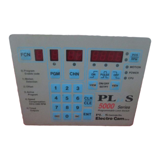
- Page 31 Keyboard Layout, Keys and Indicators setpoint programming operations. (The ON and OFF keys and LEDs are also used when programming the optional leading and trailing edge speed compensation feature). The VIEW keys allow the current On and Off setpoints of the currently selected channel to be displayed in sequence, one at a time.
-
Page 32: Output Setpoint Programming
Output Setpoint Programming CREATE SETPOINTS To create setpoints in output channel presently selected. On led lit, POS 1st Digit shown in 2 Digits shown in POS display blank POS display On at 30 degrees used as example. OFF led lit, POS 1st Digit shown in 2 Digits shown in POS display blinks... - Page 33 Master Level Programming, Standard Controls: FCN 0 Press: FCN 0 Programming at the Master Level FCN 0 Present Value / Choice (Master Program Enable Input MUST be energized) Feature being for displayed FCN 0 Programmed feature shown Function 0 allows specific features of the PLμS control to be FCN 0 Shown programmed when the Master Program Enable input is energized.
-
Page 34: Master Level Programming
Master Level Programming, Standard Controls: FCN 0 (continued) dd - Display Default (PS-51XX after 5/12/92) If FCN 0 Present display Auto, Spd, or PoS can be selected for the display default by not shown press: display default default (dd) shown pressing the Pulse key while “dd”... -
Page 35: Ru Rpm Display Update Frequency
ct, cS, cA - Communication Parameters If FCN 0 ct - comm type Present value for not shown press: cS - comm speed selected comm ct - communication type: Specifies the type of cA - comm Address item selected communication port being used by the PLμS control. It contains both an RS-232 and an RS-485 port. -
Page 36: Output Channel Access
Master Level Programming, Standard Controls: FCN 6 & FCN 7 Setting Output Channel Access FCN 6 - Operator Access (Master Program Enable Input MUST be energized) If FCN 6 Output Operator Enable status not shown press: shown for selected Channel This function selects which features can be adjusted at selected output channel... -
Page 37: Fcn 7 Motion Anding
FCN 7 - Motion ANDing of Output Channels If FCN 7 Present output Present Motion ANDing not shown press: channel status shown for output (Master Program Enable Input MUST be energized) selected selected This function selects which output channels will be ANDed with the Motion setpoints as programmed in FCN 1. -
Page 38: Fcn 8 Subdividing Outputs
Master Level Programming, PS-5XX4 Only: FCN 8 & FCN 9 Programming the Number of Output Groups FCN 8 - Subdividing Outputs into Groups If FCN 8 Present number of Present (Master Program Enable Input MUST be Energized) not shown press: outputs number of The outputs can be subdivided into as many as eight output... -
Page 39: Fcn 1 Motion Setpoints
Setup Level Programming, Standard Controls: FCN 1, FCN 2, FCN 3 FCN 1 - Motion Setpoints If FCN 1 Present RPM value for Lo or Hi (Setup or Master program enable must be active) not shown press: selected setpoint RPM setpoint shown selected Motion logic is active whenever the present RPM is between... - Page 40 Setup Level Programming, Standard Controls: FCN 1, FCN 2, FCN 3 If the hardware program select inputs are going to be used Viewing/Changing Program Number to select programs (they can be driven from a PLC or selector switch), it may be necessary to program the Program If FCN 3 Present Program not shown press:...
-
Page 41: Fcn 4 Speed Compensation, Standard
Setup Level Programming, Standard Controls: FCN 4 FCN 4 - Speed Compensation Present Output If FCN 4 Present Speed Comp (Setup or Master program enable must be active) Channel value for selected not shown press: Selected output channel shown Speed Compensation is the ability of the control to automatically advance an output's setpoints as the machine speeds up, thus compensating for the response of the device being controlled. -
Page 42: Fcn 5 Timed Outputs
Setup Level Programming, Standard Controls: FCN 4 & FCN 5 FCN 4 - Negative Speed Comp (continued) FCN 5 - Timed Outputs In order to activate Negative Speed Compensation, the (Setup or Master program enable must be active) corresponding channel must first be set equal to “0” speed Outputs can be turned off after a specified time duration, compensation in FCN 4, and then decremented by pressing instead of staying on until the off position setpoint is reached. -
Page 43: Section 5-Programming, Optional Features
Leading / Trailing Edge Speed Compensation: Option “-L” Selecting the Type of Speed Compensation FCN 0 Sc - Type of Speed Compensation (units with “L” option only) Present Speed comp type shown onE - Standard Speed Compensation: One value of If FCN 0 Sc - Speed not shown press:... -
Page 44: Fcn
Analog Output: Option “-A” FCN 1 Ao, Ah - Analog Output Signal Programming the Analog Offset (Units with "A" option only) If FCN 1 Present Analog offset Ao - Analog not shown press: in 1/4096ths of full offset The analog option allows PLµS controls to output an analog scale signal signal that is linearly proportional to the current machine RPM. -
Page 45: Gray Code Output ("-G")
Speed Compensated Gray Code Output: Option “-G” Gray Code Conversion Ladder Gray Code Position Output ( Units with the "G" Option) Plμs Controls with the Gray Code output option output eight bit Gray Code position information on the last eight outputs. The position output takes into account the control's Offset value. -
Page 46: Extra Program Storage ("-F")
Extra Program Storage: Option “-F” PS-5000 Series PLμS controls containing the “F” option Special Alternate Functions have been included in the “F” can store approximately four times as many output pulses option to report the total number of pulses that can be (approximately 4500 pulses) in permanent memory as stored, and how many are currently programmed. -
Page 47: Fcn 3 Program Number Changes
Extra Program Storage: Option “-F” (continued) FCN 3 - Program Number Changes Viewing / Changing Program Number The “F” option can store up to 992 unique programs in If FCN 3 Present Program memory. These program numbers can be created and not shown press: Program number shown... -
Page 48: Viewing/Editing Program
Extra Program Storage: Option “-F” (continued) Select Inactive Program Number to be Viewing/Editing Inactive Program Viewed/Edited Any inactive program can be viewed or edited from the PLuS keyboard while the current active program controls the machine. PGM LED off when Pn shown Selected program # inactive program... - Page 49 Phase Mark Registration: Option “-P” The “P” option (phase mark registration) dedicates two Output channels 14 and 15 are programmed individually so PLuS outputs—Channels 14 & 15—as registration they have the output duration and phase relationship required inspection windows for input to registration controls or by the registration control system.
-
Page 50: Input Information
Phase Mark Registration: Option “-P” (continued) Logic Terminal Strip (see pgs. 2-1 thru 2-3 for location) Terminals 6 thru 10 function the same as controllers without the “-P” Option. See pg. 3-1 for details. Input Information Registration Input Terminals Decrease Input (Terminal 3; normally Program Select 1) Input terminals 3, 4, and 5 have special registration functions The decrease input is a one-shot that... -
Page 51: Chn 80 Auto-Center Registration
Phase Mark Registration: Option “-P” (continued) CHN 80 - Auto-Center Registration Jog machine to position where Registration mark should be sensed. The gap between the output 14 and 15 pulses (registration Press POS/RPM key until POS LED OK area) can be automatically centered around the current is lit to view machine position machine position by accessing CHN 80. - Page 52 Phase Mark Registration: Option “-P” (continued) Automatic Reversal of Centering Logic Some registration control systems use the “Off” portion of used whenever the “On” duration of output 14 is greater the input signals as the registration correction windows. In than 180 degrees. In this “Off” logic mode, the registration these cases, outputs 14 and 15 will each be “On”...
-
Page 53: Output Grouping & Modes
Output Grouping and Modes Advantages of Grouping Outputs Outputs are assigned to the groups in sequential order. Therefore, Group 1 output(s) will start with the first available PS-5XX4 controls can be subdivided into as many as eight output (after the input modules on rack) and include the different output groups. - Page 54 Output Grouping and Modes I/O Configuration Examples Example #1: I/O Rack Configuration Example #1: On a nine I/O 5X24, establish three groups of outputs with four outputs in Group 1, two outputs in Group 2 and the remaining outputs (1) in Group 3. Group 2 and Group 3 both have a photo eye input associated with them Group 2 Input...
-
Page 55: Introduction
Mode Introduction - Mode 0 Operation Introduction to Modes Example Applications that Use Modes The use of modes allows PS-5XX4 controls to perform Web Converting Machines - Disposable diapers, medical output logic which goes beyond simple cam outputs. There pads, office folders, etc. Phase relationships between are five different modes (modes 0-4) which can be assigned machine sections can be adjusted manually using Mode 0 to output groups. - Page 56 Mode 1 Operation Details of Mode 1 - How to Program Mode 1 Operation Alter Position from Input Signal 1. Program FCN 8 and FCN 9 to correctly establish An output group operating in Mode 1 will have its outputs the output grouping and modes required for this enabled at all times.
- Page 57 Mode 1 Logic Flow Chart The flow chart to the right details how Mode 1 operates. The control’s response to any set of conditions can be determined by stepping through the flow chart blocks using those conditions when decision blocks are encountered. The flow chart shows when the group enable input is armed and disarmed.
- Page 58 Mode 2 Operation Details of Mode 2 - Alter Position and Enable Outputs How to Program Mode 2 Operation An output group operating in Mode 2 only has its outputs 1. Program FCN 8 and FCN 9 to correctly establish the enabled after an input signal has occurred.
- Page 59 Mode 2 Logic Flow Chart The control’s response to any set of conditions can be determined by stepping through the flow chart blocks using those conditions when decision blocks are encountered. The flow chart determines when the outputs are enabled and disabled by Mode 2 logic.
- Page 60 Mode 3 Operation Details of Mode 3 - AND Outputs with Input Signal How to Program Mode 3 Operation An output group operating in Mode 3 will have the same 1. Program FCN 8 and 9 to correctly establish the characteristics as a group operating in Mode 0, except that output grouping and modes required for this machine the corresponding enable input must be on to enable the...
- Page 61 Mode 3 Logic Flow Chart The flow chart to the right details how Mode 3 operates. The control’s response to any set of conditions can be determined by stepping through the flow chart blocks using those conditions when decision blocks are encountered. The flow chart determines when the outputs are enabled and disabled by Mode 3 logic.
- Page 62 Mode 4 Operation Details of Mode 4 - Input Signal Required for Output Cycle How to Program Mode 4 Operation An output group operating in Mode 4 only has its outputs 1. Program FCN 8 and FCN 9 to correctly establish enabled after an input signal has occurred within a specified the output grouping and modes required for this machine window of the machine cycle.
- Page 63 Mode 4 Logic Flow Chart The flow chart to the right details how Mode 4 operates. The control’s response to any set of conditions can be determined by stepping through the flow chart blocks using those conditions when decision blocks are encountered. The flow chart determines when the outputs are enabled and disabled by Mode 4 logic.
- Page 64 A problem with random access memory has been detected and the unit cannot function properly. Memory circuitry in the controller is not functioning properly. Solution: Control must be returned to factory for repair. Call Electro Cam first for return authorization and further information.
- Page 65 Error Messages (Continued) E4-Pro Programming Not Enabled A programming change was attempted when the corresponding level of programming access was not enabled. There are three levels of programming access. See page 4-1 for details. Solution: Press the CLR/CLE key to clear the flashing error message. Enable the appropriate level of programming access and make the necessary changes.
- Page 66 If one of the keyboard keys is on when the unit powers up, this message will be displayed. It can indicate that a key is shorted and always on. Solution: If “Pb Stuc” error message remains or occurs frequently on power up, call Electro Cam for further information.
- Page 67 Encoder Position Chart / 60 Pulse Disc for Encoder Based Controls This table shows how an encoder based PLuS control scales 256 increments into degrees. Each increment change is equal to exactly 1/256th of a revolution (approximately 1.4 degrees) even though the position displayed sometimes changes by 2 degrees for a 1 increment change in position (control skips 3s, 7s &...
-
Page 68: Alternate Functions
If a problem is found with the EEPROM the display will latch properly, the control will reset. Some versions may display up with the bad memory location address shown. Call “CrASH”. Press any key to restart the control. Electro Cam for further information if this happens. Appendix A-16... -
Page 69: Remote Display Installation
All of the programmable items in the display will be correctly set to auto; the display will automatically switch between set at Electro Cam before the display is shipped. This position and RPM at the toggle RPM value, regardless of information is stored in permanent memory in the display what the control's display is showing. -
Page 70: Specifications
Controller Specifications Electrical Maximum RPM: Encoder: 2000 RPM 24 VDC 20-30 VDC Resolver: Up to 3000 RPM 120 VAC 50/60 Hz: 108 - 132 VAC Depending on specific model & 240 VAC 50/60 Hz: 216 - 264 VAC optional features - Higher speed Power Consumption: 35 VA units available—consult factory Permanent Memory: EEPROM (no battery required) - Page 71 Transducer Specifications ENCODER(S) Operating Temp: 0° to 50°C (32° to 122°F) Storage Temp: -40° to 50°C (-40° to 122°F) Operating Humidity: 95% Relative non-condensing NEMA Rating: NEMA 12 (PS-4256, 4257) NEMA 4X (PS-4456, 4457) Max Cable Length: 1000 Ft. Enclosure Size: 6"W x 6"L x 4.25"H Mounting Holes (4): 5/16"...
- Page 72 AC/DC Output Module Specifications Reed Relays: EC-ORR5 (Standard) AC Outputs: EC-OAC5A-11 (Standard) EC-OAC240-3 (Slimline) Output Type: N/O Reed Relay Contacts Contact Rating: 10VA maximum Load Voltage: 24 V minimum (DC resistive load) 280 V maximum Switching Volts: 0 V to 200 V, DC or peak AC Load Current: 30 mA minimum...
- Page 73 Analog Output Module Specifications 0-10 VDC: EC-ANLG-010V (Standard) EC-SANL-010V (Slimline) Resolution: 12 Bits (4096 increments) Output Voltage: 0-10 VDC Output Current: 140 mA DC maximum Accuracy: +/- 0.3% full scale @ 25°C (77°F) 4-20 mA: EC-ANLG-420M (Standard) EC-SANL-420M (Slimline) Resolution: 12 Bits (4096 increments) Output Current: 4 mA DC to 20 mA DC...
- Page 74 Input Module Specifications DC Inputs: EC-IDC5 (Standard) EC-IDC032 (Slimline) Input Voltage: 10-32 VDC Input Current: 34 mA maximum (@32 VDC input) Output Supply Voltage: 4.5 VDC to 6 VDC 5 VDC nominal Output Supply Current: 18 mA DC maximum @ 5 VDC Turn On Time: 5 ms maximum Turn Off Time:...
- Page 75 Transistor Output Specifications Sinking Transistor Outputs (PS-5X11, N08 and N16) Output Type: Current Sinking (NPN) Output Voltage: 5 - 30 VDC Output Current: 50 mA cont. maximum Input Voltage: 5 - 30 VDC Sourcing Transistor Outputs (PS-5X11, P08 and P16) Output Type: Current Sourcing (PNP) Output Voltage:...
-
Page 76: Index
Index +12 VDC Output (Logic Terminal Strip) ..3-1 Communications ......4-6 60 Pulse Disc cA, Communication Address . - Page 77 Index FCN 0 Fuses 12 VDC Power Supply (Logic Terminal Strip) . . . 3-1 All Controllers Direction of Increasing Rotation (dr) ..4-4 Controller Input Power (1/2 Amp) ..2-1, 2-2, 2-3 Logic Terminal Strip (12 VDC Power Supply) .
- Page 78 Index Motion ANDing (FCN 7) ..... . 4-8 Program Select Inputs ......3-1 Motion Detection PULSE Key .
- Page 79 Index “tr” (FCN 0) ....... . 4-5 Transistor Output Replacement ......3-6 Specifications .
- Page 81 800-228-5487 (U.S.A. and Canada) • Web Site: www.electrocam.com • email: ecam@electrocam.com PRINTED IN U.S.A 252 01/06...