Table of Contents
Advertisement
Advertisement
Table of Contents
Troubleshooting

Related Manuals for Emerson Liebert GXT4-700RT230


Summary of Contents for Emerson Liebert GXT4-700RT230
- Page 1 GXT4 ® ™ Liebert User Manual – 700VA 3000VA (230V)
-
Page 3: Important Safety Precautions
This UPS contains no user-serviceable parts except the internal battery pack. Do not continue to use the UPS if the front panel indications are not in accordance with these operating instructions or if the UPS performance alters in use. Refer all faults to your local dealer, Emerson Network Power representative or Emerson Network Power Channel Support. -
Page 4: Battery Safety Notes
The Liebert GXT4 UPS series complies with the requirements of EMC Directive 2004/108/EC and the published technical standards. Continued compliance requires installation in accordance with these instructions and use of accessories approved by Emerson. Information For The Protection Of The Environment UPS Servicing: UPS makes use of components dangerous for the environment (electronic cards, electronic components). -
Page 5: Glossary Of Symbols
Glossary Of Symbols Risk of electrical shock Indicates caution followed by important instructions AC input AC output Requests the user to consult the manual Indicates the unit contains a valve-regulated lead acid battery Recycle DC voltage Equipment grounding conductor Bonded to ground AC voltage WEEE... -
Page 7: Table Of Contents
Contents Chapter 1 Product Description ............................1 1.1 Features ................................1 1.2 Available Models ..............................1 1.3 Appearance And Components ..........................2 1.3.1 Front Panel and Controls ........................... 2 1.3.2 Rear Panel Features ..........................2 ... - Page 8 4.5 Shut Down The Liebert GXT4 ..........................25 4.6 Disconnecting Input Power From The Liebert GXT4 ................... 26 Chapter 5 Communication ..............................27 5.1 Liebert IntelliSlot Port Communication ........................ 27 5.2 USB Port Communication ........................... 27 ...
-
Page 9: Chapter 1 Product Description
Chapter 1 Product Description Chapter 1 Product Description The Liebert GXT4 UPS is a compact, online uninterruptible power system that continuously conditions and regulates its output voltage. The UPS is designed to supply microcomputers and other sensitive equipment with clean sine wave input power. -
Page 10: Appearance And Components
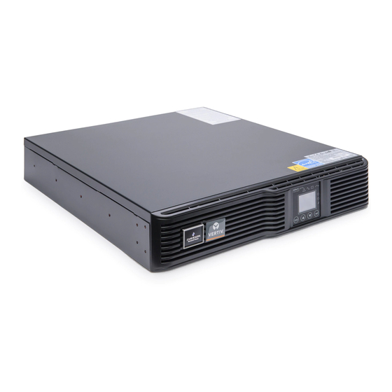
Chapter 1 Product Description 1.3 Appearance And Components The Liebert GXT4 rack/tower models in various power ratings have the same general appearance, controls and features (see Figure 1-1). The various rack/tower models differ largely in the type of receptacles each has. 1.3.1 Front Panel and Controls The front panel of the Liebert GXT4 UPS is shown in Figure 1-1. -
Page 11: Operating Principle
Chapter 1 Product Description 1.4 Operating Principle The operating principle of the UPS is illustrated in Figure 1-4. Input Output Dynamic Bypass TVSS & EMI/RFI Rectifier/PFC Inverter Filters DC-to-DC Converter Battery Charger Battery L2/N L2/N Figure 1-4 Operating principle diagram The UPS is composed of utility input, TVSS and EMI/RFI filters, rectifier/PFC, inverter, battery charger, DC-to-DC converter, battery, dynamic bypass and UPS output. -
Page 12: Operating Mode
Chapter 1 Product Description Battery The Liebert GXT4 UPS uses valve-regulated, nonspillable, lead acid batteries. To maintain the battery design life, operate the Liebert GXT4 UPS in an ambient temperature of 32°F to 77°F (0°C to 25°C). Optional external battery cabinets are available to extend battery run time. Dynamic bypass The Liebert GXT4 UPS provides an alternate path for utility power to the connected loads in the unlikely event of a UPS malfunction. - Page 13 Chapter 1 Product Description Battery Recharge mode Once utility power is applied to the Liebert GXT4, the battery charger begins charging the batteries. Frequency Converter mode All models of the Liebert GXT4 are capable of frequency conversion. Frequency Conversion mode can be selected using the configuration program or LCD.
-
Page 14: Chapter 2 Installation
1. Inspect the UPS for shipping damage. If any shipping damage is found, report it to the carrier and your local dealer or your Emerson representative immediately. 2. Check the accessories included in packaging list. If there is any discrepancy, contact your local dealer or your Emerson representative immediately. -
Page 15: Installation Clearances
Chapter 2 Installation 2. Place it in an area of unrestricted airflow around the unit, away from water, flammable liquids, gases, corrosives, and conductive contaminants. Avoid direct sunlight. Note Operating the Liebert GXT4 UPS in temperatures above 77°F (25°C) reduces battery life. 2.3.2 Installation Clearances Maintain at least 4 inches (100mm) clearance in the front and rear of the Liebert GXT4. -
Page 16: Rack Installation
Chapter 2 Installation 2) Pull the operation and display panel gently, rotate it 90 degrees clockwise and snap it back into position, as shown in Figure 2-4. Operation and display panel 90-degree rotation clockwise Figure 2-4 Rotate the operation and display panel 3) Pull the logo on the front plastic bezel cover gently, rotate it 90 degrees clockwise and snap it back into position. - Page 17 Chapter 2 Installation Note B1 includes inner member, front and rear members. They are interchangeable between left-hand or right-hand. 2. Remove inner member of each B1 by extending it to its outermost position, depressing the retaining latch and then pulling out the inner member from B1, as shown in Figure 2-7.
- Page 18 Chapter 2 Installation Front vertical pole Front member Rear member S2 (2 pcs) S2 (2 pcs) A amplified B amplified Figure 2-9 Installing front member of each B1 6. Fasten rear member and front member together using four A1 and four M4 nuts (M4 nuts have been factory-installed on the rear member) for each B1, as shown in Figure 2-10.
-
Page 19: Cable Connection
3. The input cable is intended to serve as the disconnect device. The socket-outlet must be installed near the equipment and must be easily accessible. 4. Emerson recommends installing an upstream circuit breaker of the same series as the Liebert GXT4’s input circuit breaker. The specification of input circuit breaker on the UPS rear panel is given in Table 2-1. -
Page 20: Connecting Battery Cable
Chapter 2 Installation Table 2-1 Specification of input circuit breaker Model Rated circuit breaker GXT4-700RT230 GXT4-1000RT230 GXT4-1500RT230 GXT4-2000RT230 GXT4-3000RT230 GXT4-700RT230E GXT4-1000RT230E GXT4-1500RT230E GXT4-2000RT230E GXT4-3000RT230E 1. Plug all loads into the output receptacles on the rear panel of the Liebert GXT4. ... -
Page 21: Connecting Communication Cables
Chapter 2 Installation 2.5.3 Connecting Communication Cables Communication cable connection includes: USB communication cable, RS232 communication cable and optional card cables. Connecting USB communication cable 1. Take the USB communication cable out of the accessories box. 2. Insert one end of the USB communication cable to the USB port on the rear panel of the Liebert GXT4 (see Figures 1-2 and 1-4). -
Page 22: Chapter 3 Operation And Display Panel
Chapter 3 Operation And Display Panel Chapter 3 Operation And Display Panel This chapter describes the operation and display panel of the Liebert GXT4, including LED indicators, control buttons and LCD display panel. The operation and display panel is on the front panel of the Liebert GXT4 (see Figure 1-1), which provides four control buttons, seven LED indicators and a LCD display panel, as shown in Figure 3-1. -
Page 23: Lcd Display Panel
The operation and display panel provides a LCD display panel, enabling you to view the UPS status and change the UPS settings. 3.3.1 Startup Screen When the UPS is starting up, the UPS begins self-testing, and then the LCD display panel will display EMERSON icon for about 10s, as shown in Figure 3-2. Figure 3-2 Startup screen 3.3.2 ON Screen... -
Page 24: Default Screen
Chapter 3 Operation And Display Panel 3.3.3 Default Screen Press any button in the ‘STATTUP SUCCESSFULLY’ screen to enter the default interface, as shown in Figure 3-5. Figure 3-5 Default screen In the default screen, the LCD display panel will display the UPS model, operation mode (ONLINE, GREEN, GREEN AUTO, and BYPASS), output parameters, input parameters, battery capacity and load percentage. - Page 25 Chapter 3 Operation And Display Panel 1 UPS 2 BATTERY 3 OPERATION MODE 4 OUTLET1 5 OUTLET2 6 LCD 7 FACTORY DEFAULT Figure 3-8 CONFIGURATION screen In the CONFIGURATION screen, press the UP or DOWN button to move the cursor to the required item, and press the ENTER button to enter its submenu or set its parameter.
- Page 26 Chapter 3 Operation And Display Panel Press the UP or DOWN button to move the cursor to the required item, and press the ENTER button to confirm the settings. 4. OUTLET1 screen Select Main Menu -> 2 CONFIGURATION -> 4 OUTLET1 to enter the OUTLET1 screen. This menu has two submenus, as shown in Figure 3-12.
- Page 27 1) Select ‘1 LANGUAGE’ and press the ENTER button to enter the LANGUAGE screen, as shown in Figure 3-17. Figure 3-17 LANGUAGE screen 2) Select ‘2 COLOR’ and press the ENTER button to enter the COLOR screen, as shown in Figure 3-18. EMERSON EMERSON EMERSON...
- Page 28 Chapter 3 Operation And Display Panel Figure 3-20 CONTROL screen In the CONTROL screen, press the UP or DOWN button to move the cursor to the required item, and press the ENTER button to enter its submenu. 1. TURN ON & OFF screen Select Main Menu ->...
- Page 29 Chapter 3 Operation And Display Panel 1. Select Main Menu -> 4 LOG -> 1 EVENT LOG to enter the EVENT LOG screen, as shown in Figure 3-25. Figure 3-25 EVENT LOG screen Select ‘1 ALL’ and all logs will be displayed, as shown in Figure 3-26. A maximum of one log can be displayed in a screen, displaying the nature and time of the event.
-
Page 30: Prompt List
Chapter 3 Operation And Display Panel Figure 3-29 Menu structure 3.3.5 Prompt List A prompt screen is displayed during the operation of the system to alert you to certain conditions and/or to require your confirmation of a command or other operation. The prompts and meanings are given in Table 3-3. Table 3-3 Prompts and meanings Prompt Meanings... -
Page 31: Warning List
Chapter 3 Operation And Display Panel Prompt Meanings The shutdown command sent through Multilink or SNMP card to the UPS shutdown process had been cancelled UPS is cancelled UPS reboot Reboot the UPS through Multilink or SNMP card UPS switch to Green mode The UPS transfers back to Green mode, saving more electricity When the input utility power satisfies the condition of Auto Green UPS switch to Auto Green mode... - Page 32 Chapter 3 Operation And Display Panel Fault Description Over-temperature occurs to the UPS and the UPS will transfer to UPS Over-temperature Bypass mode Charger Out of Order The charger is faulty Fan Out of Order At least one fan is faulty DC Bus Discharge Fail DCDC failure occurs If a fault occurs, the UPS automatically switches to Bypass mode.
-
Page 33: Chapter 4 Operating Instruction
Chapter 4 Operating Instruction Chapter 4 Operating Instruction This section describes checks before starting the UPS, how to start the UPS, manual battery test, manual bypass, shutting down the UPS and disconnecting the utility power from the UPS. Note The Liebert GXT4’s battery has been fully charged before delivery, but some charge will be lost during storage and shipping. -
Page 34: Disconnecting Input Power From The Liebert Gxt4
Chapter 4 Operating Instruction 4.6 Disconnecting Input Power From The Liebert GXT4 1. Once the UPS has been shut down as detailed in 4.5 Shut Down The Liebert GXT4, disconnect the input cable plug. 2. Wait 30 seconds and verify that all indicators have turned Off and the fan has stopped, this indicates that the power-off is complete. -
Page 35: Chapter 5 Communication
UPS over a network. For more information about the Liebert IntelliSlot SNMP Card, Liebert IntelliSlot Web Card and Liebert MultiLink license kits, visit the Liebert Web site (www.liebert.com) or contact your local Emerson representative. 5.2 USB Port Communication The standard B-type USB port is used to connect the UPS and network server or other computer system using Liebert MultiLink. -
Page 36: Rs232 Port Communication
Chapter 5 Communication Select one of multiple output voltages to match various voltages, see Table 5-1. Table 5-1 Output voltage option UPS model Factory default, Vac Output voltage option, Vac GXT4-700RT230 ~ GXT4-3000RT230 220/230/240 GXT4-700RT230E ~ GXT4-3000RT230E 220/230/240 Warning The output voltage settings cannot be changed while the UPS is on and powering connected loads. -
Page 37: Battery Mode Shutdown
Chapter 5 Communication Warning When the Auto-Enable output option is selected and the UPS output is disabled using Pin1 and Pin2, the Liebert GXT4’s output can turn on automatically without warning if the Pin1 and Pin2 connection is changed. 5.4.2 Battery Mode Shutdown Battery Mode Shutdown permits shutting down the UPS by turning off the rectifier, inverter and bypass so that there is no power to the load when the UPS is On Battery. -
Page 38: Chapter 6 Maintenance
3. Do not lay tools or other metal objects on the batteries. 4. If the battery kit is damaged in any way or shows signs of leakage, contact your local Emerson representative immediately. 5. Do not dispose of batteries in a fire. The batteries may explode. - Page 39 If so, proceed with Step 7; if they are different, stop and contact your local Emerson representative, or Emerson Channel Support. 7. Line up and slide in the new internal battery pack.
-
Page 40: Battery Charging
Liebert GXT4 charges the batteries continuously when it is connected to the utility input power. If the Liebert GXT4 will be stored for a long time, Emerson recommends connecting the UPS to input power for at least 24 hours every four to six months to ensure full recharge of the batteries. -
Page 41: Chapter 7 Troubleshooting
Chapter 7 Troubleshooting Chapter 7 Troubleshooting This section indicates various UPS symptoms a user may encounter and troubleshooting steps in the event the UPS develops a problem. Use the following information to determine whether external factors caused the problem and how to remedy the situation. -
Page 42: Troubleshooting
Bypass reminder 1-second beep every 1 minutes 7.2 Troubleshooting If any technical problems should occur, check the following before contacting Emerson technical support: 1. Is the utility voltage present at the UPS input? 2. Have the circuit breakers tripped? 3. Has the UPS startup procedure been followed correctly? When contacting Emerson technical support, have the following information to hand: ... -
Page 43: Chapter 8 Battery Cabinet
Chapter 8 Battery Cabinet Chapter 8 Battery Cabinet Optional battery cabinets are available for the Liebert GXT4. The battery connectors and input breaker are on the battery cabinet’s rear panel, as shown in Figure 8-1. For battery cabinet specifications, refer to Table 9-3. The Liebert GXT4 may be equipped with a maximum of six extension battery packs. -
Page 44: Chapter 9 Specifications
Chapter 9 Specifications Chapter 9 Specifications The specifications of 700VA ~ 3000VA are listed in Table 9-1 and Table 9-2. Table 9-1 Specifications of GXT4-700RT230 ~ GXT4-1000RT230 UPS (included the E model) Product model Parameters GXT4-700RT230 & GXT4-700RT230E GXT4-1000RT230 & (700VA/630W) GXT4-1000RT230E (1000VA/900W) Dimensions, D... - Page 45 Chapter 9 Specifications Table 9-2 Specifications of GXT4-1500RT230 ~ GXT4-3000RT230 UPS (included the E model) Product model GXT4-1500RT230 & GXT4-2000RT230 & GXT4-3000RT230 & Parameters GXT4-1500RT230E GXT4-2000RT230E GXT4-3000RT230E (1500VA/1350W) (2000VA/1800W) (3000VA/2700W) 23.7 × 16.9 × 3.4 Dimensions, D Unit 19.7 × 16.9 × 3.4 (497 × 430 × 85) (602 ×...
- Page 46 Chapter 9 Specifications Table 9-3 Battery cabinet specifications Model Number Parameter GXT4-48VBATT GXT4-48VBATTE GXT4-72VBATT GXT4-72VBATTE GXT4-700RT230,GXT4-700RT230E GXT4-1000RT230,GXT4-1000RT230E Used UPS model GXT4-3000RT230,GXT4-3000RT230E GXT4-1500RT230,GXT4-1500RT230E GXT4-2000RT230,GXT4-2000RT230E Dimensions, D Unit 19.7 × 16.9 × 3.3 (497 × 430 × 85) 23.7 × 16.9 × 3.3 (602 × 430 × 85) ×...
- Page 47 Chapter 9 Specifications 230Vac RT Models(Include E Models) Number of batteries Load 700VA 1000VA 1500VA 2000VA 3000VA Internal battery + 2 external battery cabinets 100% Internal battery + 3 external battery cabinets 100% Internal battery + 4 external battery cabinets 100% Liebert GXT4 UPS 700VA ~ 3000VA (230V) User Manual...
-
Page 48: Chapter 10 Product Warranty Registration
To register for warranty protection, visit the Quick Links section of the Liebert Web site at: http://www.liebert.com Click on Product Warranty Registration and fill in the form. If you have any questions, contact Emerson Channel Support at: North America: 800-222-5877 Outside North America: 00-800-1155-4499... - Page 50 Network Power service technicians. While every precaution has been taken to ensure the accuracy and completeness of this literature, Emerson Network Power assumes no responsibility and disclaims all liability for damages resulting from use of this information or for any errors or omissions.