


8 views in the last 24 hours
Price: $91.25
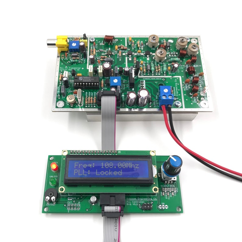
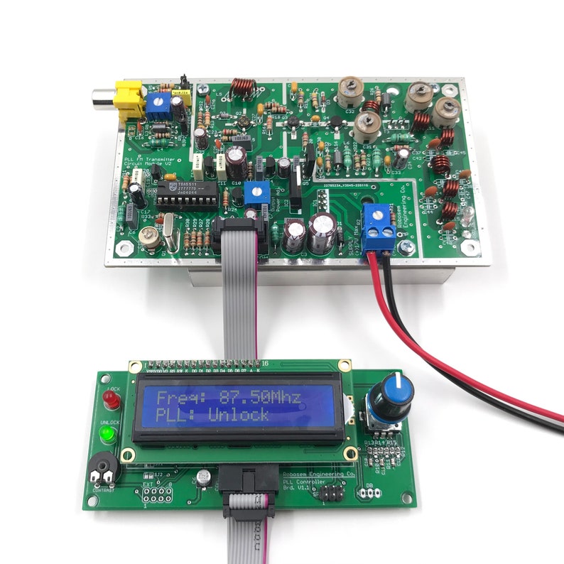
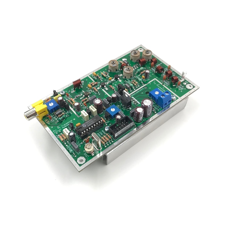
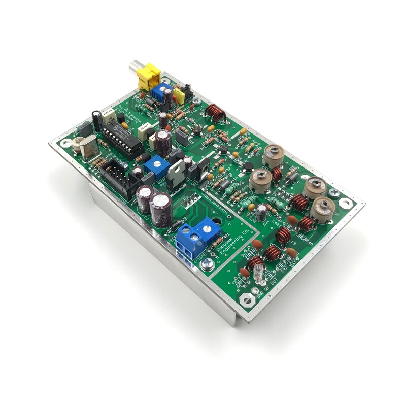
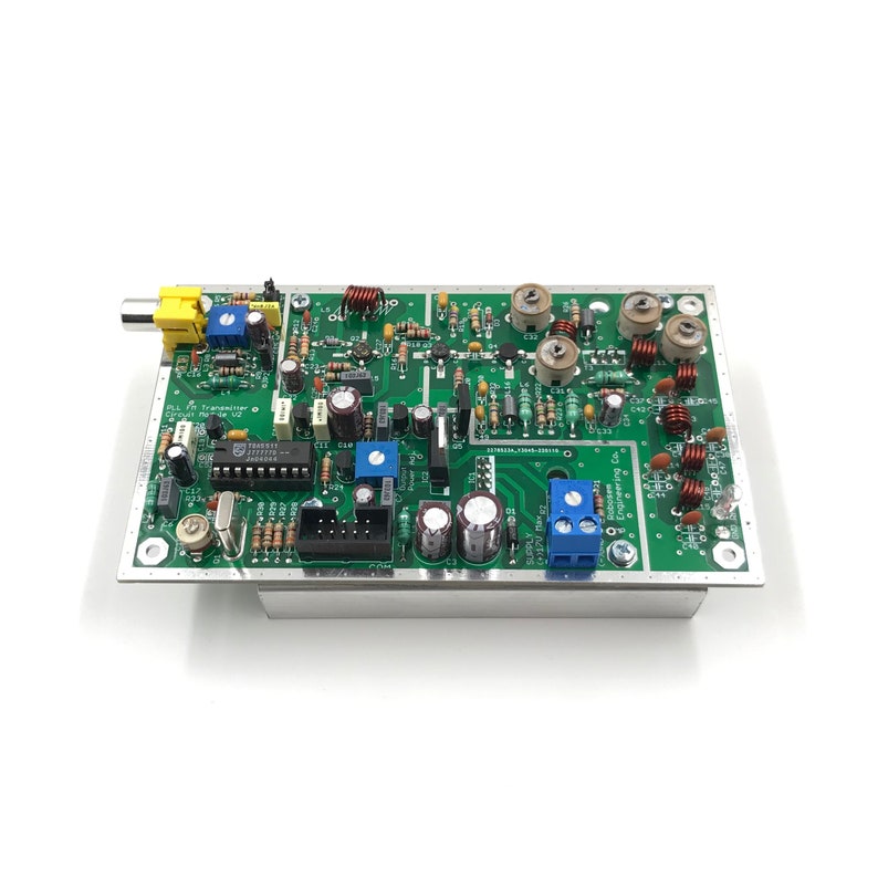
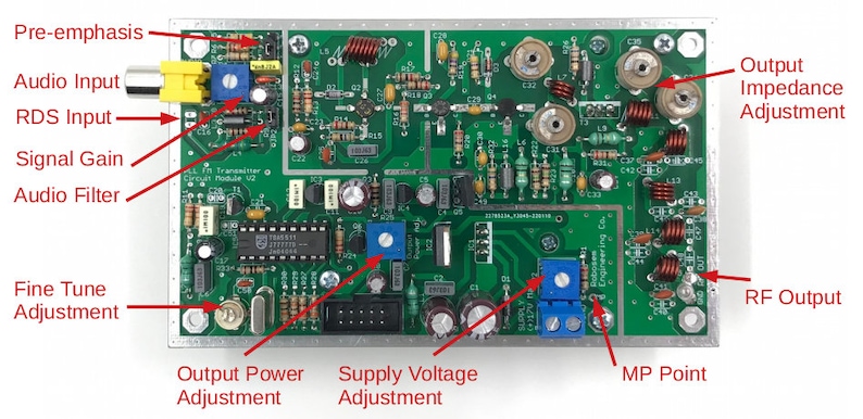
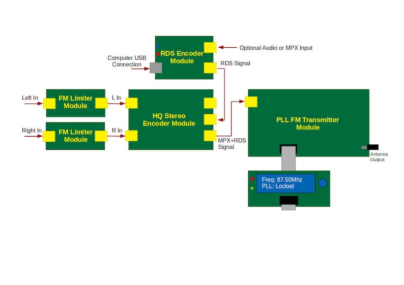
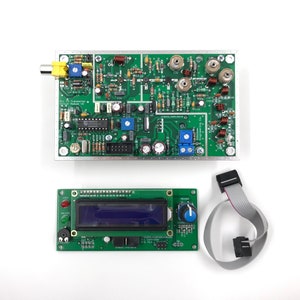
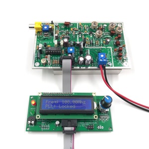
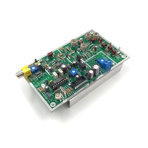
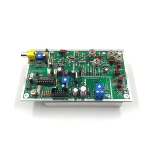
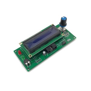
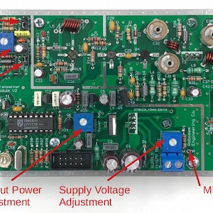
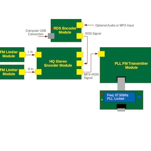
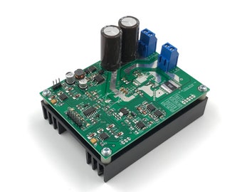
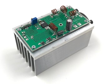
PLL Fm Transmitter Circuit Module 7W 87.5-108 Mhz for Fm Broadcasting Station Adjustable Frequency 7 Watt VHF Radio Band RF Amplifier
Your order should arrive by this date if you buy today. To calculate an estimated delivery date you can count on, we look at things like the carrier's latest transit times, the seller's processing time and shipping history, and where the order is shipping to and from.
Returns & exchanges accepted
You can only make an offer when buying a single item
-
Order today to get by May 3-8
Your order should arrive by this date if you buy today. To calculate an estimated delivery date you can count on, we look at things like the carrier's latest transit times, the seller's processing time and shipping history, and where the order is shipping to and from.
-
Returns & exchanges accepted within 14 days
Buyers are responsible for return shipping costs. If the item is not returned in its original condition, the buyer is responsible for any loss in value.
-
Cost to ship: $8.27
There was a problem calculating your shipping. Please try again.
Etsy Purchase Protection: Shop confidently on Etsy knowing if something goes wrong with an order, we've got your back for all eligible purchases — see program terms

27 reviews
5 out of 5 starsAbsolutely perfect customer experience is what I received whilst buying a transmitter and amplifier. Robosem confirmed , reassured, dispatched, delivered, packaged and most importantly built the amp and transmitter impeccably. Would give more stars if possible. I no longer need to shop around for my next rig. If your looking for an FM Transmitter and the like then stop looking and get in touch with the Robosem team here. Thanks to the Robosem team. 👍🏻🔉🔉🔉🔉🔉🔉
Nik Powell Apr 7, 2024
Recieved the 7 watt exciter a lot quicker than expected. It is a beautifully built unit, it is almost a shame to have to hide it inside a box. Once hooked up and turned on, it was very easy to make the adjustments needed for the frequency I was operating on. After setting the MP power to 13.9 volts, the output was 5 1/2 watts into an antenna with a 1.2 vswr. The transistors and heat sink ran warm, but never actually got hot, so that was good as well. I am planning on purchasing the stereo encoder, and possibly the 100 watt amp sometime in the future. This is a very well built professional unit, having a very clean output, without the harmonic hash you get from the Chinese plug and play units flooding the market today. Oh, almost forgot, the audio quality was excellent as well
George W Kibler Nov 28, 2023
Photos from reviews
More from this shop
![RF Amplifier 8-2000 MHz, Gain = 20 dB, P = +20 dBm MRFA89 MMIC SOT-89 [Gold plated Board]](https://i.etsystatic.com/13010199/c/3000/2384/0/307/il/447ab2/2976260030/il_340x270.2976260030_61ir.jpg)
![TAFM2833 144 MHz RF Transmitter [with Antenna]](https://i.etsystatic.com/16326921/c/3000/2384/0/230/il/6ec6cf/2332033045/il_340x270.2332033045_dnng.jpg)
Disclaimer: Etsy assumes no responsibility for the accuracy, labeling, or content of sellers' listings and products. Electrical or electronic products may pose a risk of fire or electrocution. Vintage, handmade, refurbished, or modified electrical or electronic products may not meet current safety standards and may not be in safe working order. Inspect carefully before use and message the seller if you have concerns relating to the product. Do not use a vintage electrical or electronic item if its safety cannot be verified. To reduce the risk of fire, never leave vintage electrical or electronic products plugged in unattended. See Etsy's Terms of Use for more information.
