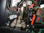
Desparately seeking Xantia blower mod diagram

...

ps there must be other issues since it would only run full speed briefly and no alteration care of the auto/ max slider control. Who knows! It’s a right little monkey.

Have recently taken a Series II wagon back from my son which has exactly that problem. My son says it's the slider control that is cactus and I have no reason to doubt him. We think it's essentially stuck on Auto

To test if it's stuck on auto, try moving thermostat to an extreme (ie coldest setting if car has been sitting in the sun), then listen carefully to see if the fan runs faster - mine definitely does, but it is easier to tell if the carpet trim that covers the fan has been removed first.

Cheers

Alec
 
Steven,

Here are a couple more circuit diagrams. One is of the AC system that might be a bit more readable than the usual style circuit and the other is a diagram of the circuit in the blower module. It has two sections, the 2 x PNP power transistors that regulate the motor speed and another circuit that switches in the relay (in the blower regulator) to bypass the PNP transistors tomake the motor go at full speed.

So if a module will only go at full speed, there is likely a problem with the power transistors. I have seen them replaced with 2N2955 type power transistors.

Cheers, Ken
 

Attachments

  • Blower control module.JPG
    Blower control module.JPG
    88.6 KB · Views: 721
  • AC french circuit diagram.jpg
    AC french circuit diagram.jpg
    101.8 KB · Views: 845
Here are some pictures of the blower motor module. It would be best to find a friend with some electronics skills to troubleshoot and repair this module.

The lead connector on one of my blower motors has become so heat affected that I have had to replace it with new wires that are directly soldered to the circuit board the holds the carbon brush holders and then connect back to the control module. Both my motors have had their brushes replaced many years ago - they must be coming up to need their second set of brushes soon.

Cheers, Ken
 

Attachments

  • Under blower transistors rest of circuit.JPG
    Under blower transistors rest of circuit.JPG
    90.3 KB · Views: 372
  • Blower Transistors 2.JPG
    Blower Transistors 2.JPG
    94.7 KB · Views: 301
  • blower transistors.JPG
    blower transistors.JPG
    92.2 KB · Views: 570
Last edited:
thanks Ken, I replaced the entire module and brushes awhile ago thinking that the blower itself was the root of the problem and doing this as a potential fix. Getting the fan off to get to them is tricky as it is a press fit and very difficult to prise off without breaking. Someone has tinkered with this before as the plastic that holds the 3 screws to fix the blower in place are cracked. I did test the blower by putting power on the 4 pin which I assume is the connection for the speeds, only getting power on second pin. Also only point where power in must go. I have only had it on a few times since so roasting it since seems unlikely. I am going to tinker with it today and hopefully unravel more of the mystery, thought I’d see if I can get it going off a battery independently but plugged into the rest of it.
 
Last edited:
this is really pissing me off! Looking at the photos I’m just confused and do not understand what to do.
The photo with the two red wires coming out of the ignition going to the brown plug that are cut and spaded onto the relay (which connections on relay?)

The other two? one an input yo 30 and the other an earth (What relay connection?)
plus the power going in, does that come from the orange wire on grey plug connection?
And what happens to that wire if separated from ignition?

this photo is from the wiring relay thread John JBN put up many moons ago.

AAF6794D-F5E2-4D4D-9EC0-15E75F62C451.jpg

I dug this up too after a quick hunt xantia pulseur relai, its still not clear to me what to do though : )

D26F8F8A-E725-4FD3-975E-BE9A45E47010.jpeg

how does this sound? My interpretation of this deplorable abhoration.


cut both red wires on ignition side
connect red live wire (originally joins brown wire join “1” on brown plug) at 86 on relay.
connect red wire ( originally joins orange wire join “2” on brown plug) at 87 on relay.
cut orange from ignition ( originally joins at “2” on grey plug and connect to 30 on relay.
Earth from 85.
 
Last edited:
Hi Stephen,

Let's go with the circuit you have found.

Is the blower switch on your ignition switch working OK? If so you can use the return from the switch to power the relay coil on pin 86. If not you will need to find another ignition switched lead to power the relay (maybe the cigarette lighter or radio feed). Connect the other side of the coil 85 to chassis. Don't cut the lead to the ignition switch from the battery, just remove some insulation and solder another thick lead to run from this to terminal 30. Then connect the cur lead that goes to F20 and the blower module/motor to pin 87.

Is that easier to follow.

Cheers Ken
 
i don’t think the switch is working now Ken, but then again?…I had the blower briefly working wired up in the car on two occasions after removing it and testing on the bench with a transformer. In the car when I connected it all back again I only ran it for a about ten seconds as it was going full tilt and I though it might have a hernia or cause grief somewhere else. Since that I disconnected and have just driven. I made up a juicy earth lead straight to blower then onto a bolt assumed on chassis close by which I thought might provide better earth but blower wouldn’t run anyway, so not sure yet even if that earth is correct.
Am I wrong thinking the relay is to bypass the ignition blower switch as this is one of the possible issues that cause them to die in the first place?

the penny dropped on that photo with the orange lead on grey plug number one,the power is as you keep pointing out T ing off the orange on the ignition side.
 
Last edited:
Yes that is exactly what the relay is for - to take all the load off these switch contacts if they are not completely burned out yet. The idea is to fit relay 8048 from the Series 2 Xantia circuit that Seasink originally posted.

Cheers, Ken
 
I think I get it now finally, just have t research how to access the fuse box.
while I’m raving on where does the comfort relay live?

punting it affects operation of climate control?

guessing that could also be worth investigating connections, damage!

A bit more googling came up with the speed control resistor going bung on Pugs, so will endeavour to find where the xantia one lives, as that could be snafu too, I imagine it lives tucked up somewhere impossible to reach behind the radio I guess :[

just removed the pollen filter and was not very impressed. gave it a wash but I’ll probably get a replacement.
 

Attachments

  • A55759A6-DC35-449A-AA4F-6747C96FB0B9.jpg
    A55759A6-DC35-449A-AA4F-6747C96FB0B9.jpg
    91.1 KB · Views: 331
Last edited:
The picture you have found is the Textron box which is the early BSI that only exists in the Series 2 Xantia. Your car should not have one of these.

The blower module (it is much more complicated than a resistor these days) is mounted in the plastic housing that the blower motor fits in.

The soft/firm hydractive solenoids are directly controlled by the Suspension Computer that sits beside the engine ECU right up front. I would leave it as it is until you have some climate control working.

Cheers, Ken
 
Thankyou again Ken, I had a quick demented search for the resistor which is described in Haynes to be in the base of the heater and nup nothing there, (since learnt only on non a/c versions) there was a black box tucked up the side though on the right side, I had a quick look at the circuit bosrd in it and nothing looked fried.
 
Last edited:
Oh well fitted relay and not a sausage. Mood altering experience. Cranky.

Maybe the transistor thing in the blower motor shert itself. Will have to remove and inspect.

Its got me stumped.

Back to the drawing board.
 
Is the new relay clicking in when the ignition is turned on? Are you getting 12 volts to the main power feed to the module/motor assembly? Is F20 good?.

Is there another relay on the blower module clicking in when the fan speed is set to maximum?

Cheers, Ken
 
tbc Ken sigh!

ps yes hearing relay cick on.

power available at fan blower connection however the brown plug to motor is another mystery.

Testing the motor with a 12V source outside the car I found the positive was on the second pin of the fourpin brown connector. However the plug has the red power on the first pin, orange then black then white. So I just flipped the red over to the orange pin and it works albeit full speed in the car.

but I guess the orange and white wire are to do with speeds and climate control so no aircon!

replaced wires as should be and getting about 3 or 4 volts on orange wire which I think emanates from climate control, had a look at climate circuit board with magnifying glass and couldn’t spot any obvious damage. Looking at replacing this with another to test. Wondering if temp sensor on mirror has effect on system operation as this is not connected I don’ think, replacing mirror with second hand one as I busted mine on gate the other day!
 
Last edited:
thankyou Gman, this is the definitive diagram. Hopefully others who encounter the problem will see it. I’m still trying to work out what is prohibiting my aircon functioning.
 
Hi
This is the INFO- RAPID from Citroen,hope it helps.
9842d4e1023ba6fbd7a0851b3e125e23.jpg
0b5f40ca89a62c5c369f39d77ff19675.jpg


Sent from my iPhone using aussiefrogs

I have TWO relays to the blower motor. The first was in the steering housing and somewhere along the line someone (maybe me) inserted another just before the blower motor.

Reading the above diagram, it seems the problem manifests itself if the blower fan is in either AUTO or Max when the ignition is operated. My problem is with the blower, which has had a new electronics pack added to it BUT it won't switch off (regardless of where the slide switch is positioned) and the fan speed is constant. I expect the problem is with the resistance, but reading the Haynes manual it says this is a difficult task as it requires the removal of the fascia panel. I'll pass on that.

A check list of the Xantia at 200,000kms is:

1. Engine works

2. Gearbox works

3. Steering works

4. Brakes work

5. All lights work

Compared to the T-Model Ford, I am quids ahead.

I told my wife (whose car this is) not to worry. On a hot day, push the aircon button otherwise leave it off (don't rely on the LED in the switch as it is too dull to see, just check the temperature from the vents). If the windscreen starts to mist on a rainy day, switch on the aircon. If you don't like a constant breeze from the vents, point them somewhere else or close them.

I think the zenith in Citroen cabin ventilation was reached with the 2CV and its swinging windows. When they tried to electrify that it buggered up, certainly in the BX and Xantia.

John
 
Top