SOILS & FOUNDATIONS Designing for Resilience 8 Engineers Examine Ukraine Damage 11 Creating Land in Port Canaveral 37 AWARDS STRUCTURAL ENGINEERING STRUCTURE NCSEA | CASE | SEI DECEMBER 2022


Verify your project design with full-scale, application-specific testing.

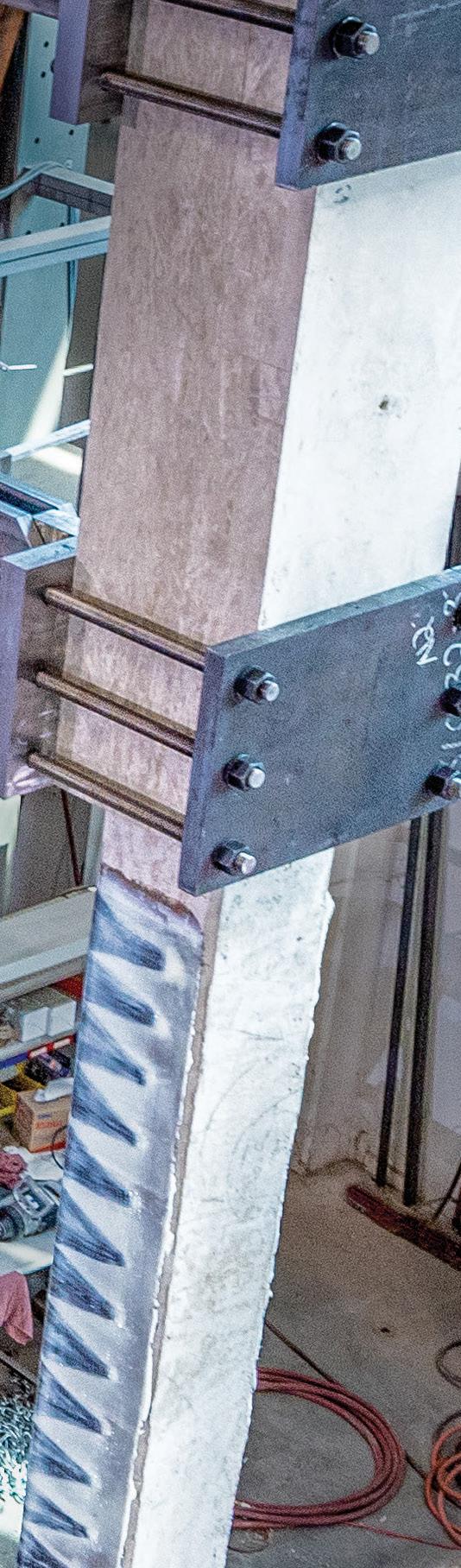
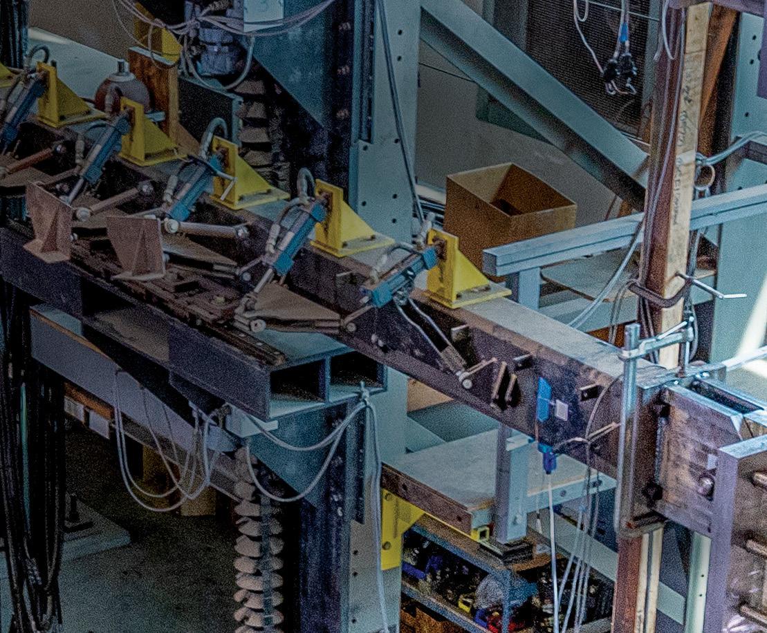
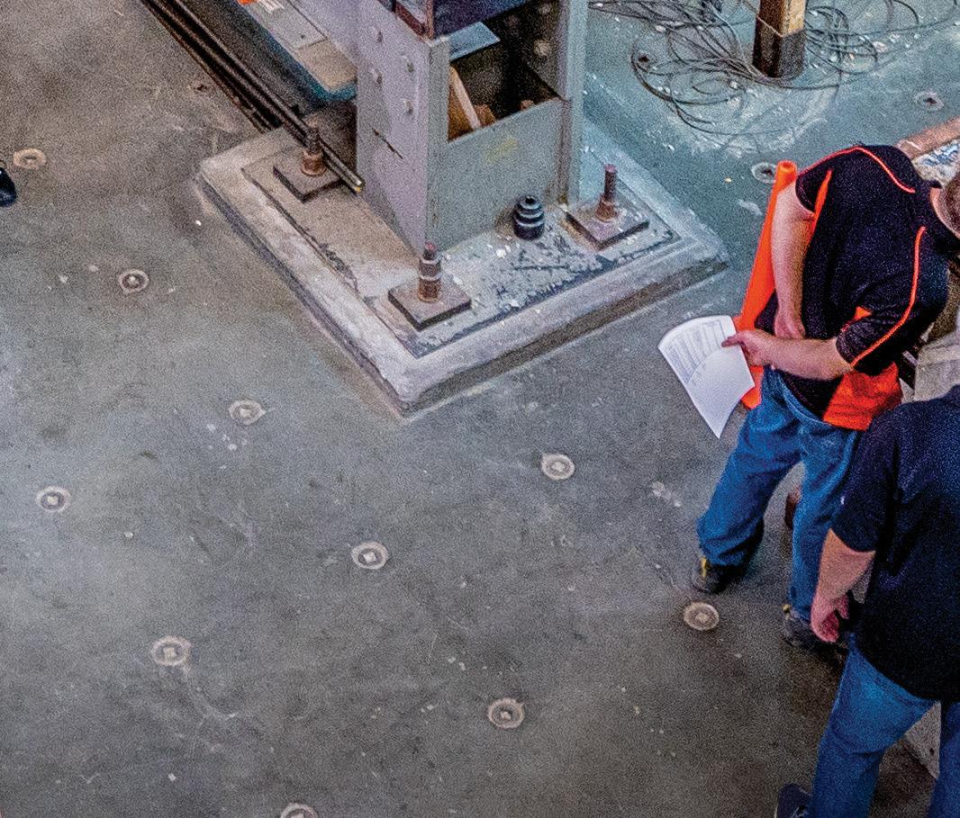
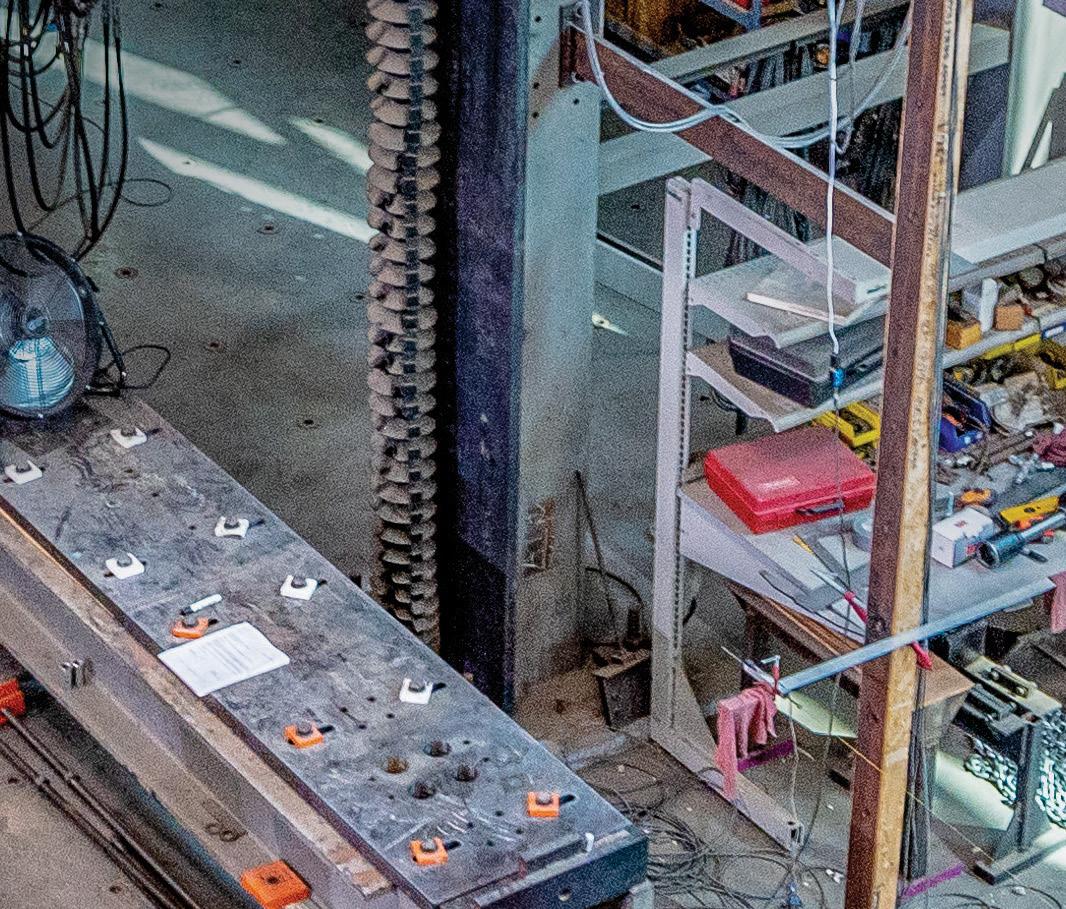
In concrete and masonry, the only true strength is tested strength. That’s why the Simpson Strong-Tie and Structural Technologies alliance is committed to full-scale product testing of Composite Strengthening Systems™ in a variety of applications. Our laboratories and facilities ensure products are rigorously tested and load rated for real-world, as-built conditions. It’s all part of a complete solution with innovative products, engineering services, and technical and field support. So whether you’re planning to strengthen, repair or design with concrete or masonry, you can move ahead with confidence. Set a solid foundation for success. To learn more about our testing capabilities and concrete and masonry solutions, visit go.strongtie.com/alliance or call (800) 999-5099.
Director for Sales, Marketing & Business Development Monica Shripka Tel: 773-974-6561 monica.shripka@STRUCTUREmag.org
Executive Editor Alfred Spada aspada@ncsea.com
Publisher Christine M. Sloat, P.E. csloat@STRUCTUREmag.org
Associate Publisher Nikki Alger nalger@STRUCTUREmag.org
Creative Director Tara Smith graphics@STRUCTUREmag.org
Chair John A. Dal Pino, S.E. FTF Engineering, Inc., San Francisco, CA chair@STRUCTUREmag.org
Jeremy L. Achter, S.E., LEED AP ARW Engineers, Ogden, UT
Erin Conaway, P.E. AISC, Littleton, CO
Linda M. Kaplan, P.E. Pennoni, Pittsburgh, PA
Charles “Chuck” F. King, P.E. Urban Engineers of New York, New York, NY
Nicholas Lang, P.E. Masonry Industry Representative
Jessica Mandrick, P.E., S.E., LEED AP Gilsanz Murray Steficek, LLP, New York, NY
Jason McCool, P.E. Robbins Engineering Consultants, Little Rock, AR Brian W. Miller Davis, CA
Evans Mountzouris, P.E. Retired, Milford, CT
John “Buddy” Showalter, P.E. International Code Council, Washington, DC Eytan Solomon, P.E., LEED AP Silman, New York, NY
Jeannette M. Torrents, P.E., S.E., LEED AP JVA, Inc., Boulder, CO
STRUCTURE ® magazine (ISSN 1536 4283) is published monthly by The National Council of Structural Engineers Associations (a nonprofit Association), 20 N. Wacker Drive, Suite 750, Chicago, IL 60606 312.649.4600. Periodical postage paid at Chicago, Il, and at additional mailing offices. STRUCTURE magazine, Volume 29, Number 12, © 2022 by The National Council of Structural Engineers Associations, all rights reserved. Subscription services, back issues and subscription information tel: 312-649-4600, or write to STRUCTURE magazine Circulation, 20 N. Wacker Drive, Suite 750, Chicago, IL 60606.The publication is distributed to members of The National Council of Structural Engineers Associations through a resolution to its bylaws, and to members of CASE and SEI paid by each organization as nominal price subscription for its members as a benefit of their membership. Yearly Subscription in USA $75; $40 For Students; Canada $90; $60 for Canadian Students; Foreign $135, $90 for foreign students. Editorial Office: Send editorial mail to: STRUCTURE magazine, Attn: Editorial, 20 N. Wacker Drive, Suite 750, Chicago, IL 60606. POSTMASTER: Send Address changes to STRUCTURE magazine, 20 N. Wacker Drive, Suite 750, Chicago, IL 60606.
STRUCTURE is a registered trademark of the National Council of Structural Engineers Associations (NCSEA). Articles may not be reproduced in whole or in part without the written permission of the publisher.


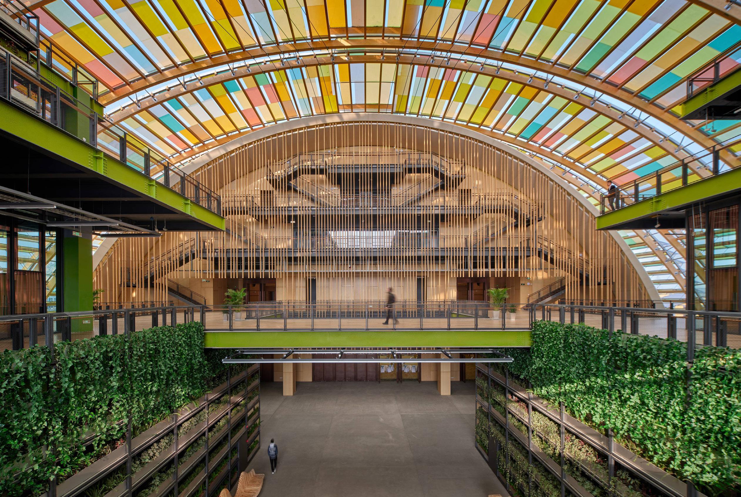
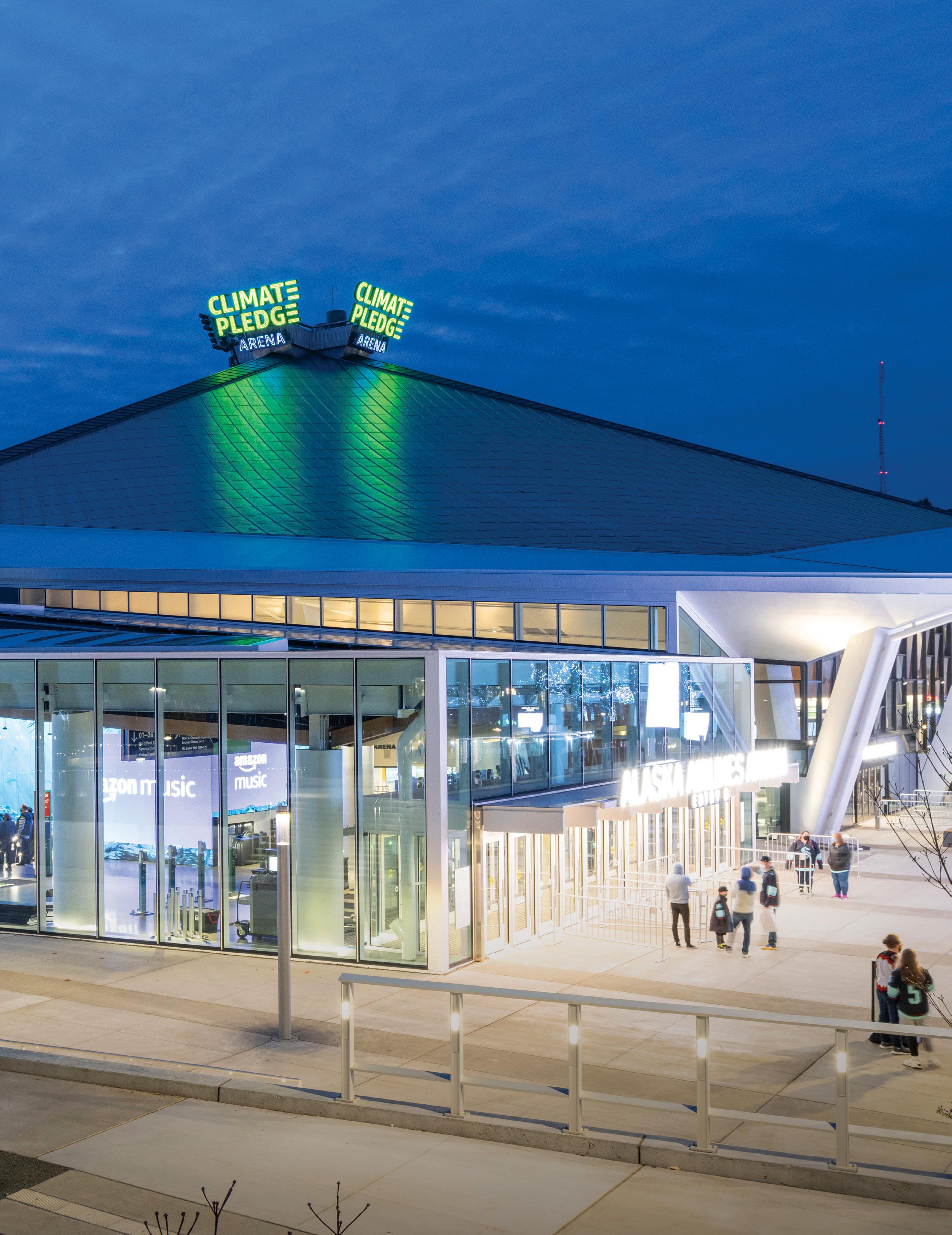
The National Council of Structural Engineers Associations announced the winners of the 2022 Excellence in Structural Engineering Awards in Chicago in November. For 25 years, the awards highlight work from the best and brightest in the structural engineering profession. Read an overview of the award-winning projects. On the Cover: Climate Pledge Arena, Structure of the Year winner and Outstanding Award Winner, Category 7: Forensic/Renovation/Retrofit/Rehabilitation Structures over $20 Million.
By Ben Shock, P.E.
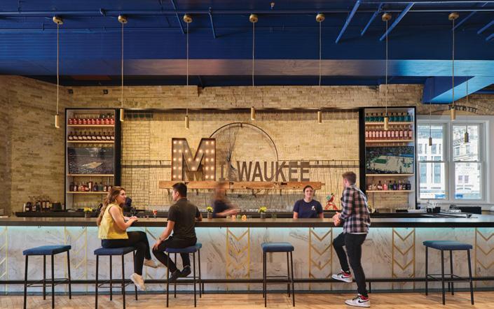
Milwaukee-based Central Standard Craft Dis tillery purchased an 1874 building, with the in herent cracks and imperfections. Unfortunately, these quirks indicated structural distress and the team implemented a top-to-bottom structural retrofit. The structure’s unusual shape was not adjusted or straightened; it was preserved in its current condition with the leaning walls ac counted for in the upgraded lateral system.
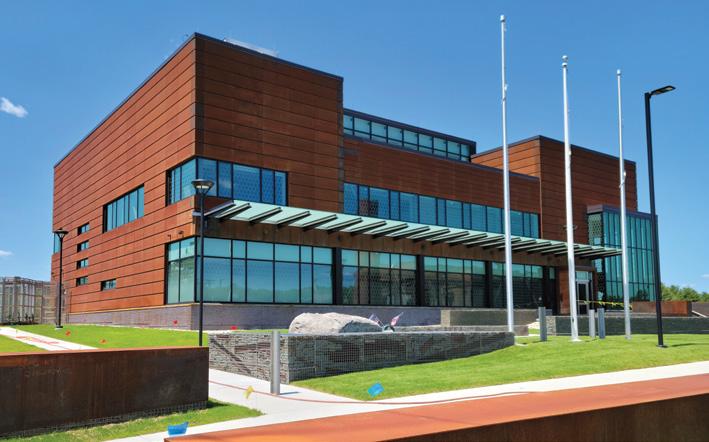
By Jason C. Varney, P.E., Jake E. Hughes, Ph.D., P.E., and Dominic J. Kelly, P.E.
The challenges associated with constructing Mas sachusetts Bay Transportation Authority’s new 24/7 mission-critical Iron Horse Park Operations Control Center, on a site that could liquefy in an earthquake, were identified early, and drove sev eral ground floor and foundation system decisions. Accounting for seismic-induced displacements required considering not only the building super structure but also the foundation system and utilities.
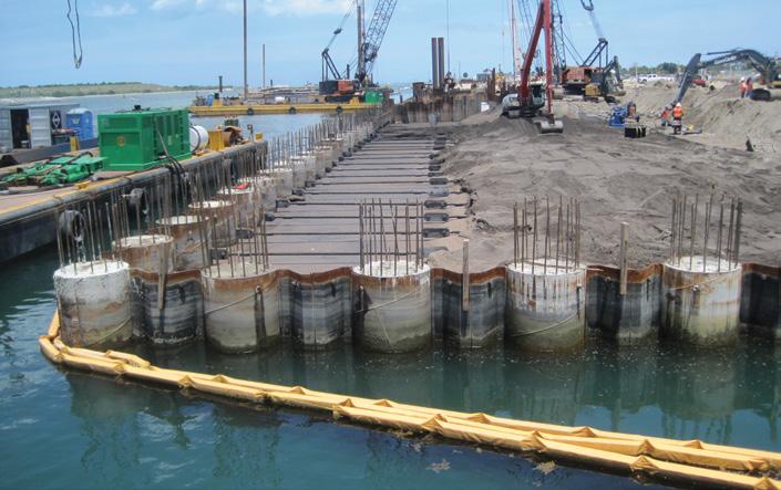
By Jack Moore, P.E.
Creating structurally secure land where there was only ocean was necessary to expand Port Canaveral’s Cruise Terminal 3. A lightweight geotechnical fill made from rotary kiln-pro duced expanded shale, clay, and slate was the solution. The fill’s lightweight aggregate’s low density and high internal friction angle re duced costs. And, the manufacturing process produces a vitrified and durable product that will not degrade.
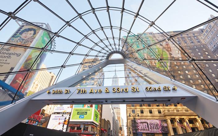
The East End Gateway provides a new direct connection from the street to Penn Station. This 40-foot-tall steel and glass canopy brings natu ral light to the Long Island Railroad concourses below. The canopy frame traces a partial ellipse at its base, which rises to the east towards a canti levered crown. Double-curved glass encloses the western façade, while an inclined planar glass encloses the eastern façade. The curved west façade is supported on cables spanning in two directions between the steel frame.
 By Dylan Richard, P.E., and Stephen Blumenbaum, P.E.
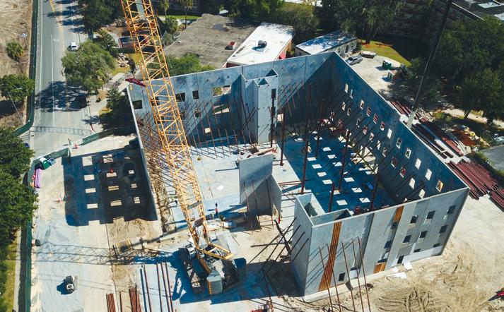
The University of Florida and its Police Depart ment have a new Public Safety Building, a 50,792-square-foot three-story building consist ing of concrete tilt-up wall panels for the exterior and structural steel on the interior. The University approved additional upfront funding for team collaboration during the pre-construction phase. The process created a level playing field for pre-qualified bidders, eliminated waste factors in bids, and aided in awarding contracts.
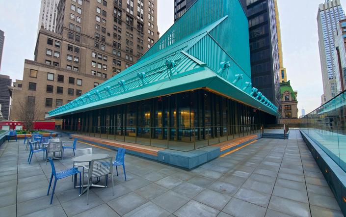
The Mid-Manhattan Library’s renovation included a rooftop addition requiring extending existing columns to create a new platform level. This platform level provided the first floor of a new addition, and a landing point for an irregular column grid required for additional new roof levels above. HSS tube columns, arrayed along the edge of the platform, supported the sloping roof that made up the Wizard’s Hat.


We each face thousands of decisions in our lives. I want to share three of my decisions relative to my practice of structural engineering in the hope that you might find something in common.
During my first structural class as a first-year civil engineering student at the University of Washington, I learned how to design a beam, a column, a slab, and so on. I quickly concluded that structural engineer ing would not be my choice under the civil engineering umbrella. Too many formulas. Too many details. Too many complications. But the next quarter, I took a design course that applied those lessons to reveal how they could be used to create a building. Suddenly a light went on. This was really fun! With those skills, it was possible to design a building that could support gravity, wind, and earthquake loads. All of my joys of building little projects as a youngster could be increased by orders of magnitude...and people would pay me to do it!
I have never looked back. Every day has pro vided challenges, opportunities for creativity, and education. Most importantly, it has led to the development of incredible relationships with other engineers and the many, many people that contribute to the design and construction process. I have learned that our engineering work is not centered on steel, concrete, or wood. It is centered on people. We have a wonderful profession that rewards our members in many ways.
It is possible to practice as a structural engineer and never be involved in a professional society, a technical committee, or “participate” in any way. However, structural engineers today owe a great debt to the engineers that came before them that volunteered and worked to improve the profession.
The potential avenues of support and “giving back” are many. They include your time, talent, energy, and financial resources. All are important and help the cause of professional improvement.
Financial support has the unique benefit of leverage. When combined with other like-minded donors, a financial gift can provide the resources to accomplish tasks that would not be possible by any individual or within the funding of the normal dues structure of a professional society.
There are many opportunities to support a variety of worthy causes. These are important causes such as school support, medical research, and community efforts. And, of course, each person’s decision is usually not which single cause to support but what selections from the charitable menu most closely align with the individual’s values and priorities.
Support of our profession is one of the choices that I have made. The motivation comes from gratitude for previous engineers who built our profession, actions that can improve our practice today, and investing in the people who will be leading our profession in the future.
I have served on the Boards of eleven different non-profit organiza tions, several of them related to the engineering profession. All are worthy of support. What is unique about the SEI Futures Fund?
1) The SEI Futures Fund has global aspirations for improve ment of the profession. Supporting efforts like SEI Global Activities and SEI Codes and Standards work has world wide benefits.
2) SEI Futures Fund grants create benefits for engineers in every state.
3) Structural engineers award SEI Futures Fund grants for structural engineers. Grant recipients are selected by the SEI Futures Fund Board of Directors. Joe Burns, Linda Kaplan, Jim Harris, and Donna Friis are joining me on the Board this year.
4) The largest SEI Futures Fund grants have historically been for “scholar ships.” Not academic scholarships, but support for university students and young professionals to attend Structures Congress and the Electrical Transmission and Substation (ETS) Structures Conference and get involved in SEI. While there is certainly a benefit for the individual recipient, the true beneficiary is the profession. These are the seeds being planted for future leaders.
5) Many other SEI Futures Fund grants match the breadth of the many SEI efforts, from codes and standards to embod ied carbon reduction to improving business practices. Also supported are outreach programs to encourage the best and brightest to enter structural engineering, including those groups that have not done so historically. SEI Futures Fund grants can also support SEI efforts in collaboration with partner organizations.
6) ASCE completely covers SEI Futures Fund fundraising costs. 100% of your donation goes to professional programs benefitting structural engineering.
The SEI Futures Fund is the only engineering philanthropic effort investing in the profession’s future, as described above. The Futures Fund is at the top of my list for financial support of structural engi neering professional efforts.
Every gift, regardless of size, is critically important to improve the profession and prepare for its future. It is a selfless act with great personal benefit for you.
Please join me and many others in support of our profes sion through the SEI Futures Fund. I look forward to seeing your name on the donor list. Please donate at www.asce.org/SEIFuturesFund

■
This two-part series discusses resilience for engineering design practice. Part 1 includes an overview of the ASCE Code of Ethics, resilience concepts for design practice, and how the ASCE Report Card addresses resilience.
The first statement of the new American Society of Civil Engineers (ASCE) Code of Ethics (ASCE 2022) reads, “Engineers govern their professional careers on the following fundamental principles:
• Create safe, resilient, and sustainable infrastructure.
• Treat all persons with respect, dignity, and fairness in a manner that fosters equitable participation without regard to personal identity.
• Consider the current and anticipated needs of society.
• Utilize their knowledge and skills to enhance the quality of life for humanity.”
Also, the Code of Ethics requires that “Engineers adhere to the prin ciples of sustainable development…”. These principles are further developed in ASCE Policy Statement 500, Resilient Infrastructure Initiatives, which states that “...an all-hazard, comprehensive risk assessment that considers event likelihood and consequence, encour ages mitigation strategies, monitors outcomes, and addresses recovery and return to service should be routinely included in the planning/ design process for infrastructure at all government levels.” Although these notions are permeating calls to action by our professional society, concepts of resilience and sustainability are still new to structural engi neers, including how to incorporate these concepts into their projects.
The Code of Ethics has a footnote that states: “This Code does not establish a standard of care, nor should it be interpreted as such.” While this caveat provides an exemption for litigation purposes, the principles established in the Code of Ethics do govern engineering practice and licensure requirements.
The Code of Ethics addresses the responsibilities of five stakehold ers: Society, Natural and Built Environment, Profession, Clients and Employers, and Peers. In the case of a conflict between ethical responsibilities, the stakeholders are listed in the order of priority. The following responsibilities for each stakeholder apply to resilience in engineering practice:

• First and foremost, protect the health, safety, and welfare of the public.
• Enhance the quality of life for humanity.
• Consider and balance societal, environmental, and eco nomic impacts, along with opportunities for improvement, in their work.
• Mitigate or minimize adverse societal, environmental, and economic effects.
• Educate the public on the role of civil engineering in society.
• Encourage and enable the education and development of other engineers and prospective members of the profession.
• Communicate in a timely manner to clients and employers any risks and limitations related to their work.
• Present clearly and promptly the consequences to clients and employers if their engineering judgment is overruled where health, safety, and welfare of the public may be endangered.
• Encourage and enable the education and development of other engineers and prospective members of the profession. Note that the current language for Natural and Built Environment uses sustainability concepts that can also be applied or extended to resilience. Sustainability refers to maintaining and improving the quality of life without degrading the quantity, quality, or availability of natural,
economic, and social resources; sustainability focuses on infrastructure materials and methods for construction, operation, and maintenance. Resilience refers to maintaining and improving societal functions by designing and preparing for rapid infrastructure recovery following damaging events; resilience focuses on discrete hazard events and chronic conditions (e.g., sea level rise) that reduce or impair infra structure functionality. Project goals for both concepts require the development of integrated or compatible design criteria.
Community resilience addresses societal needs, among other factors, such as safety and performance. For the built environment, community resilience relies upon the ability of infrastructure to enable functions and services, such as housing, commerce, water, power, communica tion, and transportation services, under daily operational conditions and severe stressors due to hazard events. Community resilience goals inform performance objectives for the built environment before, during, and after hazard events.
Engineers have a key role in educating stakeholders about the benefits of resilience in designing new buildings and infrastructure systems and monitoring, maintaining, and upgrading existing infrastructure.
Engineers need to be involved earlier in project planning, where soci etal needs are established regarding minimum or acceptable outcomes following hazard impacts. Early involvement allows engineers to hear the performance requirements identified by planners and designers and help them determine if the performance of existing building stock is adequate or if new requirements are needed. The structural engineers’ involvement can give a unique perspective and identify opportunities others may not see.
Suppose a designer is requested to consider a building as part of a community resilience plan (regardless of occupancy/function). In that case, the designer needs to discuss the expected performance of the facility with the client. Based on the client’s needs, this may be beyond what is prescribed in current codes and standards and may require the use of Performance-Based Design (PBD) to address recovery of function and other considerations.
Typically, discussions about projects are limited to potential clients. However, if the architect is excluded during these discussions, the potential ramifications of exclusive focus on structural optimization may reduce the long-term business benefit. Structural engineers must talk to architects and owners (the architect’s client) in an educational capacity at the onset of project inception. These discus sions should include a planning group that includes key community stakeholders and considers the project’s contribution to maintain ing community functions and lessening recovery time following a disruptive hazard event.
Specific occupancies should always target higher performance levels (e.g., Risk Category III and IV), but, in some cases, large and multiple-purpose buildings may be identified as essential to community functions. For example, imagine a situation where a municipality identifies which critical facilities are needed for its functional recovery and determines they have gaps (e.g., they need
a large shelter). Then, a development plan to build a multi-purpose facility can address the social needs that serve the community now and into the future.
According to the literature and policy statements, the common aspects of resilience are “the ability to prepare for and adapt to changing conditions and withstand and recover rapidly from disruptions” (Koliou et al., 2018). The performance of the built environment, and its support of social, economic, and public institutions, is essential for a community’s immediate response and long-term recovery after a disruptive natural hazard event.
Civil infrastructure, on which any community’s economic and social well-being depends, is susceptible to damage and/or disruptions to functionality due to natural hazards. While new buildings and infra structure tend to perform as expected for design-level events, existing buildings and infrastructure are typically more susceptible to damage during the same events. Furthermore, engineers are challenged to design for nonstationary hazard conditions due to climate change; for example, when environmental conditions (e.g., sea level, rainfall intensity, wind speed, etc.) associated with a design-level event are expected to increase over a project’s design life.
Upgrading and constructing buildings and infrastructure to the latest codes and standards improve their performance and community resilience for hazard events. However, new construction built to the latest codes and standards is still subject to damage that may impair their use or intended functions, as codes and standards primarily focus on life safety. Damage to existing infrastructure often produces dis proportionate economic and social losses, especially for lower-income households and other vulnerable segments of society. How we choose to construct our infrastructure opens the door to future disasters, as design choices have an impact on society. Regardless of wealth or political capital, communities expect and deserve infrastructure investments that meet community needs.
The needs of community members and social institutions – including government, industry, business, education, and health – help define functional requirements for community buildings and infrastructure (Figure 1). For instance, can residents remain in their homes after a significant event? Can governments communicate with
residents
…new construction built to the latest codes and standards is still subject to damage that may impair their use or intended functions, as codes and standards primarily focus on life safety.
to inform them and support recovery efforts? Can businesses and factories resume operations within a reasonable period? These social needs determine the performance expected from buildings and infra structure (NIST, 2016).
Resilient design concepts for individual building or infrastructure projects may include 1) location considerations to mitigate hazard exposure, 2) design or mitigation features to withstand and minimize load effects (e.g., limiting structural drift impacts on nonstructural systems), 3) limiting member failure to a specified location and manner (e.g., local ductile failure without structural instability), 4) design adaptation for future anticipated conditions and events, and 5) design or mitigation features to improve the time to recovery of function after a hazard event.
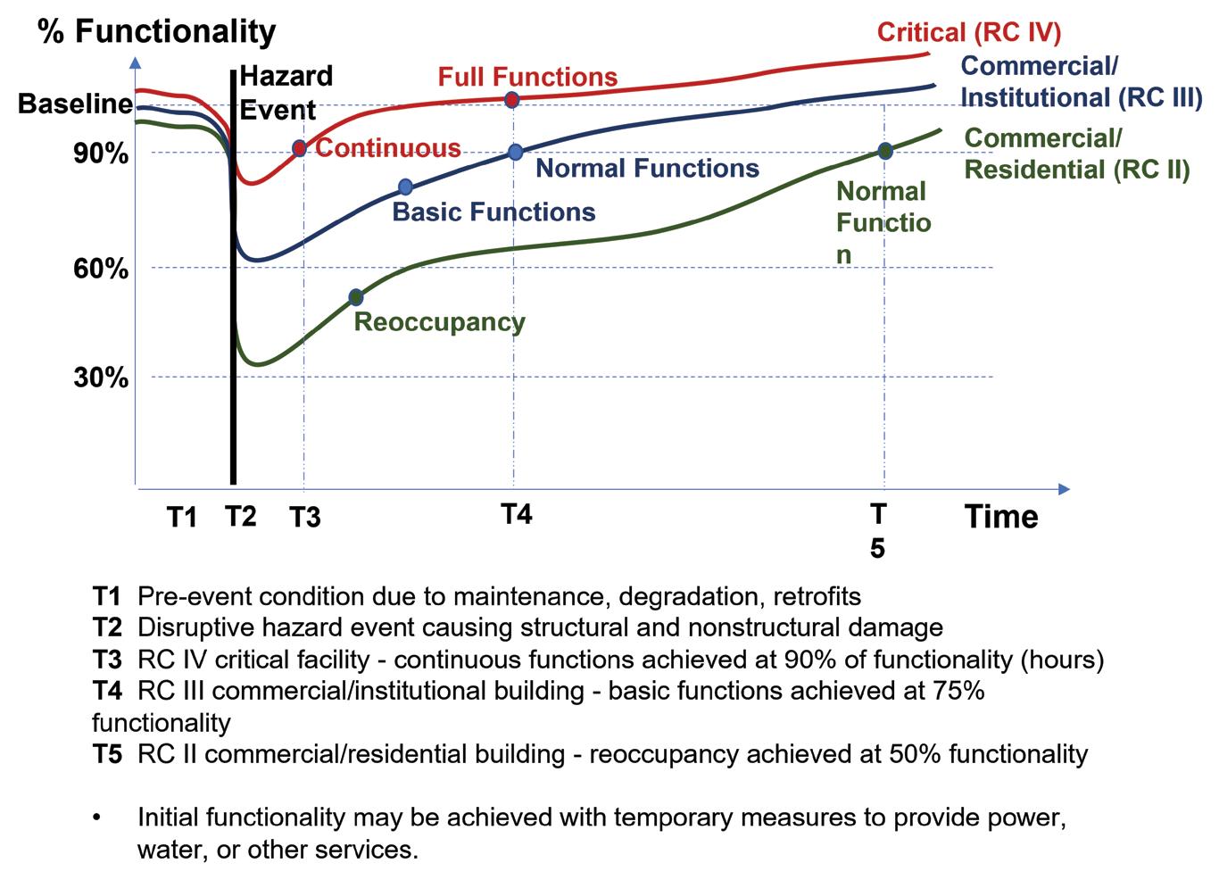
Recovery of function, or functional recovery, after a damaging event, depends on the extent of damage and repairs and the ability to obtain operational supplies and resume organizational operations. A building may have reduced functionality because of structural or nonstructural damage or service loss from external infrastructure systems. A building’s functional recovery may involve temporary solutions while repairs to internal or external systems are underway. Recommended Options for Improving the Built Environment for PostEarthquake Reoccupancy and Functional Recovery Time (FEMA/NIST 2021) provides additional guidance that focuses on the recovery of individual buildings and infrastructure systems.
Functionality is measured relative to a baseline level, often defined by pre-event conditions. Functional recovery measures the time to achieve distinct performance states, such as re-occupancy (safe re-entry for shelter or protecting contents), basic functions/operability (system provides its regular pre-event services, with temporary solutions as needed), and full function (all functions restored to pre-event levels and all repairs completed). Figure 2 depicts how the percentage of facility functionality versus recovery time can help specify performance states for buildings and infrastructure based on their Risk Category (RC) (McAllister 2022).
Resilience needs are articulated by the ASCE (2021a) Report Card as follows: “We must utilize new approaches, materials,
and technologies to ensure our infrastructure can withstand or quickly recover from natural or man-made hazards.”
Advancements in resilience across all infrastructure sectors can be made by:
1) Incentivizing and enforcing the use of codes and standards to mitigate the risks of major climate events such as hurricanes, fires, sea level rise, manmade events, and more.
2) Understanding that our infrastructure is a system of systems encouraging a dynamic, big-picture perspective that weighs tradeoffs across infrastructure sectors while keeping resilience as the chief goal.
3) Prioritizing projects that improve the safety and security of systems and communities to ensure continued reliability and enhanced resilience.
4) Improving land use planning across all decision-making levels to strike a balance between the built and natural environments while meeting community needs, now and into the future.
5) Incorporating natural or “green” infrastructure to enhance the resilience of various infrastructure sectors. Leveraging natural infrastructure in engineering design can mitigate the effects of natural and manufactured hazards while improving environmental assets and social capital. In addition, such designs can extend the design life of existing infrastructure by lessening environmental loadings or serving as a “first line of defense” in innovative designs that consider non-static load conditions under future climate scenarios.
Engineers can support community resilience goals by incorporating them into building and infrastructure design practice. For example, community goals can be addressed by a project with specific resilience requirements to guide its performance, damage states, and functional recovery for design hazard events.
The needs of community members and social institutions – including government, industry, business, education, and health – help define functional requirements for community buildings and infrastructure. Functionality and functional recovery measures, such as re-occupancy, basic functions/operability, and full functions, need to be assessed relative to the role of the building or infrastructure system in the community.
Engineers have a key role in educating stakeholders about the ben efits of resilience in new and existing buildings and infrastructure systems. Being involved in project planning when societal needs are established allows for consideration of options such as increasing the Risk Category or using PBD for performance objectives beyond those achieved with codes and standards. Such decisions and design choices set the stage for future hazards and societal impacts. All communities expect and deserve infrastructure invest ments that meet community needs.
■

References are included in the PDF version of the online article at STRUCTUREmag.org
The mission of the SEI Resilience Committee is to advance structural engineering professional practice by developing programs and resources to support engineering professionals working toward enhancing resilience.

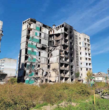
On October 10, 2022, Russia escalated its war against Ukraine with the largest wave of airstrikes against civilian infrastructure since the invasion began last February. Targets included energy utili ties, apartment blocks, and houses. Dr. Kit Miyamoto led a team of global engineering experts working with the U.N. in Kyiv, Ukraine’s capital, to assess infrastructure damages caused by the war.
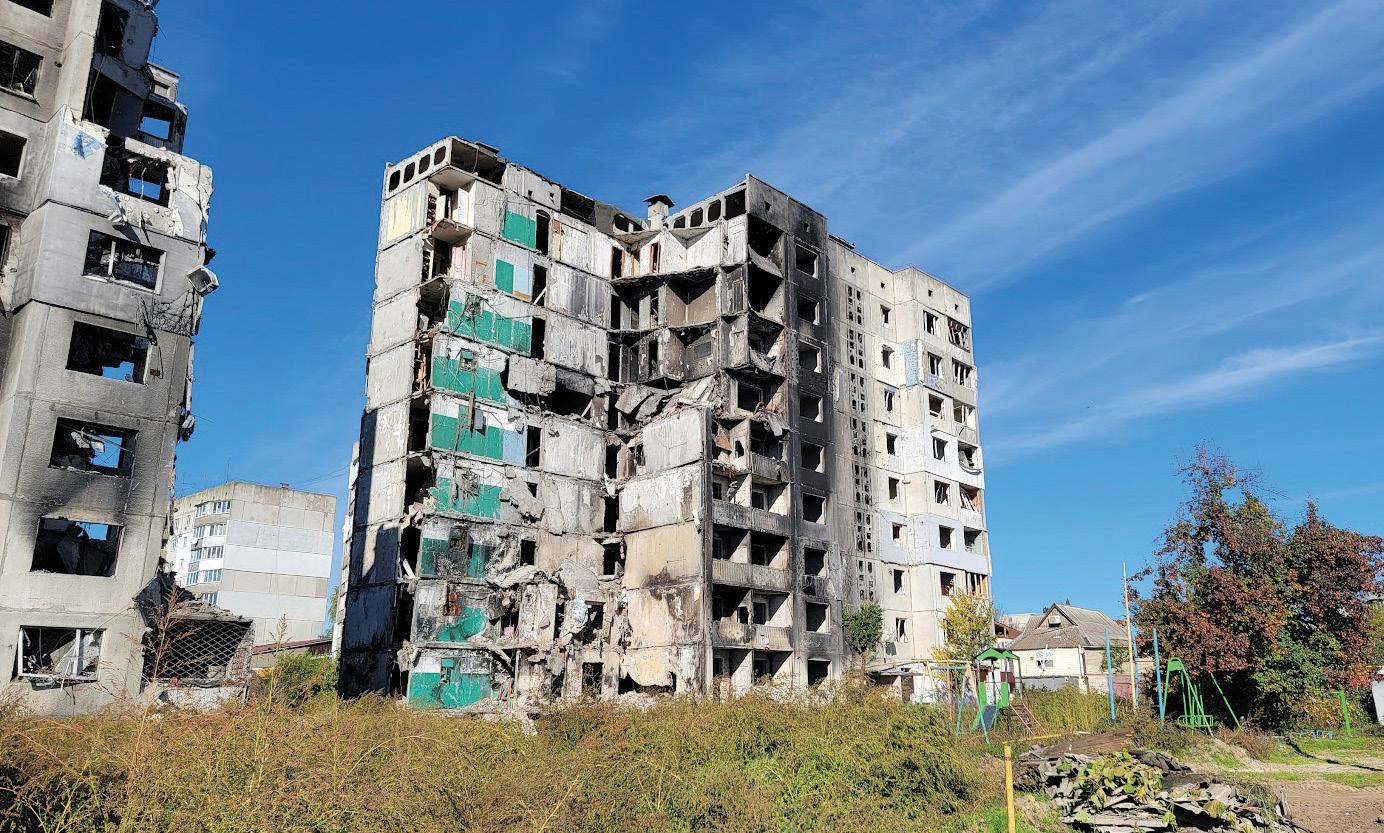
The team witnessed that Ukrainians responded to these attacks with calm and resilience. Dr. Miyamoto wrote that day that “All destroyed Russian tanks were removed and put into a museum display, and bombed highways and bridges were repaired. Restaurants, busi nesses, and schools were open despite the daily early morning air raid siren. Russian missiles still penetrate through a couple of high-rise apartments. But people were calm, ready to restart their lives and reconstruct the country.”
Dr. Miyamoto kept a journal recounting his experience during the attack.
8:22 AM
I just heard a large air blast as I was making my morning coffee. It was a sonic-like blast followed by a line of collapsing buildings, the sound of which I have heard often in the past during earthquakes. We have all been extremely nervous since the Crimea Bridge blast a couple of days ago. I am in the newly built Radisson hotel in old town Kyiv, intentionally avoiding public buildings or large apartments that Russian forces can target.
I am not sure where the blasts are coming from; it could be a gas explosion somewhere. I hear fire truck sirens off in the distance and look out the window to see if I can spot anything. But, instead, my eyes are met with a woman next door, a mobile phone in her hand, and a little girl nervously peering through a curtain.
9:15 AM
Our Ukraine country manager, Pavlo, has messaged me that a Russian missile hit about 1 km from our hotel. He sends me videos of burn ing cars. He got stuck in town last night and slept at his friend’s apartment nearby.
I heard a second blast. My small room is shaking. This is not a drill; this is a real air raid. Sabine is awake, and we quickly run to the basement shelter.
10:38 AM
We are now stuck in the basement shelter with a group of hotel guests. I’d estimate nearly one hundred of them. They all look like humanitarian assistance types. Some are wearing their NGO logo shirts, and some wear press credentials. Many are working on laptops. The hotel provided some sleeping pads. Unfortunately, Sabine and I did not get one, just an old desk and two chairs. No complaints from me. We are fortunate to have this space.
12:32 AM
Pavlo calls and tells me he is hiding in a basement café with food next door to us. That sounds better, and we go to his location and order a proper breakfast. The people in the Cafe are calm, and the next table over orders a bottle of local orange wine while waiting for the air raid sirens to be done.
The news is saying that Russia retaliated for what it claimed was a “Ukrainian attack on a critical bridge.” Russia’s attacks shattered buildings and killed at least eleven people.
4:31 PM
Pavlo, Sabine, and I are back in the office near the city center. We begin writing flow charts of the reconstruction schedule and deploy ment. This week, we need to develop reconstruction programs for the damaged houses in all affected areas.
We will be working with U.N. agencies and assembling a local team to start repairing damaged housing units and high-rise buildings. People need proper shelter now. Many live in shell-damaged and burned apartments since they have no other means. Tank shell and missile damages are technically localized, therefore, simpler to repair than damages caused by earthquakes.
■
“We can really assist people here back to normality. As an Irpin city official said, ‘Destroyed but Not Conquered.’ Incredible people.”
Dr. Kit Miyamoto
Dr. Kit Miyamoto is a world-leading expert in disaster resiliency, response, and reconstruction. He provides expert engineering and policy consultation to the World Bank, USAID, U.N. agencies, governments, and the private sector. He is a California Seismic Safety Commissioner and Global CEO of Miyamoto International.
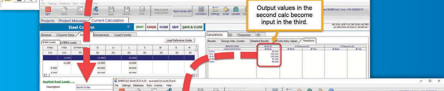
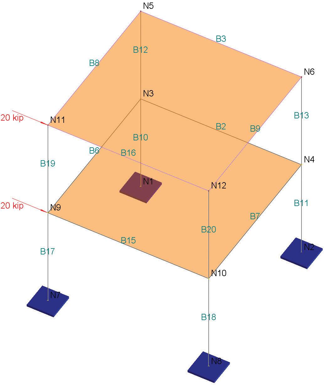
Numbers in computers can only be represented by a fixed number of digits. The predominant number type in Finite Element Method (FEM) software packages is Double-Precision, which is 8 bytes in size. This gives about 15 digits of accuracy. However, during the solution of FEM equations, numerical difficulties or errors may be encountered in certain modeling scenarios due to truncation and round-off errors. The introduction of the Quad-Precision number type, 16 bytes in size providing about a 34-digit accuracy, can reduce FEM solution errors. The author presents a few examples to illustrate the differences in using Double Precision and Quad Precision numbers. A few types of errors are associated with finite element/structural analysis programs.
1) Input/output errors: user input mistakes while entering input data or misinterpreting program results.
2) Modeling errors: assumptions made in the formulation of mathematical models (e.g., using elastic material properties for concrete).
3) Discretization errors: using discretized finite element models for continuous mathematical models (e.g., using straight ele ments to model a curved edge).
4) Solution errors: numerical errors during the process of numerical solutions of finite element equations. Although all the above errors are important, this article focuses on solution errors.
Finite element solutions boil down to solving a system of linear equations: [K]{u} = {R} (Eqn 1)
where [K] is the global stiffness matrix, {u} is the displacement vector, and {R} is the load vector.
During the solution of the above system of linear equations, trun cation errors, round-off errors, and accumulation errors can be experienced. This article illustrates these errors through examples.
Numbers, like any other information in computers, are represented by bytes. A byte consists of eight bits. One bit can represent 2 states (on and off), two bits can represent 22 states, and so on. Therefore, a byte can represent 28 = 256 states. There are two main floating-point (non-integral) number types in computers: 4-byte (or 32-bit) singleprecision type and 8-byte (or 64-bit) double-precision type.
As we all know, infinite numbers exist between any two different numbers. So how can we represent numbers accurately with a limited number of bits or bytes in a computer? The answer is we cannot. We
can only represent numbers in a computer by approximation. For the 32-bit single-precision number type, we generally use 1 bit to represent signs (positive or negative), 8 bits to represent exponents, and 23 bits to represent actual digits. Since 223 = 8388608, it can be said that a single-precision number has an accuracy of about 7 significant digits. For the 64-bit double-precision number type, we generally use 1 bit to represent signs, 11 bits to represent exponents, and 52 bits to represent actual digits. Since 252 = 4.5 E15, a double-precision number could be viewed as having an accuracy of about 16 significant digits.
The concept of significant digits can have unexpected results in soft ware computations. For example, if we have three double-precision numbers x = 1.234e18; y = 0.1; z = x + y; both x and z will still equal to 1.234e18. A more serious issue is that the number y / (z–x) yields infinity instead of 1. In today’s finite element programs, double preci sion is the predominant number type used in their implementations and is sufficient in most cases. However, double precision may not be accurate enough in some uncommon cases.
Suppose we have the following system of equations in matrix form [K]{u} = {R}
(Eqn 2) 22500000 −9375000 −9375000 9375000 115.3144 6.3810 = [ ( ( ) ) ] Q 2 Q 3
Solving the equations by the Gauss elimination method using 15 significant digits yields the following “accurate” solution: 9.27203047619049e − 06 9.95267047619048e − 06 ( ) = ( ) Q 2 Q 3
Now pretend that a computer can only represent each number accurately to 3 significant digits. Then the original system of equa tions Equation 2 becomes
(Eqn 3) 22500000 –9380000 –9380000 9380000 115 6.38 [ ( ) ] = ( ) Q 2 Q 3
Here, we chopped off the stiffness matrix and load vector terms from Equation 2 to 3 significant digits. Therefore, we have a truncation error introduced in Equation 3 even if we solve the equations accu rately with 15 significant digits. If we continue to solve the equations with 3 significant digits in each arithmetic step, additional round-off errors are introduced, and the following solution results:
9.24e − 06 9.95e − 06 ( ) = ( ) Q 2 Q 3
The accumulated truncation and round-off errors, r2 and r3, for displacements Q2 and Q3 are:
= ( ) r 2 r 3 ( ) (9.27203047619049 − 9.24)e − 06 (9.95267047619048 − 9.95)e − 06 =
( ) 0.03203047619049e − 06 0.00267047619048e − 06
In forming the global stiffness [K] in Equation 3, each stiffness term Kij is calculated by adding the relevant stiffness terms of all elements connected to the associated degree of freedom. For simplicity’s sake, assume Kij comes from two elements with the relevant element stiff ness terms k1 and k2; thus, Kij = k1 + k2. If k1 is much smaller than k2 (or vice versa), significant information is irrevocably lost due to truncation error. As a result, the solution for displacements may be inaccurate, incorrect, or impossible.
The following simple structure consists of two 10-foot one-dimensional elements (Figure 1) and is subjected to an axial load of 1 kip at the tip. The material’s modulus of elasticity, E, equals 29000 kips per square inch (ksi). The first element (B1) has a cross-sectional area of 0.0001 inches2. We vary the cross-sectional area of the second element (B2) using 0.0001, 0.01, 1, 100, 10000, 1e+06, 1e+10, 1e+12, and 1e+14 inches2. The results in Table 1 are from a Real3D software program using double-precision arithmetic.
The results deteriorate as the stiffness mismatch between the two elements becomes larger. The result becomes inaccurate when k2/k1 = 1.00e10 / 0.0001 = 1.0e14, unreliable when k2/k1 = 1.00e12
/ 0.0001 = 1.0e16, and unattainable when k2/k1 = 1.00e14/0.0001 = 1.0e18. This behavior is expected due to the double-precision number having an accuracy of about 16 significant digits.
Numerical difficulties may also arise due to the accumulation of round-off errors, primarily when a model consists of a large number of elements. The following cantilever beam example is modeled with multiple segments of equal lengths, thus without any element stiff ness mismatches.
A 100-inch-long horizontal cantilever beam is subjected to a vertical point load of -10,000 pounds (lbs.) at the tip.
Material properties: E = 2.9e7 pounds per square inch (psi), Poisson’s ratio, ν = 0.3
Section properties: a moment of inertia I = 200 inches^4
Model the beam with 1; 1,000; 10,000; 20,000; and 50,000 mem bers or segments.
Also, beam shear deformations are not considered. The displacement and rotation at the tip of the beam may be cal culated by hand as follows:
Δ = PL3 3EI = −0.5747 inches (shear deformation ignored)
θ = PL2 2EI = −0.00862 radians
The results in Table 2 are from the Real3D software program using a double-precision solver and a quad-precision solver.
is example is probably the simplest structural model that can be solved by either hand or an analysis program. However, it could be a very challenging numerical problem, as shown. e standard double-precision solver tends to deteriorate in solution accuracy as the number of elements increases. In the example, the solver becomes unstable after 10,000 elements. For the model with 50,000 elements, some diagonal terms in the global stiffness matrix become negative during the factorization process due to round-off errors. As a result, the solver has to terminate, and the solution is no longer obtainable. No results are actually better than wrong results. You are encouraged to solve this model with your familiar structural analysis software!
Double-precision skyline arithmetic

Rz @Node 2 (Kip) 49.044 49.044 49.044
Rz @Node 24 (Kip) 225.242 223.343 229.849
Rz @Node 53 (Kip) 351.108 351.108 351.108
Total Support Reaction (Kip)625.394 623.495 630.000
e quad precision solver is much more accurate and stable. e quad-precision number type uses 16 bytes or 128 bits with 1 bit to represent signs, 15 bits to represent exponents, and 112 bits to represent actual digits. It has an accuracy of about 34 significant digits. (Can you figure out why? It’s because 2^112 = 5.2E33). erefore, it is more tolerant to round-off error accumulation. Consistent and correct from the quad precision solver’s results demonstrate its superior accuracy for up to 50,000 or more elements for this example.
e following 700-foot continuous bridge (Figure 2, page 13 ) is discretized into multiple segments of different lengths: 0.3, 9.7, 20@10, 0.3, 9.7, 27@10, 0.3, 9.7, 20@10 feet. Each segmented beam is subjected to a uniform load of -0.9 kip/ft in the global Z-direction.
Material: E = 30457.9 ksi, ν = 0.25
Sections: Izz = 2.40251e + 06 in4 , Iyy = 619965 in4, J = 2.40251e+06 in4, A = 255.441 in2, Ay = Az = 0.0 in2
Support conditions:
@Node 2: restrained in Dx, Dy, Dz, and Dox degrees of freedom @Node 24: restrained in Dy, Dz, and Dox rotational degrees of freedom. ere is a large support settlement of 14.5107 inches in the Z direction.
@Node 53: restrained in Dy, Dz, and Dox degrees of freedom e results in Table 3 are from the Real3D software program using the double-precision skyline matrix solver, double-precision sparse matrix solver, and quad-precision skyline matrix solver (see Note 1). e total support reaction in the Z direction should be 700 ft * 0.9 kip/ft = 630 kips. However, as shown, both the double-precision skyline solver and sparse solver give an inaccurate support reaction at Node 24 that is reflected in the total support reaction. e reasons for this inaccuracy are due to the following:
1) ere is a significant stiffness variation between adjacent beams at the support.

2) e Real3D software program uses a penalty approach (see Note 2) to enforce support restraints when constructing global stiffness matrices.
3) e support settlement (load value) is large. ese reasons result in significant truncation and round-off errors with double-precision arithmetic. On the other hand, the quad precision arithmetic yields an accurate support reaction at Node 24. *Note 1: e skyline and sparse matrix refer to how the global stiffness matrix is stored. e sparse matrix solver generally uses much less memory and runs faster than the skyline matrix solver. Note 2: e penalty approach uses springs with large stiffness values to model supports. is approach is popular among structural analysis software implementations due to its simplicity and intuitiveness.
In modeling rigid diaphragms such as a concrete floor in a frame, master-slave (where slave nodes are constrained to follow a master node) degrees of freedom DX, DZ, and DOY (rotation about the global Y axis) could be used, assuming Y is the vertical axis. is is mathematically imposing constraint equations in the global stiffness matrix. However, this approach may not be ideal since DX and DZ are not equal for all the nodes on the diaphragm plane when subjected to unsymmetrical loading. A more reasonable way to model rigid diaphragms (Figure 3) is to add fictitious members with very large in-plane stiffnesses relative to the model’s actual members. e fictitious members must be interconnected with all the nodes on the diaphragm plane. ese fictitious members can then be assigned large material properties and in-plane sectional properties based on those of actual members and a large stiffness multiplier (say 1.0e4). is ensures the rigid in-plane diaphragm action. Some structural software programs in the market implement this feature automatically.
A potential problem with the second approach is using a large stiffness multiplier in the double-precision solver. It artificially increases the mismatch of member stiffness terms, thus increasing the likelihood of numerical difficulties during the solution. With quad precision, this problem can be easily avoided.

As the previous examples show, structural analysis software programs may not always yield accurate results. ere are some inherent errors associated with constructing and solving systems of equations. In certain situations, these errors may become intolerable. Of course, structural analysis software, like any other software program, may contain defects (i.e., software bugs). A good structural engineer should not blindly trust software results.
If possible, a suitable software program should warn users when numerical difficulties or errors are encountered during a solution. A useful measure is the number of significant digits lost during the analysis solution. It can be computed based on the diagonal decay ratio (ri) as defined below.
where Kii is the original diagonal coefficient of the global stiffness matrix, and Pii is the reduced value of Kii just before it is used for back-substitution. e number of significant digits lost is about log10(ri). For example, if ri is 108, then 8 digits are lost. e results given by double-precision solvers may be unreliable if 12 or more significant digits are lost during the solution process. e following are a few tips to minimize solution errors when using structural analysis software:

a) Avoid large stiffness differences between adjacent elements. For example, for one-dimensional frame members, the member lengths should not vary too much; for two- or three- dimension finite elements such as shells or brick elements, the element sizes and shapes should be close or nearly the same.
b) Use master-slave degrees of freedom if possible (e.g., use displacement constraints for rigid beams in two-dimensional frames).
c) Use higher precision (e.g., quadprecision) number arithmetic if needed. If your software vendor does not currently support it, ask for it. It should be noted that quadprecision numbers take twice as much memory as double-precision numbers. It is also significantly
slower due to the lack of direct hardware support and extra calculations.
d) Never use any finite element software programs that use singleprecision arithmetic in their solver. is may be a problem in some older structural software programs when computer memory was a premium. Single-precision number types should not be used in finite element implementations.
e) Pay attention to software errors or warning messages such as significant digits lost during factorization of global stiffness matrices.
f) Check if the summation of support reactions is equal to the total load. Since finite element implementations are displacement-based, if displacements are unreliable due to unstable solutions, all other results, such as support reactions, are unreliable.■


References are included in the PDF version of the online article at STRUCTUREmag.org
Junlin Xu is the President of Computations & Graphics, Inc. and the author of the Real3D structural analysis program (junlin_xu@cg-inc.com).
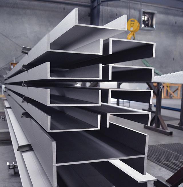
With the increasing focus on resilience, interest in stainless steel has likewise grown. As part of that growth, a new design specification for structural stainless steel and a new companion code of standard practice were approved by AISC in 2021. These two docu ments, Specification for Structural Stainless Steel Buildings (ANSI/AISC 370-21) and Code of Standard Practice for Structural Stainless Steel Buildings (AISC 313-21), are the first standards in the U.S. to address hot-rolled, extruded, and welded stainless steel sections. The new specifi cation (AISC 370) builds on the first edition of AISC Design Guide 27: Structural Stainless Steel, published in 2013, updating it to incorporate the results of the latest worldwide research on the behavior of stainless steel structural elements. In addition, a new edition of AISC Design Guide 27 was published in April 2022, with extensive tables and supporting material to supplement the AISC 370 specification.
Stainless steel is a family of corrosion-resistant and heat-resistant steels containing a minimum of 10.5% chromium and a maximum of 1.20% carbon. There are five basic groups of stainless steel: austenitic, ferritic, duplex, martensitic, and precipitation-hardening. There are hundreds of different alloys, but only a few are used in the construc tion industry. AISC 370 applies to specific austenitic and duplex alloys, with some provisions for the use of precipitation-hardening alloys for tension members, fittings, and fasteners.
Stainless steel is used for its corrosion resistance, which comes from a very thin chromium-rich oxide layer on the surface. This protective layer is referred to as a passive layer or passive film because it forms naturally and spontaneously under normal environmental conditions within about 24 hours and does not react further with the atmosphere once formed. Many factors go into selecting appropriate alloy(s) for a specific application, some of which are addressed in Chapter A of AISC 370 and in Design Guide 27. This article focuses only on the provisions in AISC 370 for the design of members in Chapters B through H.
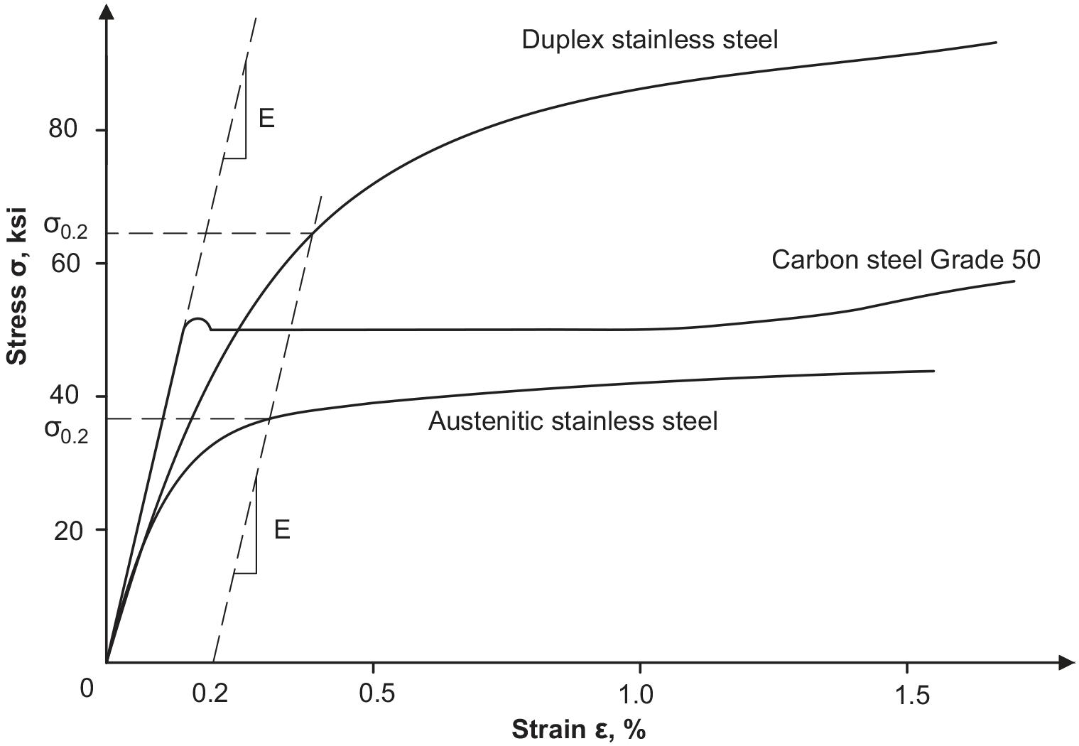
The primary difference in the structural behavior of stainless steel when compared to carbon steel is the shape of the stress-strain curve. As shown in Figure 1, typical carbon steels have a linear stress-strain relationship up to a definite yield point, after which stress no longer increases with strain. For stainless steel, the limit of proportionality, the point at which the stress-strain curve becomes non-linear, is very low, and the stress-strain curve has a rounded appearance, which results in a gradual reduction of stiffness as the stress increases. This stress-strain relationship generally affects limit states associated with local and global buckling, which are dependent on stiffness.
AISC 370 follows the same format as the Specification for Structural Steel Buildings (ANSI/ AISC 360-16). The table of contents is almost identical, limit states are generally the same, and design methodologies are generally the same. Also, structural stainless steel can be designed using the same analysis methods as for carbon steel. Engineers accustomed to using AISC 360 to design carbon steel should find AISC 370 familiar. In most cases, the equations in AISC 370 are quite similar in format, although they may look slightly different, with different con stants or coefficients.
One of the significant differences between carbon steel and stainless steel is not in the design of members but in the availability of sections. Wide flange, channels, angles, and round and rectangular hollow structural sections are all avail able in several stainless steel alloys. However, hot-rolled stainless steel sections are available only up to about eight inches. Beyond that, sections are built-up from plates with either fillet welds or laser-hybrid welds. This means one can specify a stainless steel W8x28 and receive a hot-rolled section with the same nominal dimensions and cross-section properties as a carbon steel section. However, if a stainless steel W16x31 is speci fied, the resulting section will have the same depth and flange width as a hot-rolled carbon steel section, but the flange thickness and web thickness will be slightly different. If one does not know if the desired section is available as hot-rolled, it should be assumed that the section will be built-up. AISC 313 requires that the cross-section of members be clearly defined in the design documents, including the overall dimen sions and plate thicknesses of the components and joining requirements between elements of built-up sections. Therefore, it is best to work with fabricators and suppliers to ensure the desired sections are available.
AISC 360 defines the design wall thickness for hollow structural sec tions (HSS) as 0.93 times the nominal wall thickness to account for tolerance on wall thickness for all materials except those produced to newer ASTM standards A1065 and A1085. AISC 370 is similar for HSS, with a slightly different coefficient, 0.95 times the nominal wall thickness. (The slight difference reflects how the tolerance on wall thickness is incorporated into the reliability factors.)
Due to tolerances in the ASTM standards for other types of stainless steel shapes and plates, AISC 370 also specifies the use of a design thickness equal to 0.95 times the nominal thickness for elements of sections that have a nominal thickness of less than or equal to 3⁄16 inches.
The width-thickness limits that categorize compact, noncompact, and slender elements define susceptibility to local buckling. In AISC 370, the width-thickness limits are more restrictive than those for carbon steel because, as noted above, the non-linear stress-strain curve of stainless steel affects condi tions related to buckling. Also, sections are grouped differently in the tables for categorizing elements. For instance, the limits are the same for all flange-type elements, including hot-rolled wide flange sections, built-up I-shaped sections, channels, and angles. There are fewer groups because there is not enough data for stainless steel sections to justify adopting more tailored limits for specific types of cross-sections. Also, hot-rolled stainless steel I-shaped and channel sections are not abundant.
The design of most structural stainless steel tension members is identical to the provisions of AISC 360. Due to the large ductility of stainless steel, especially austenitic alloys, the tensile strength may be associated with large deformations in the member. Therefore, a user note was added in AISC 370 to pro vide a means for calculating the maximum (average) stress in the net section based on a maximum allowable deformation. The maximum deformation depends on the project and is determined by the engineer.
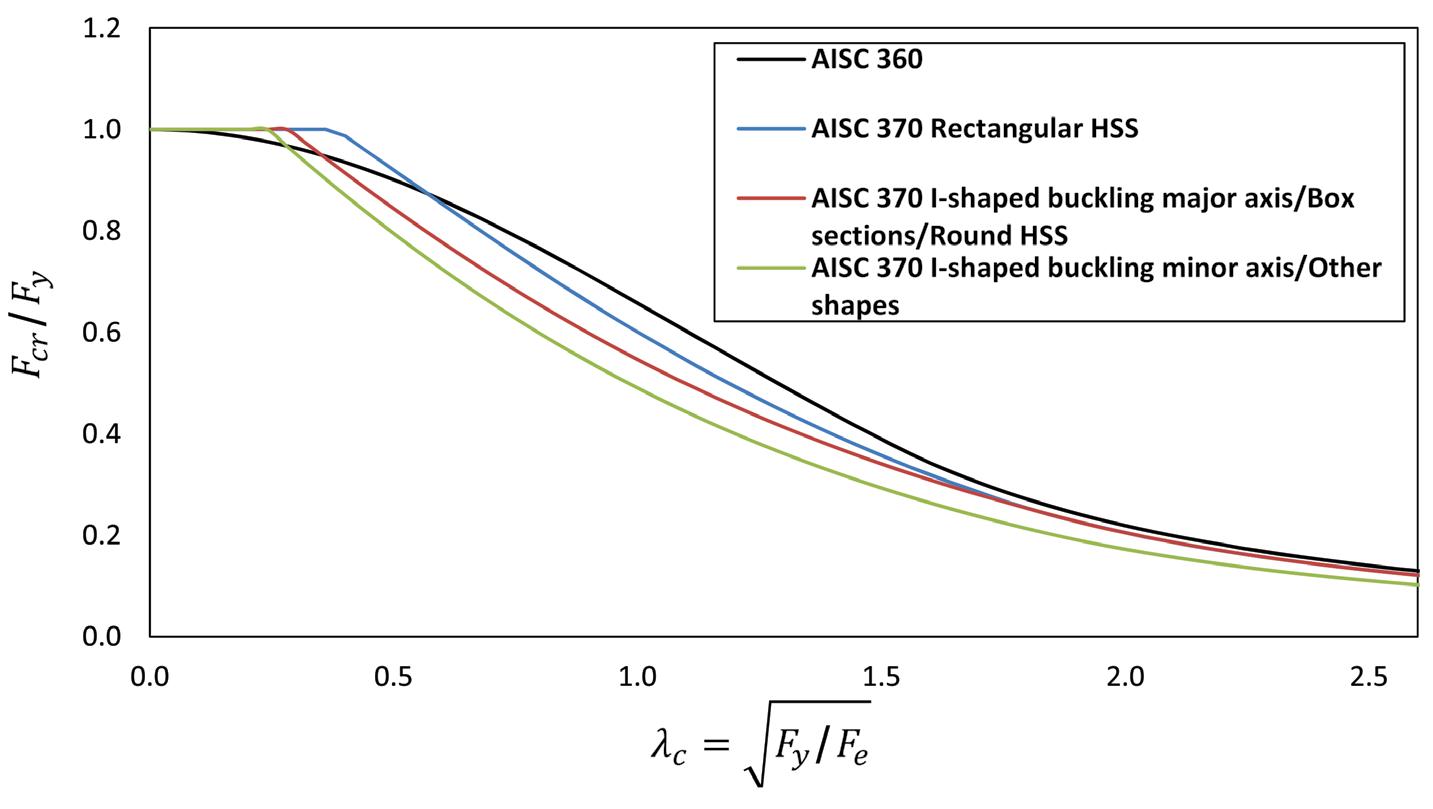
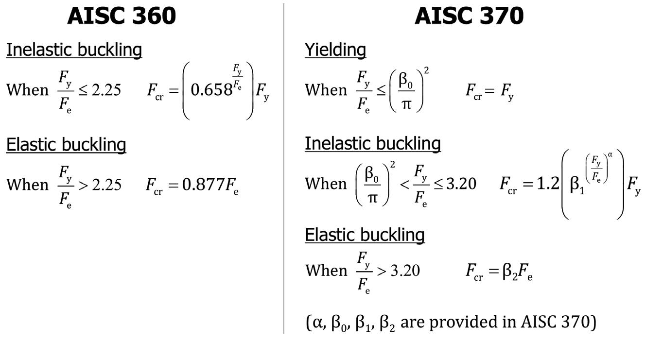
Buckling is a primary limit state for compression members, and as such, the design of compression members is affected by the non-linear stress-strain curve of stainless steel. At high slenderness (kL/r) values, column buckling is considered elastic and based on Euler buckling. Stresses in columns are generally low, and structural stainless steel columns perform about the same as corresponding carbon steel columns. At low slenderness, structural stainless steel columns can attain, and actually exceed, a yield load due to the beneficial property of strain hardening. (This is sometimes called the squash load, which is probably a better description because stainless steel experiences strain hardening that increases the strength as strain increases.) In the intermediate slenderness range, column buckling is in an inelastic range, and stainless steel columns have less capacity than correspond ing carbon steel sections (Figure 2). By no means does this imply that stainless steel is not appropriate for columns.
In AISC 370, there are separate column buckling curves for I-shaped sections buckling about their minor axis, for I-shaped sections buckling about their major axis and round HSS, and for rectangular HSS (Figure 3, page 18). Coefficients allow the use of a single set of equations for these three conditions.
The two main differences between AISC 360 and AISC 370 for flexural members are lateral torsional buckling (LTB) and local flange buckling. This is expected because the non-linear stress-strain curve for stainless steel affects limit states based on buckling.
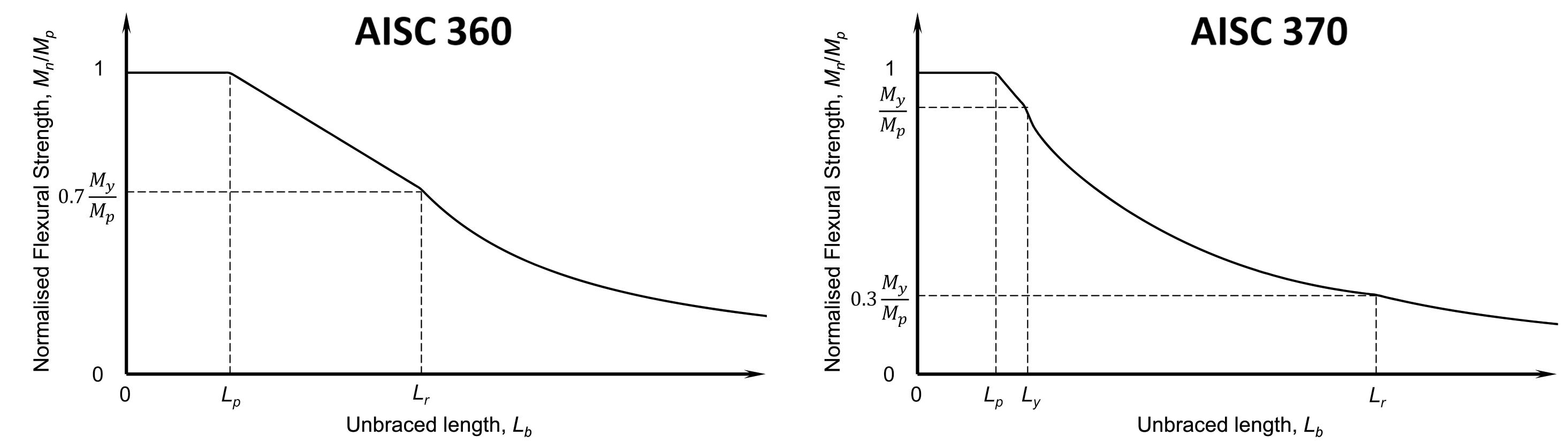
For compact I-shaped members or channels (members with no local buckling of the web or flanges), AISC 360 has one buckling curve comprised of three parts. For an unbraced length less than Lp (the length at which yielding of the entire cross-section occurs, or the length for which LTB does not occur), LTB does not govern, and therefore the flexural strength of the beam is given by the plastic moment. For unbraced lengths larger than Lr (the maximum length at which inelastic LTB occurs), LTB is completely elastic. For carbon steel, Lr corresponds to 0.7My/Mp (Figure 4, page 18).
For stainless steel, AISC 370 has separate buckling curves for austenitic and duplex stainless steels, and each curve is com posed of four parts. For an unbraced length less than Lp, the beam can reach the plastic moment, the same as for carbon steel. Then, the curve enters the inelastic region and decreases linearly to My at an unbraced length Ly. The second part of the inelastic LTB range goes from Ly to Lr Notice that the inelastic region between Lp and Lr in AISC 360 for carbon steel is a straight line. This region is a curve in AISC 370 for stainless steel because of the non-linear stress-strain curve. For unbraced lengths larger than Lr, LTB is con sidered elastic, just like carbon steel. However, Lr corresponds to 0.3My/Mp for stainless steel, which moves Lr much farther out. The design will rarely be in this range.
For I-shaped sections and channels with non-compact webs, AISC 370 uses the same approach as AISC 360 with a web plastifica tion factor. No standard carbon steel sections
with Fy less than or equal to 70 ksi have non-compact webs. Similarly, there are no corresponding sections with non-compact webs in austenitic stainless steel. In duplex stainless steel, there are only about a dozen corresponding sections with non-compact webs. The equations in AISC 370 for LTB of sections with noncompact webs are quite similar to those in AISC 360, modified to reflect the differences in material proper ties and non-linear stress-strain curves.
Flange local buckling of slender flanges is one of only a few areas where the design methodology in AISC 370 differs from that in AISC 360. In AISC 360, the capacity is based on the elastic local buckling stress of the compression flange without consider ation of post-buckling capacity. The flexural buckling strength is considered reached when the stress in the compression flange reaches the elastic local buckling stress. This approach is conservative because it does not account for the post-buckling strength. For this reason, it was decided to use the effective width method in AISC 370, where the effective width of the compression flange is used to calculate an effective section modulus. Flange local buckling is only applicable for non-compact and slender flanges. In AISC 360, this applies to ten standard carbon steel sections. For austenitic stainless steels, there are only about three corresponding sections that would have non-compact flanges. Remember that very few hot-rolled standard sections are available in stainless steel. Flange local buckling needs to be considered for custom-built-up sections. For duplex stainless steel, as with higher-strength carbon steels, more corresponding sections have non-compact flanges because of the higher yield strength.
Chapter G is the only place where the table of contents of AISC 370 differs from that of AISC 360. In AISC 360, torsion is in Chapter H with combined forces. Torsion was moved to Chapter G in AISC 370 because it is more of a shear consideration. The provisions for torsion are the same as in AISC 360 and include specific requirements for closed sections (round and rectangular HSS and box sections) subject to torsion. The Commentary for AISC 360 refers to AISC Design Guide 9 Torsional Analysis of Structural Steel Members for open sections sub ject to torsion. Design Guide 9 can also be used for open stainless steel sections included in AISC 370. (It is best not to use open sections for torsion due to low torsional stiffness and large deformation.)
Generally, the provisions for shear in AISC 370 are the same as those in AISC 360, except the web shear strength coefficients are different to account for the non-linear stress-strain characteristics.
For example, for sections other than round HSS or pipe, the web shear buckling coefficients, Cv1 or Cv2, can be as high as 1.2 to take advantage of stainless steel’s beneficial strain hardening characteristics. The expressions for the shear strength of round HSS differ from those for carbon steel, but they are based on the same design principles.
Chapter H of AISC 370 is taken from AISC 360 without modifi cation. The difference in the behavior of stainless steel members is already included in the strengths obtained from Chapters D, E, F, and G of AISC 370, so no change is necessary when combining the effects of different forces.

AISC 370 is a new design specification for hot-rolled, extruded, and welded stainless steel sections. It is adapted from AISC 360 and modified to reflect the difference in behavior between carbon steel and stainless steel. A few things from AISC 360 are not currently covered in AISC 370. However, it is not appropriate to use AISC 360 as a substitute for conditions not included in AISC 370. Work on AISC 370 is ongoing, and the next edition in 2027 should cover more situations.
■
 By Eytan Solomon, P.E., LEED AP
Concluding our series on automation – December 2021 (Installment 1), March 2022 (2), June 2022 (3), September 2022 (4) – I sat down (virtually) in July 2022 with two more industry experts in innovation: Dr. Erica Fischer, Assistant Professor of Civil Engineering at Oregon State University; and Ilana Danzig, Associate Principal at Aspect Structural Engineers. Below are highlights from our discussion.
You two were on a panel at the Structures Congress about innova tion within the AEC sector. Erica, you alluded in the panel to efforts at your university for corporation-funded research. Do you think that is a growing opportunity for innovation in the future? What motivates corporations to support that innovation?
Erica Fischer: Corporate-funded research through the university can occur in several ways. One method is where a consortium of companies come together, pull money, and sponsor research to see something come out of it. There is one within the College of Engineering called the Cascadia Lifelines Program, where a lot of the utility firms from around Oregon are sponsoring research regarding seismic mitiga tion on utilities and how to get their utilities ready for the Cascadia Subduction Zone earthquake. There is another one that Ilana is familiar with, which is called the REACTS consortium. It is through the TallWood Design Institute, which is Oregon State University’s College of Engineering, College of Forestry, and the University of Oregon’s College of Design. It fosters innovation and is an interesting way of ensuring the latest knowledge is getting directly into practice. We, as professors, get to see what is being used in the industry and where their challenges are. And then, on the flip side, the industry professionals get to be involved in research and be able to partner in the development of this new data, this new knowledge, and also help
with the mentorship of the graduate students. And, maybe because it’s the Pacific Northwest, we see more industry-sponsored research on mass timber. We see a lot more collaboration across structural engineering companies in mass timber. I also think the younger generation of researchers and engineers are just more comfortable in the collaborative space than keeping information to themselves.
Ilana Danzig: I agree. In this field, not much hoarding of knowledge is possible because once you produce a design that gets built, it is out there and open to inspection for anyone who wants to see it and learn from it. Usually, we accept and invite that we are all looking at what everybody’s doing and building off what we see. This is because all structural design grows out of past innovation. It is why creative engineering is not about solving any one particular problem: it’s about the innovative approach to solving problems so we can make incremental progress together as an industry.
Ilana, you made the great observation on the panel that “innovation needs space for failure.” But, of course, there’s a tension between that and the fact that structural design projects like a building or bridge are usually single instances, or as Zak Kostura put it in my first session, “we’re expected to make a profit for the owner on a first prototype.” So how and where do we find that space for innovation, i.e., space for failure?
Ilana Danzig: First and most importantly, there needs to be room for failure within the group you’re working with and collaborating with internally – it starts with colleagues. There needs to be room to explore ideas and make suggestions, even bad ones, that can get debated and discussed, and you need to be allowed to get it wrong. But, even on a project team, if the team’s shared goal is innovation, the team must have space to explore a path that might lead nowhere. That process has to be done within limits – most clients are not OK with signing a blank cheque for a pro totype that is thrown out, for example. But in solving novel problems, there must be a culture of trust, where challenging each other on key ideas is expected, and the best ideas can be surfaced. Otherwise, everyone’s protecting themselves the whole time, and you don’t get anywhere. There is no real growth and learning without space for this, but you need trust within the team, and you need a shared goal of trying to innovate toward a tangible outcome.
Erica, your research includes numerical modeling approaches for steel and composite structures and con nections. Do these approaches employ automation tools?
Erica Fischer: We are setting up numerical methods for automation, just as we see in industry. In academia and research, we are examining how to link different computer simulation tools together such that the research is more

I think that’s the greatest part about structural engineering today: we have tools to automate the simple and repetitive, which frees us up to dig deep into the challenging and creative (the fun parts)!
Ilana Danzig
streamlined. We accomplished this by linking BIM with a fire dynamics simulator so that we could look at building fires in different stages of construction. Still, there are many other examples of researchers who are doing this. Regardless of the automation we are employing in the research or in industry, it all has to be validated and verified through our more traditional analysis measures; otherwise, you can get whatever you want from these computer simulations.
Ilana, you alluded to your work with CLT box modules in the panel. Do you employ automated design tools for those projects?
Ilana Danzig: Here is what I have found on mass timber projects, especially on this volumetric modular work: Automation helps us shortcut to the meat of the problemsolving. It is relatively easy to create a program or tool to set up a model based on input parameters and do a bunch of basic analyses that can spit out member sizes, maybe with some material optimization. That’s an easy problem to solve. The hard problem is how do we put it all together? How does the system work for connections, transportation, lifting or fire requirements, and so on? There’s so much more to structural design than sizing members, and computationally speaking, sizing members is the simplest thing we can do and automate. But that barely scratches the surface of the design and coordination required on these volumetric modular projects. The juicy part of these prob lems is solving how it works together as a system, and that’s where we still need human creativity, problem-solving, and intense multidisciplinary collaboration. We need to zoom out a little bit, zoom in really close to a connection, and then zoom out again. It is a dynamic and creative process.
Erica Fischer: To add to that, we’ve been performing volumetric modular research here with mass timber, and I think if you are going to look at panelized and modular buildings versus beam-column volumetric modular (e.g., steel modular), these are two different animals. Panelized systems are often these flat-pack operations: how do we flat pack it out to the site and pop it up for rapid construction? But then, specifically, when getting into high-rise buildings, there are still questions such as: what are the implications of having a rigid diaphragm versus a flexible diaphragm, because you can have either in a mass timber building. What are the implications and demands on intermodular connections (module-to-module)? How do you create a continuous diaphragm?
Modular buildings tend to have first-story mechanisms, so how do we design our mass timber modular buildings so that we don’t have a first-story mechanism? I can go on and on with the issues; there are still so many questions. But unfortunately, the research on high-rise mass timber buildings is in its infancy, and we don’t even have the answers to many of these questions.
Ilana Danzig: And I think that’s the greatest part about structural engineering today: we have tools to automate the simple and repeti tive, which frees us up to dig deep into the challenging and creative (the fun parts)! Figuring out how much volume of wood is in a mass timber building, a prefab building, or a modular building is a relatively easy task. The move into offsite-prefabrication and modular systems is really about the speed of construction: how efficiently buildings can be delivered and whether you can get all the different parts to work together within a system. It’s a new frontier and a quantum leap away from just material takeoffs.

Could you envision that someday, many years in the future, those parameters about constructability, fire design, and so forth can get understood and codified and laid out into computer code, so it does approach automation?
Ilana Danzig: Yes, and then we will solve new and different prob lems. After the creative and collaborative work of system development comes the opportunity to automate design. In fact, for individual systems, that is already happening now. Once a modular system is developed with reasonable confidence, we have the system’s rules, which can then be automated for further use in future builds. Some of those rules will come from code updates, like fire requirements for concealed spaces and diaphragm design, and sometimes those rules are from testing or engineering analysis. Either way, the system design establishes a set of rules to essentially get the designer out of the way so production can happen. This is a simplification, of course, but I think that is what’s interesting and different about this manufactur ing approach to buildings: It separates design into development and production, and we, as structural engineers, are not used to think ing like that; it is a paradigm shift. Design is not something that is easily automated, though tools can help. But production could and should be automated, even on the engineering side. Of course, the real gains of modular work are the automation opportunities at the fabrication and construction levels. The savings on design are quite small relative to that.
Ilana Danzig: In the Structures Congress panel that Erica and I were on earlier this year, someone referenced the airline industry and the kind of advances in automation that happened in that industry. Those kinds of advances haven’t happened in the buildings industry yet, but many companies and groups are putting much effort towards getting there, and I think off-site and modular are going to form part of those major advances. Along with the more common and expected advances in building heights and technologies, I think there’s a shift coming to automating at a building level. Still, it is not a shift that will impact all buildings and all structural designs. However, I believe it will change how we think about design for standard and repetitive types of projects like low-rise multifamily, student residences, hotels, etc. I’m curious to see how that progresses over the next 10 years,
I think we will begin to see automation to make building design and construction more affordable. There’s automation that desperately needs to happen for our industry to be more efficient and for us to deliver more reasonably priced products.
because over the last 15 years, I have watched how design has changed and sped up amazingly with the software tools and the automation we have. And the result of this speed-up has not been that engineers aren’t needed anymore or as much. Instead, the results seemed to be that engineers are used more for problem-solving than pure analysis and computation.
Erica Fischer: I think we will begin to see automation to make building design and construction more affordable. ere’s automation that desperately needs to happen for our industry to be more efficient and for us to deliver more reasonably priced products. As a profession, we could be more integrated. However, I think we will always need an engineer to oversee a lot of this automation. We saw the emergence of Katerra and the failure of Katerra, but I don’t think we should see this as a failure of our industry. Let’s see this as a success that someone tried to disrupt it. It got people thinking. [Katerra was an American technology-driven off-site construction company founded in 2015 and filed for bankruptcy in 2021.]


When I graduated from my undergraduate studies, everyone wanted to design the next tallest building. Now, if I give seniors in my class a survey on the first day and ask them what their career goals are: out of approximately 80 students, maybe one will say they want to design tall buildings. Most everyone else is thinking about societal issues.
at’s where their passion lies. We see this echoed in our professional societies at conferences and webinars. ere are many more presentations and webinars about simulating a whole community. We, as structural engineers, are bridging the gap between the traditional engineer, technical knowledge, and larger society. Ilana Danzig: Sustainability is also a huge part of the conversation now. I see more and more that it’s a major driver for new grads who join us. As structural engineers, we have an enormous opportunity for positive impact in many more ways than traditionally thought. And looking at those newly graduated and the issues they care most about, I have a lot of hope for the social and societal role we engineers can and will play.■


It’s interesting. I started this series with the theme “automation and the future of structural engineering,” but where we’ve ended up is “the human factor and the future of structural engineering.” If the engineer working on a project feels ownership of the project and is passionate about it, that is the best chance for success: It’s not about just putting the numbers into

the computer and seeing what gets spit out. Instead, it’s taking the care to look at load path, complex connections, coordination, and so forth: the “non-computable” things that sometimes get missed.
I want to thank Erica, Ilana, and all the past interviewees of this series, for giving their time and insights. I hope our readers feel better prepared and inspired about the exciting future of our profession. Don’t hesitate to contact me or STRUCTURE magazine if you want to share your thoughts!
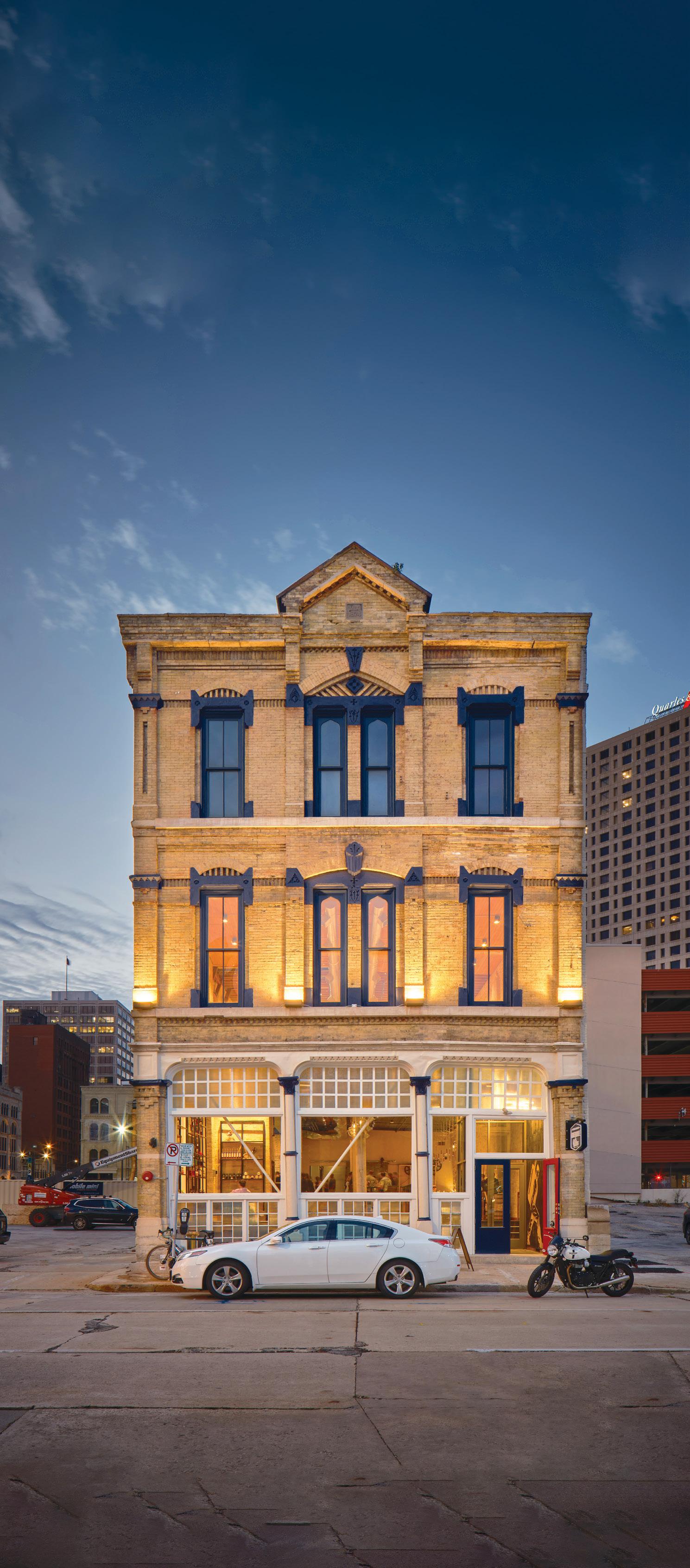
Historic buildings draw us in with their character and sense of history. Cracks and imperfections are part of the appeal. But what happens when the quirks are not just superficial but indicators of significant structural distress? For Central Standard Craft Distillery, a Milwaukee-based company that purchased an 1874 building, the answer was to implement a top-to-bottom structural retrofit that would preserve the charm while also making the building safe to occupy. In January 2020, national interdisciplinary design firm HGA joined the mission to renovate the 16,000 square-foot, three-story building to create space for a bar, restaurant, tasting room, events space, and rooftop patio to promote Central Standard’s growing business. Originally designed by renowned Milwaukee architect Edward Townsend Mix, the building’s condition had worsened over the years due to foundation settlement and deficiencies in the original engineering design. Floors that were originally flat now sloped as much as 15 inches over 60 feet, while brick walls leaned to the west by as much as 6 inches per story.
e structural retrofit would include micropilesupported foundations, masonry shear walls, steel bracing, and plywood diaphragm reinforcement. No attempt was made to lift and straighten the building. Instead, the effects of the leaning walls and sloping floors would be accounted for by HGA in the structural design. Finding locations for the new shear walls and bracing was difficult as the architectural plan called for open spaces with the existing brick and timber framing exposed prominently. e engineering team’s solution for concealing the new masonry shear walls was to integrate them into the stair and elevator enclosures. Where visible repairs were inevitable – such as the steel X-bracing at the windows of the street façade (Figure 1) – HGA chose solid bar bracing over steel tubes to minimize the visual impact. Installation of the structural repairs by the general contractor, Gardner Builders, also needed to be sensitive to the requirements for historic preservation. For example, existing wood flooring was carefully removed so it could later be reinstalled over the plywood diaphragm reinforcement.


 B Y B EN S HOCK , P.E.
To determine if foundation stabilization would be necessary, HGA excavated a test pit in December 2020 to examine the original foundations and assess their condition. ey discovered that in 1874, the builders used a system known as timber grillage, where brick and stone walls were built directly on a grid of timbers – similar in size to railroad ties but placed tightly together and oriented in two layers in alternating directions (Figure 2). Timber piles were not found in the test pit or any subsequent excavations. (It is the author’s experience that
Figure 1. Central Standard’s new building at 320 E. Clybourn St. in Milwaukee, WI. Courtesy of John Magnoski.
timber pile foundations are encountered more frequently under similar buildings in this area.)
Groundwater was encountered only 12 inches below the top of the basement slab, requiring the pit to be dewatered before the timbers could be inspected. The groundwater relates to the natural topography at the time of construction. In 1874, the project site was located at the transition between solid ground and a marshy area that was being infilled to create what is now called Milwaukee’s Historic Third Ward. It may seem coun terintuitive that untreated timbers can be used for foundation systems in wet areas. Yet, as long as the timber sections remain fully submerged, oxygen is driven from the wood fibers, and the oxygen-loving organisms that cause decay cannot survive.
The gradual lowering of the water table in Milwaukee over the past 150 years has caused many timber foundations in the area to dry out and experience decay, along with accelerated settlement. In these cases, foundation retrofit is typi cally cost-prohibitive, and demolition generally follows. The author feared that decay might be the cause of the settlement at Central Standard’s project. The test pit, however, revealed intact timbers. Instead, soil borings taken in January 2021 pinpointed the actual cause of the settlement – consolidation of the marshy, organic soil. Thus, the timber grillage foundation system was functioning as originally installed. However, its original design was flawed, and the organic soils could not support the weight of the building without excessive settlement.
Uneven vertical settlement of the foundations initiated a westward tilt in the building’s walls and columns. At the south façade, as shown in Figure 3, the horizontal displacement was noted between the sidewalk elevation and the top of the first story. The structure is primarily a rect angular brick box, except for the lower part of the street façade where no shear wall or bracing exists. The author imagined a con versation held in 1874 between the architect and the builder to discuss which was more important – building integrity or windows. The windows were obviously judged to be more critical, resulting in an incomplete lateral system. This needed to be addressed by HGA.
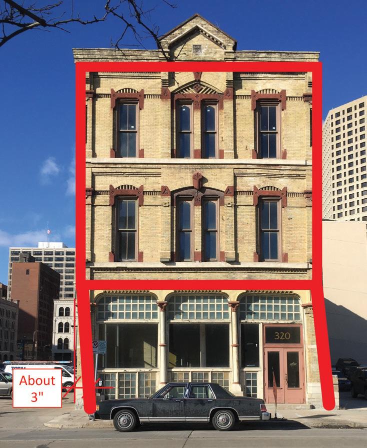
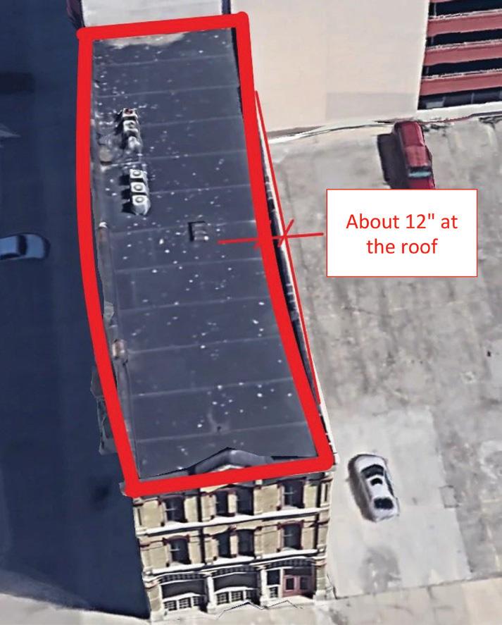
In addition to the displacement at the south façade, horizontal displacement also occurred between the north and south walls, as shown in Figure 3. Calculations by HGA revealed that the existing tongue-and-groove subfloor was severely under-designed in terms of dia phragm strength and stiffness and could not
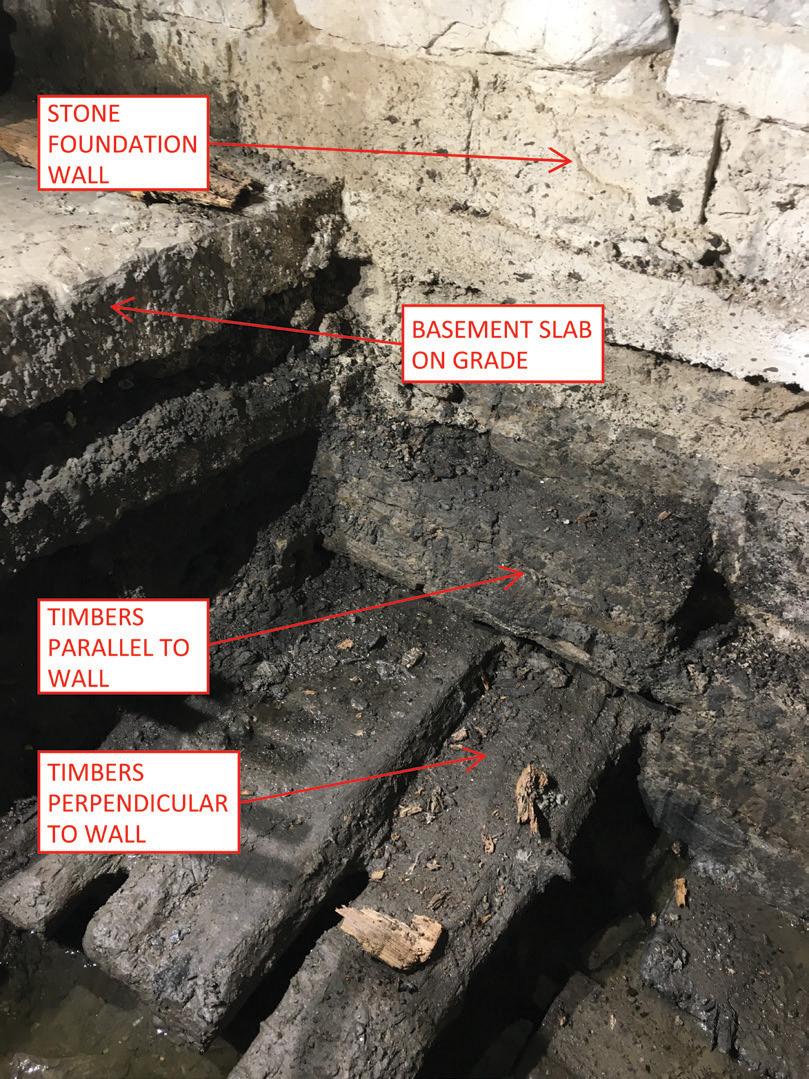
resist this horizontal movement. A stair was added in a 1990s renovation to meet fire-safety requirements, worsening the situation and further weakening each floor diaphragm’s integrity (Figure 4, page 24 ). The out-of-plumb condition of the existing brick walls was a significant concern. The massive weight of the leaning walls generated horizontal forces that exceeded the design wind loads. Calculations revealed that the building’s flawed lateral system could not even resist the required wind forces, so it was a mys tery how the building had survived for so many years in this condition. It became evident to HGA that significant upgrades to the lateral system would be needed.
The combination of wind load and horizontal forces related to the leaning walls meant that most components of the upgraded lateral system would be pushed beyond the range of what is typical for a building of this type and size. To increase diaphragm strength and stiffness, ¾-inch plywood was applied over the existing subfloor at each level. With a shear demand exceeding 1,000 pounds per foot, blocked diaphragm values with tight nailing patterns were required. Where the existing timber sub-floor was thick enough, HGA justified that it could serve as the blocking without the need to install 2x members under the floor. At other locations, the author detailed stapled sheet metal blocking, which could be installed entirely from the top side of the floor. Diaphragm chords were created at the long sides of each floor using laminated veneer lumber (LVL), purchased in 42-foot lengths to minimize splices.
As shown in Figure 4, an existing stair and non-functional cargo elevator blocked diaphragm access to the north wall. Although the
elevator was being upgraded to a modern system, it needed to remain in the same location. Similarly, relocating the stair would not be practical. HGA’s solution was to introduce a concrete masonry unit (CMU) elevator shaft and an additional shear-wall tight against the existing stair. All CMU walls were heavily reinforced – sometimes with two #7 bars in a single cell – requiring mechanical bar cou plers. Excavations were required under the basement slab to install micropile-supported foundations for support of the new shear walls (see next section). Carpenters modified the existing framing at each level to create space for the shear walls.
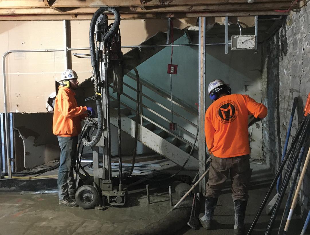
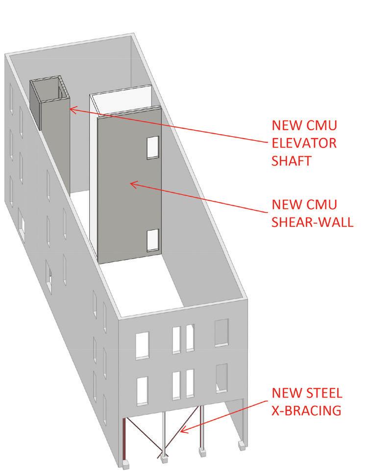
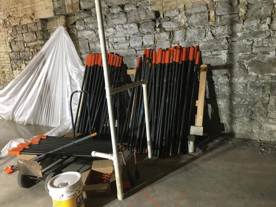
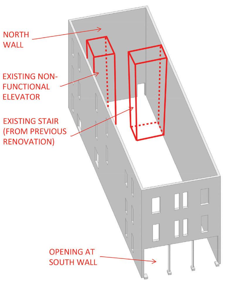
The last piece of the structural puzzle was to address the addi tion of bracing at the large opening in the south façade. Solid steel bars, 2¾ inch in diameter, were chosen along with matching clevises and turnbuckles to accommodate the horizontal forces while minimizing the braces’ visual impact. An HSS 10x6x½ was used at the top of the first floor to facilitate the connection between the braces and the existing brick wall above. The braces were anchored to a concrete grade beam in the basement, again supported by micropiles.
With a plan worked out to address deficiencies in the lateral system, HGA shifted its focus back to the founda tions. It was always known that the new walls and bracing would require concrete grade beams supported by micropiles but deciding what to do with the existing foundations was the subject of much discussion. HGA pre sented an option to the building owners, including a full retrofit of all timber grillage foundations using micropiles. This option, however, was judged to be cost-prohibitive and incompatible with the project schedule. Despite concerns about differential settlement between existing and new foundation compo nents, the project team decided that foundation strengthening should occur only at the steel bracing and new masonry walls.
This decision was judged to be acceptable for three main reasons. First, the exposed brick walls were in remarkably good condition and showed no signs of accelerated settlement or distress in recent years. The condition suggested to HGA that vertical and horizontal displacement had occurred at a slow and consistent pace. Secondly, though the engineering design of the timber foundation system was deficient, the timbers themselves were intact, and the system was functioning as initially constructed. Thus, any future settlement would follow the established trend. Finally, the last factor that influenced HGA’s strategy for foundation repairs was the intended life span, established by the building owners to be 20 years of occupancy beyond the completion of renovations.
Though the team believed that the structural retrofit would lessen the potential for further settlement and displacement, they adopted a belt and suspenders approach by designing the new lateral system to accommodate 20 years of future westward lean. Future move ment was estimated to follow the same trend as the displacement that had already occurred. A survey program was also established
to monitor the position of the leaning walls at regular intervals over the next 20 years.
A micropile is a reinforced grout column created by advancing a cutterhead into the soil while simultaneously injecting a highpressure cementitious mixture. Design and installation of the micropiles were performed by a specialty foundation contrac tor based on design parameters provided by the geotechnical engineer. A total of 45 micropiles were installed, each supporting 20 tons through both skin friction and end bearing at depths of up to 80 feet below the basement slab. Reinforcement for each micropile was provided by a 1½-inch diameter hollow steel bar, which also served as the shaft for the cutter head and a conduit for the grout pumped to the bottom of the excavation during installation.
Micropiles were selected for the deep foundation system primarily because they can be installed with minimal overhead clearance. The hollow steel bars were supplied in 4-foot lengths (Figure 5) and spliced using threaded couplers.
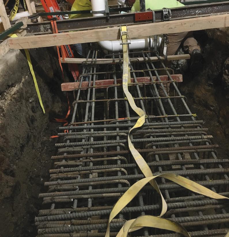
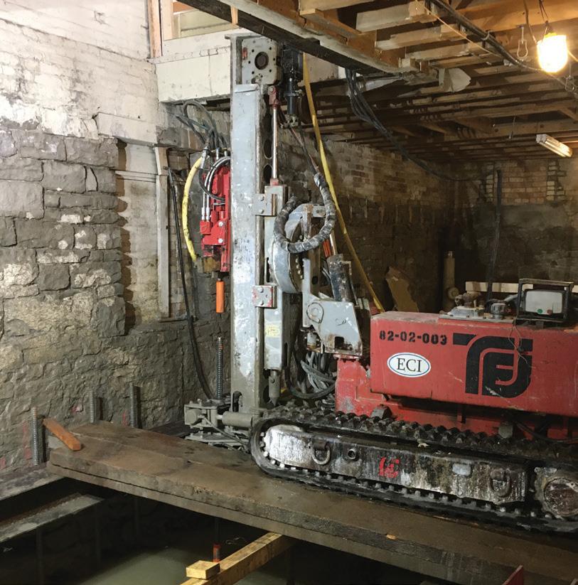
Advancing the cutter head into the soil required a counteracting force on the top side. In most cases, the existing basement slab was used as the anchor for a portable installation rig. Holes were first coredrilled through the existing slab at the micropile locations, and the
rig was then bolted to the slab above each location in turn. Figure 6 shows this process. When all micropiles in an area were completed, the existing slab was removed. Next, a concrete grade beam was constructed around the exposed tops of the micropiles (Figure 7 ). At the location of the new elevator pit, where no slab was available for anchorage, a heavier track-mounted drill unit was used (Figure 8). This machine’s self-weight counteracted the upward reaction caused by the micropile installation.
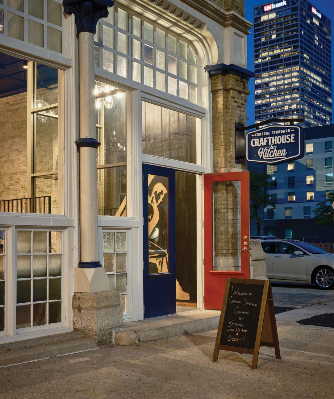

HGA’s structural retrofit was critical in transforming a neglected, historic building into a vibrant – and safe – local destination. A successful outcome was achieved through practical structural solu tions as well as respect for the historic nature of the building. The building’s unusual shape was not adjusted or straightened; rather, it was preserved in its current condition, with the leaning walls accounted for in the upgraded lateral system. The project demon strates that adaptive reuse of a historic building can be cost-effective and schedule-friendly while delivering authentic charm and character that would be difficult to reproduce in a new build. Please perform a structural inspection of your own (during happy hour, of course) if you are in the area.■
(bshock@hga.com).


1.
The new Massachusetts Bay Transportation Authority (MBTA)
Iron Horse Park Operations Control Center (Figure 1) is designed to house dispatching and administrative operations for the MBTA north-side commuter rail system and the dispatching operations of the system for a commercial freight rail operator. The new 24/7 missioncritical facility features a clerestory that allows abundant natural light into the primary dispatching area, a state-of-the-art video wall, and doubly redundant MEP systems to protect against single points of failure. The challenges associated with constructing this essential facility on a site that could liquefy in an earthquake were identified early and drove several decisions regarding the ground floor level and foundation system. The MBTA selected Simpson Gumpertz & Heger, Inc. (SGH) to lead a multi-disciplinary design team for the design of the new facility. SGH served as the project’s Structural Engineer of Record (SEOR).
The building is a steel braced frame structure on reinforced-concrete grade beams and pile caps supported by steel H-piles driven into glacial till. A steel deck carries diaphragm loads at the low roof and high roof levels, and a concrete slab on metal deck serves as the elevated secondfloor diaphragm. A two-way reinforced concrete structural slab at grade that spans between grade beams carries diaphragm loads at grade.
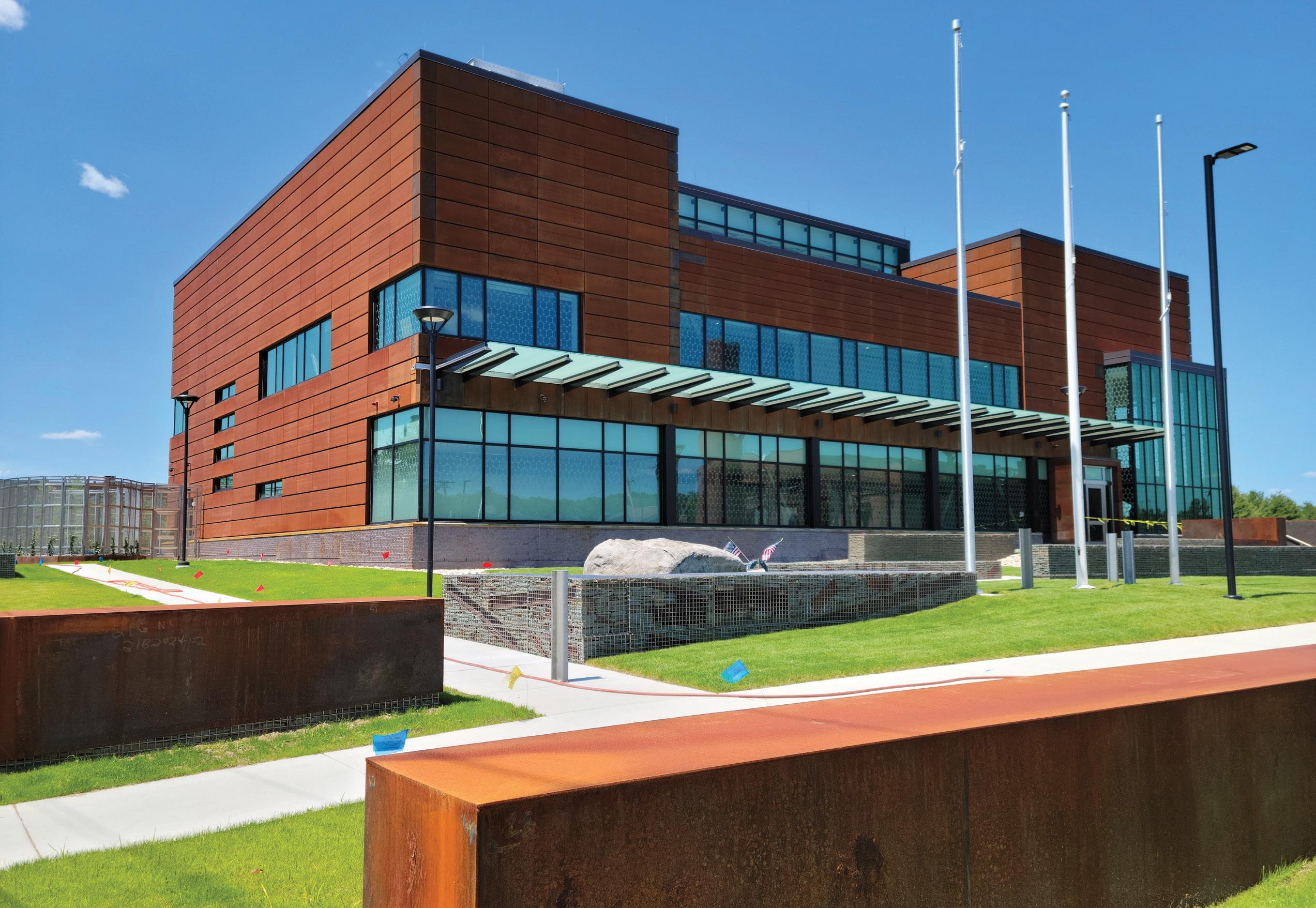
Developed in the early 20th century, Iron Horse Park originally served as a locomotive repair complex for the Boston and Maine Railroad.
When the railroad purchased the land, site topography varied in elevation by up to 10 feet, it contained a small brook and swamp area, and the Old Middlesex Canal traversed it. The canal was diverted to make way for the expansive railroad facility, and the land was cut and filled to create the near pancake-flat site that exists today. Over the years, regular railroad operations gave way to its use as a large industrial complex by several different companies. Operations on the site resulted in soil, groundwater, and surface water contamination and its designation as a Superfund site by the United States Environmental Protection Agency in 1984.
Iron Horse Park is quieter than it used to be, but its railroad legacy lives on. Multiple parcels are now owned by the MBTA, and freight is still delivered to the site by rail. As the MBTA and the freight operator dispatch trains on shared tracks, Iron Horse Park was identified as an excellent location for a new shared dispatching facility. While the advantages of constructing at this site were quite apparent on the surface, several challenges lurked below grade.
Nobis Group of Lowell, MA, completed a subsurface geotechnical investigation at the proposed building and parking lot site in 2017. The program consisted of ten borings, all terminating in glacial till or bedrock. The general subsurface profile consists of (top to bottom) a thin layer of granular fill, very loose to medium-dense native granular soils, medium dense to very-dense glacial till deposits, and bedrock
(Figure 2). Groundwater was encountered from 1.8 to 3 feet below the ground surface. The granular soil layer includes a layer of saturated loose sands with minimal fines and Standard Penetration Test (SPT) blow counts (corrected to a hammer energy of 60%) as low as 4 blows per foot (bpf) and as high as 34 bpf.
Nobis Group completed an SPT-based liquefaction analysis using the Idriss and Boulanger procedure for each of the borings under neath the building. It determined that the soil profiles in four of the five borings underneath the building footprint include layers of soil susceptible to seismic-induced liquefaction ranging from 13 to 22 feet thick. Seismic-induced site settlement of up to 10 inches is predicted in the event of a maximum considered earthquake (MCE) (an earthquake with a 2,500-year return period). Nobis also identified that the liquefaction settlement would result in a significant down drag on the piles.
Minimum Design Loads for Buildings and Other Structures (ASCE/ SEI 7-10), Section 20.3, requires that sites with liquefiable soils be classified as Site Class F and that a site response analysis be performed following Section 21.1 unless the structure has a fundamental period of vibration equal to or less than 0.5 seconds. The Commentary to ASCE/SEI 7-10 indicates that “ground motion data obtained in liquefied soil areas during earthquakes indicate that short-period ground motions are generally reduced in amplitude because of liquefac tion, whereas long-period ground motions may be amplified by liquefaction.” After some strategic stiffening of the structure, SGH computed a period of 0.47 seconds for the building. Although a site response analysis was not required, the team still needed to assess and address liquefaction potential as a geologic hazard.
Site Class D would be applicable had liquefaction not been a concern. For this site class, the design seismic parameters are SMS equal to 0.371g, SM1 equal to 0.175g, SDS equal to 0.25g, and SD1 equal to 0.12g. The peak ground acceleration (PGAM) for the MCE is equal to 0.20g, which is used to determine the liquefaction potential. The seismic design parameters and the risk factor resulted in a seismic design category (SDC) of C.
The design team initially contemplated using ground improvement by installing rammed aggregate piers under the building footprint. This method would improve bearing capacities, reduce the risk of liquefaction by densifying the underlying soils with columns of compacted stone, and enable the use of shallow foundations and a conventional slab-on-grade. Ground improvement proved to be a fea sible alternative to a deep foundation system. However, the projected cost savings were not significant, so the MBTA elected to pursue a more conventional driven pile solution to minimize disturbance to
the underlying potentially contaminated soil and groundwater. The building site is elevated approximately 6 to 7 feet above the surround ing grade to provide resiliency against the projected 100-year flood. Therefore, all building-related pile cap and grade beam excavation would occur in uncontaminated fill.
Ultimately, the foundation design included a conventional deep foundation system consisting of steel H-piles driven to glacial till or bedrock, reinforced concrete pile caps and grade beams, and a reinforced concrete two-way structural slab at grade. The selected foundation system mitigated the building’s susceptibility to settlement in an earthquake but did not address the liquefaction potential of the underlying soils. Liquefaction of the saturated clean sand layer can cause unbraced lengths of 22 to 26 feet. However, the HP14x73 piles have adequate strength to support applied axial loads for the unbraced lengths. Next, confirming that the foundation system could maintain lateral stability during an MCE-level earthquake was necessary as the soil profile moves horizontally in different amounts between the top and bottom of the unbraced lengths.
For the pile system’s lateral stability analysis, SGH conservatively assumed that the potential soil liquefaction would result in a 25-foot unbraced length for all piles. Next, the rotational fixity of the piles above and below the potential unbraced length was determined. The 2015 International Building Code (IBC), Article 1810.2.1, permits the assumption that piles are laterally supported 5 feet into stiff soil or 10 feet into soft soil. All piles are expected to develop full fixity at their base due to the requirement to drive piles a minimum of 5 feet into glacial till. However, full rotational fixity within a stiff soil layer is not assured above the potential unbraced length.
Therefore, eight piles near each corner of the building (32 piles total) are extended 20 inches into the pile cap to obtain rotational fixity at the top of these piles (Figure 3, page 28 ). Rotational fixity is obtained as a horizontal force couple develops between the top and bottom of the embedded por tion of the pile (Figure 4, page 28). The approach is described in the U.S. Army Corps of Engineers, Report No. CERL TR M-339, Fixity of Members Embedded in Concrete. Although the general recommendation from this reference is to embed the pile two times the pile depth into the pile cap, the design team was able to reduce the embedment by specifically design ing for the fixity. For pile caps providing pile fixity, reinforcement is specified near the bottom of the pile cap and a few inches above the top of the pile to spread the forces of the force couple. Grade beams prevent the pile caps from rotating. Where necessary to transfer the moment demand from the top of piles to the grade beams, the pile caps are designed for the torsion between the moments transferred from the piles and the rotational restraint provided by the grade beam. The analysis considered these 32 piles acting as a group to maintain the stability of all piles during liquefaction.
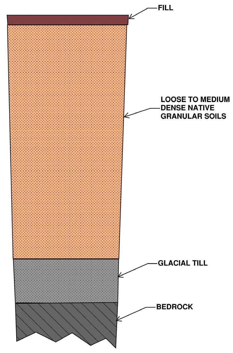
Figure 3. Foundation plan shows piles with fixed tops (blue pile caps) and pinned tops (yellow pile caps).
An estimate of the amount of differential movement between the top and bottom of the unbraced length of piles is required to deter mine the stability of the system. The movement can be estimated if the applicable spectral acceleration and period are known. Although the period of the pile system was not known, it could be conserva tively assumed to be long. Using the transition period between the constant velocity and constant displacement portions of the design spectrum (TL) is sufficiently long because the expected displacement will be similar for longer periods. TL is equal to 6 seconds for the site, as obtained from Figure 22-12 of ASCE/SEI 7-10. The maximum spectral displacement for the MCE-level earthquake was computed using the known relationship between the spectral acceleration and spectral displacement for an undamped oscillating system.
• Spectral acceleration, Sa (at TL) = SM1 / TL
• Circular frequency, ω (at TL) = 2π / TL
• Spectral displacement, Sd (at TL) = Sa / ω2
For TL equal to 6s, SM1 equal to 0.175, and Sa equal to 0.029g, a spectral displacement of 10 inches results. Therefore, 10 inches was used as the maximum displacement with the seismic weight of the building and foundation structure to complete a P-delta analysis for the pile group. First, the shear demand on the group of fixed-fixed piles was computed and compared to the shear demand against the pile group’s shear capacity. SGH calculated the pile group’s shear capacity as the sum of the plastic moments at the top and bottom of the unbraced pile length accounting for the supported axial load divided by the unbraced pile length. Subsequently, the stability coefficient of the pile group was determined using ASCE/ SEI 7-10 Equation 12.8-17. The resulting stability coefficient of 0.18 was less than Θmax. Therefore, the foundation system would remain stable in the event of seismic-induced liquefaction during an MCE-level earthquake.
The potential for seismic-induced vertical settlement of 10 inches also had non-structural implications. For example, utility lines entering the building are ground-supported and could fracture near
the interface with the pile-supported build ing if the predicted settlement occurred. Therefore, the design specified specialty flexible expansion joints at the building interface for critical utilities to accom modate this potential movement. While relatively common on the west coast, the use of this product was unique enough to require a variance from the Massachusetts Board of Registration of Plumbers and Gas Fitters.
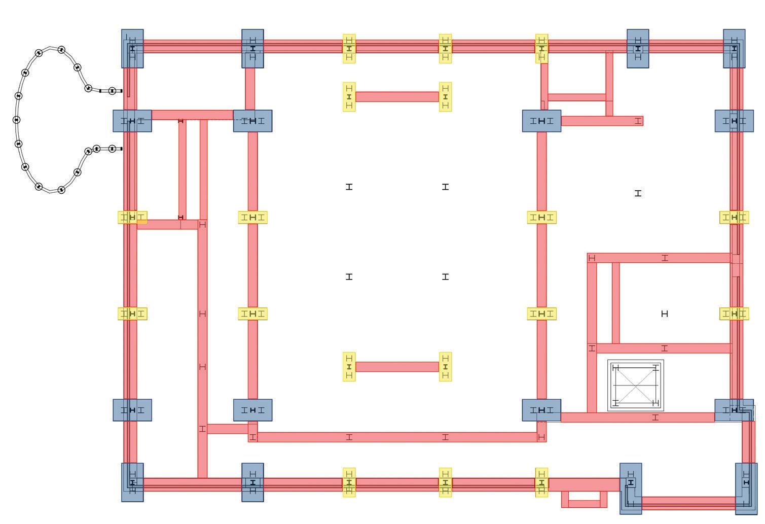
Construction of the Iron Horse Park Operations Control Center is nearing successful completion. This essential criti cal facility is constructed on a site with geotechnical challenges that are unusual considerations for much of the United States. Accounting for the predicted seismic-induced displacements requires consideration of how they affect not only the building superstructure but also the foundation system and utili ties. The practical approach taken to address the foundation design resulted in a building that will be ready to continue operations in a very rare earthquake.■

References are included in the PDF version of the online article at STRUCTUREmag.org.
All authors are with Simpson Gumpertz & Heger, Inc., Waltham, MA.
Jason C. Varney is a Senior Consulting Engineer (jcvarney@sgh.com).
Jake E. Hughes is a Consulting Engineer (jehughes@sgh.com).
Dominic J. Kelly is a Senior Principal (djkelly@sgh.com).
Figure 4. Geometry and load path of the schematic pile cap. The blue arrow indicates the direction of movement, and the red arrows indicate the force couple developed for pile fixity. Closed stirrups (perpendicular to the section cut) are provided to resist torsion due to perpendicular grade beams (not shown).
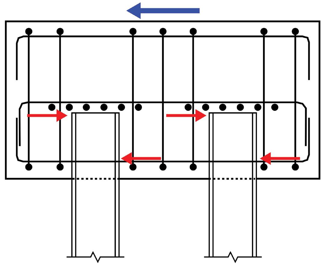
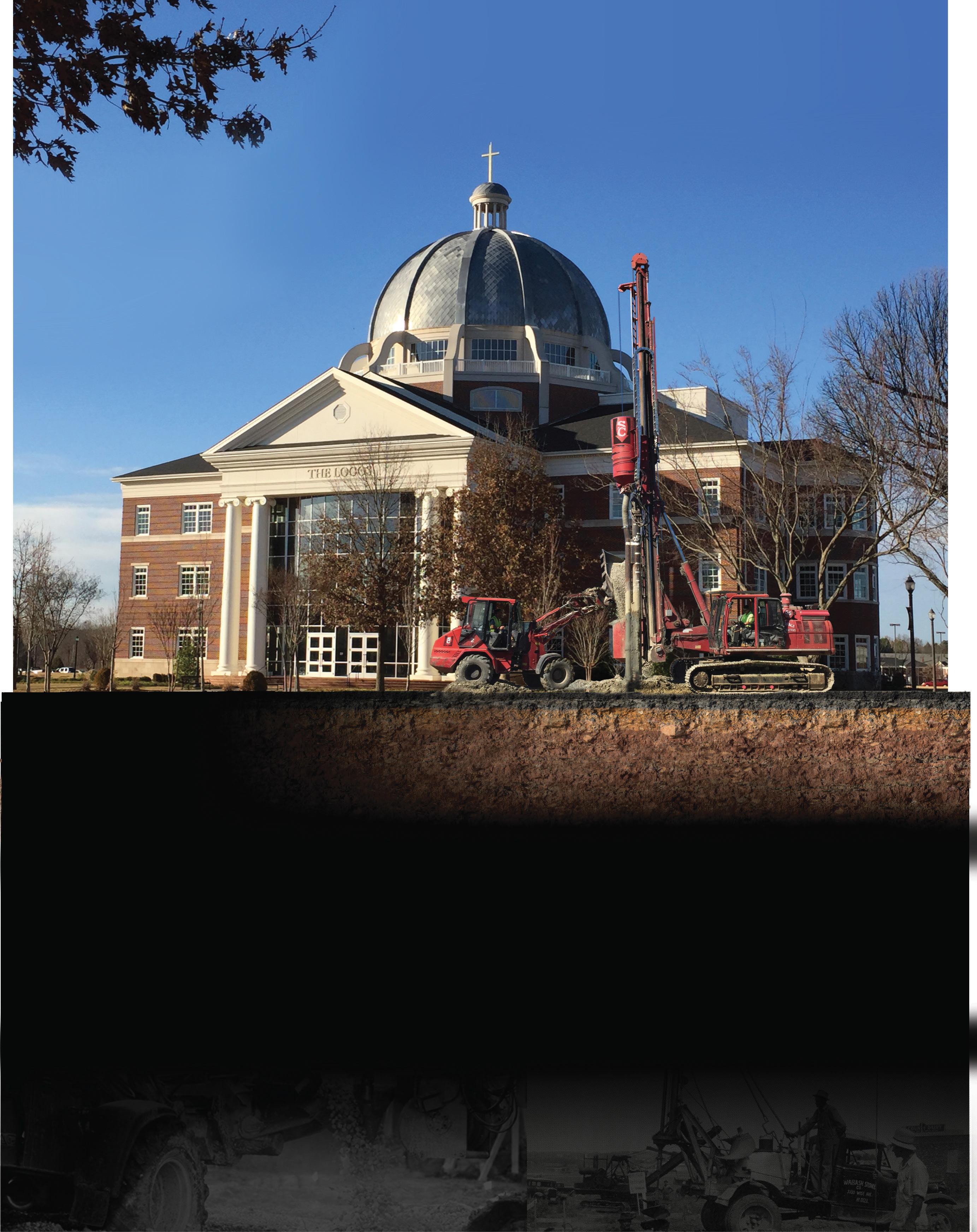

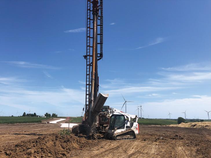

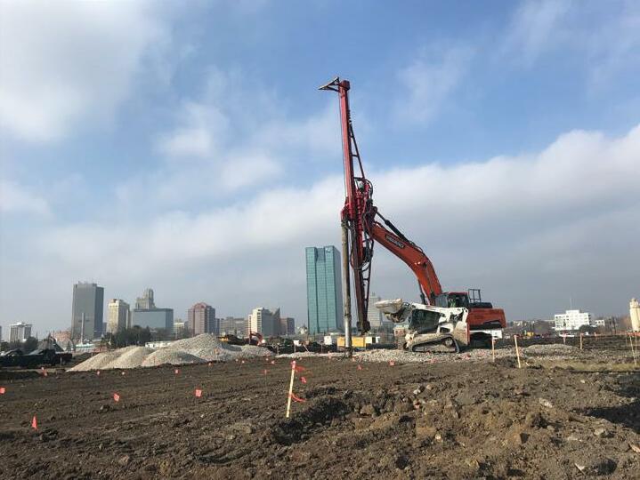


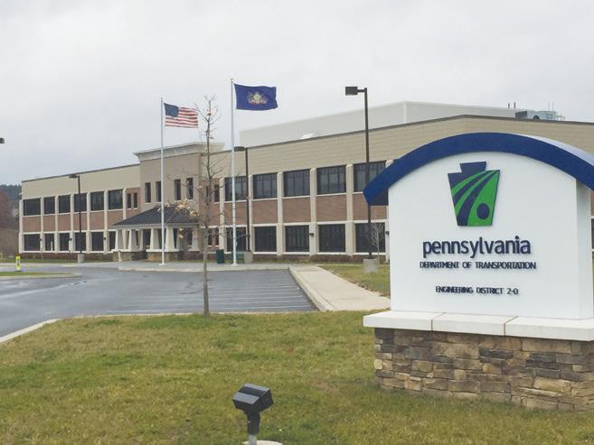

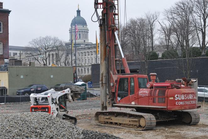


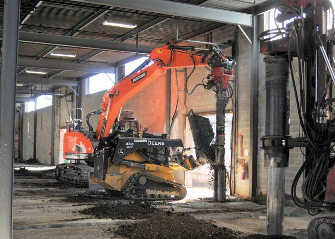


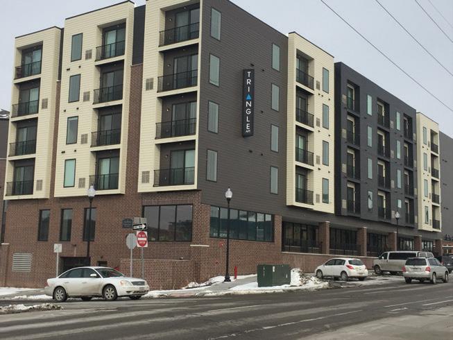
The National Council of Structural Engineers Associations (NCSEA) is pleased to publish the winners of the 2022 Structural Engineering Excellence Awards. The awards were announced Thursday, November 3 rd, during NCSEA’s Structural Engineering Summit, held at the Chicago Hilton. A video of the presentation can be found on the NCSEA website. The Awards are given annually; each year, the entries highlight work from the best and brightest in our profession. A new award was introduced this year at the Summit – The Structure of the Year Award. This new award was created to honor the most innovative and creative project, regardless of category or budget. This award was determined by an independent group of past presidents whereby they ranked the eight Outstanding Structure Category Winners based on the judging criteria used in each category. The award went to Climate Pledge Arena – Seattle, Washington; Thornton Tomasetti.
Awards were given in eight categories, with eight Outstanding projects awarded. The categories were:

• New Buildings under $30 Million
• New Buildings $30 Million to $80 Million
• New Buildings $80 Million to $200 Million
• New Buildings over $200 Million
• New Bridges and Transportation Structures
• Forensic | Renovation | Retrofit | Rehabilitation Structures under $20 Million
• Forensic | Renovation | Retrofit | Rehabilitation Structures over $20 Million
• Other Structures
The 2022 Awards Committee was chaired by Carrie Johnson (Wallace Design Collective, PC, Tulsa, OK). Ms. Johnson noted: “The judging was conducted in two rounds. NCSEA Past Presidents performed the first round; the second round was done by the Northeast Chapter of the Florida Structural Engineers Association (FSEA). The judges were truly impressed by the quality, innovation, and creativity of the award submissions.” The judges selected the winning projects based on the following criteria:

• the creativity of structural design


• the complexity of criteria or unique problems


• innovative application of new or existing material or techniques
• efficient use of materials and labor
• constructability challenges and solutions
Please join NCSEA and STRUCTURE magazine in congratulating all the winners. More in-depth articles on several of the 2022 winners will appear in the Spotlight section of the magazine over the 2023 editorial year. Visit the NCSEA website for more information at www.ncsea.com
e m.o.r.e. Cabin is a 900-square-foot private retreat on a hill overlooking Lac du Brochet, Québec. e building touches the site at only two points: a small concrete storage building supports the cabin at the top of the hill, and a steel mast supports the opposite end. e cabin cantilevers 25 feet beyond the mast. e structure consists primarily of glulam members and cross-laminated timber panels (CLT). Wood was chosen because of its sustainable qualities. Prefabricated glulam and CLT components reduced installation time, and the natural beauty of the wood panels eliminated the need for wall and ceiling finishes.
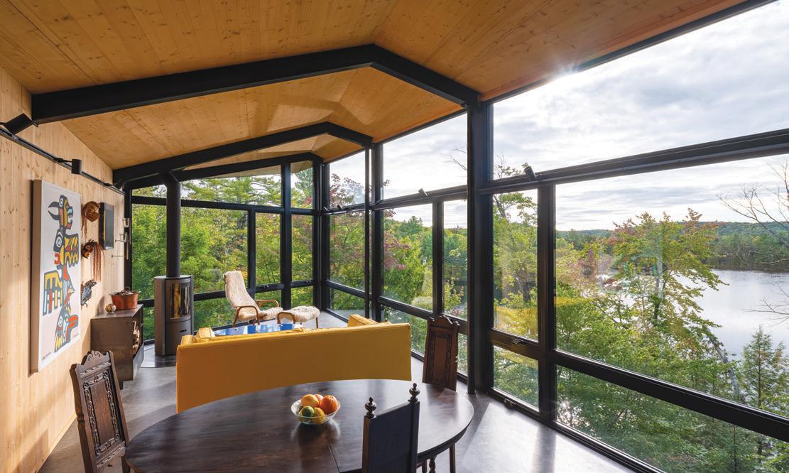
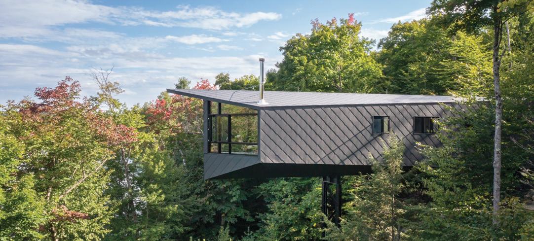

e Idaho Central Credit Union Arena models the use of timber in long-span sports facilities in North America. Inspired by the undulating landscape forms of the Palouse region, the 4,000-seat multi-use facility was designed as a dramatic gateway to the University of Idaho campus. e dominant feature of the structure is the majestic timber roof, a doubly curved plywood diaphragm supported by 150-foot hybrid timber/steel trusses, all carefully proportioned for both aesthetics and structural efficiency. A parametric model was created using genetic algorithms to perform structural optimization on the trusses.
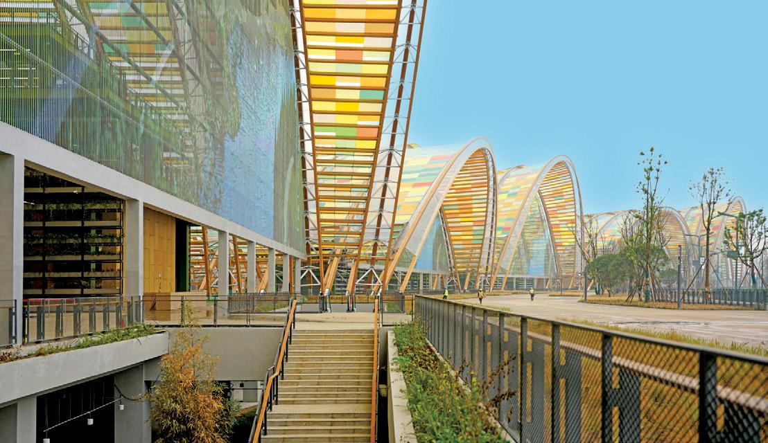
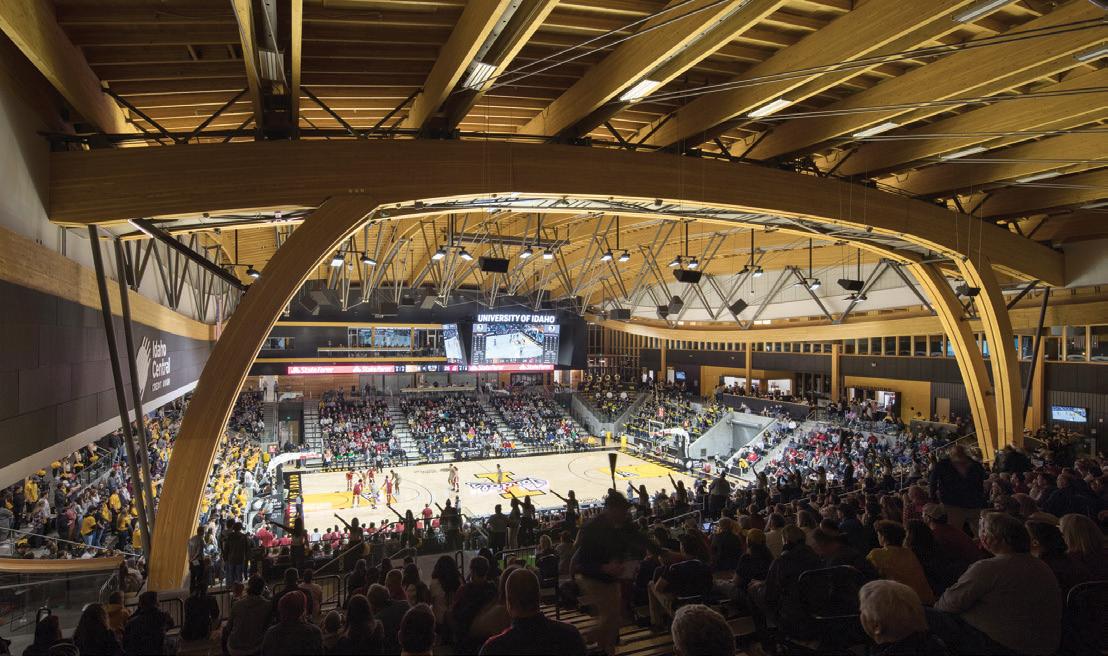
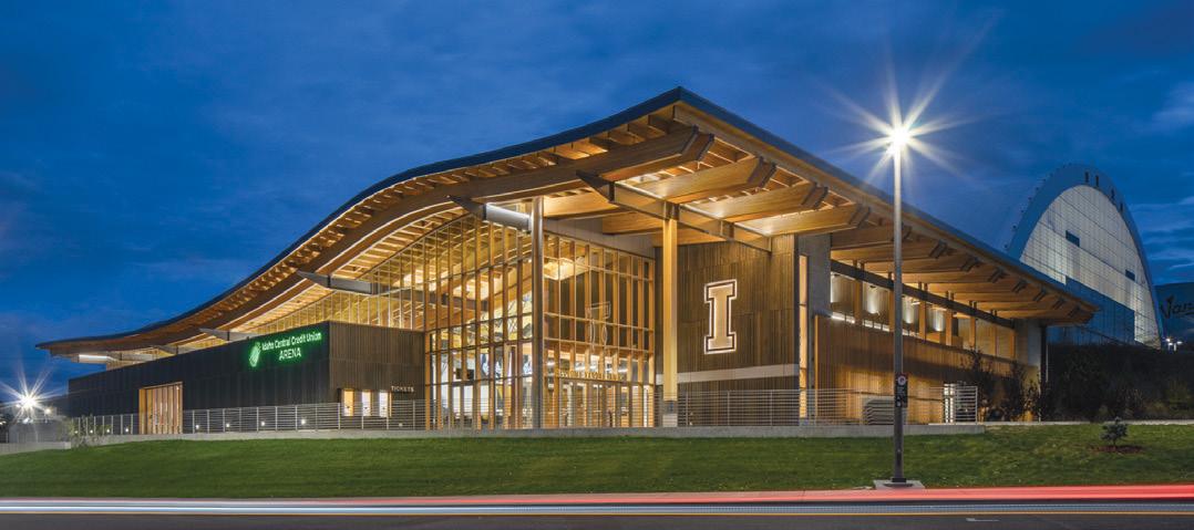
At over 807,000 square feet, the new Tianfu Agricultural Exposition is the largest timber structure in Asia and one of the largest in the world. is series of five vaults uses hybrid timber-steel Vierendeel-inspired trusses, achieving clear spans up to 360 feet and heights up to 144 feet. e unique wave of the building ensemble blends gently into the landscape, displaying agricultural products from the region and providing a direct connection with the surrounding farmland. rough the cooperation of team members on 3 continents, a series of world-class long-span timber structures was achieved.
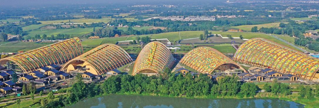
screen.
Spanning the Mississippi River between Iowa and Illinois, the $1.2B reconstruction of I-74 is an engineering marvel that will benefit the region for decades. e signature elements are a pair of basket-handle, true arch bridges with an 800-foot navigation span. e eastbound structure also supports a multi-use path, cantilevered outside of the rib, allowing pedestrians and bicyclists to cross the Mississippi River while taking in the wonderful views. Several ingenuities were implemented, including long, unbraced ribs with Vierendeel bracing, innovative stainless steel rods at the arch anchorage, and a hybrid foundation to transfer the massive thrust loads to bedrock.
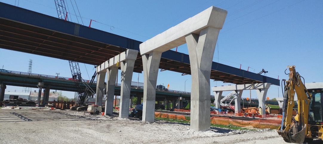
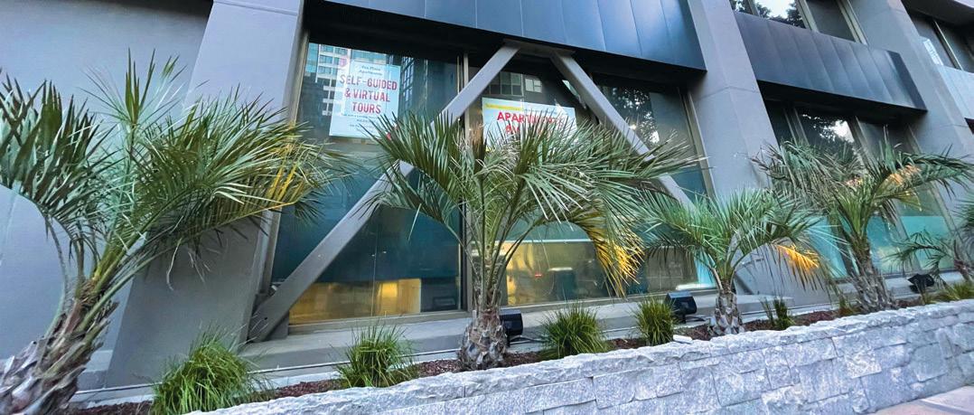
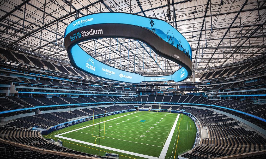
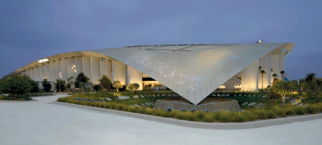
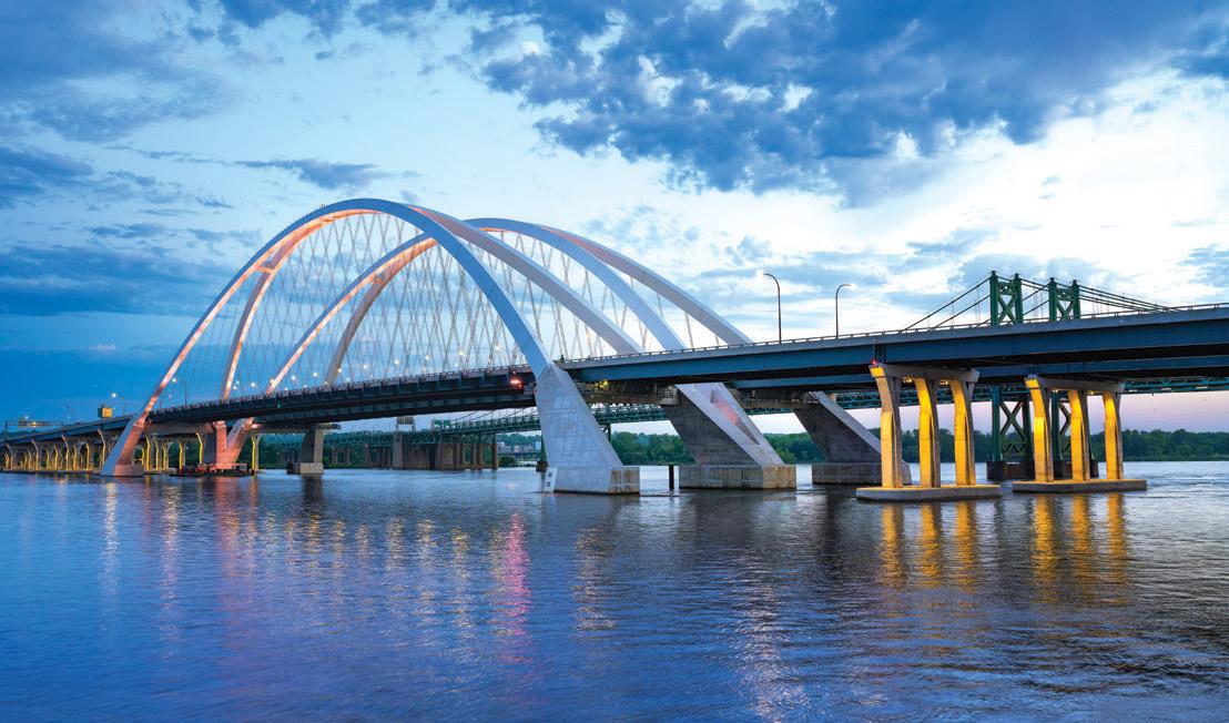
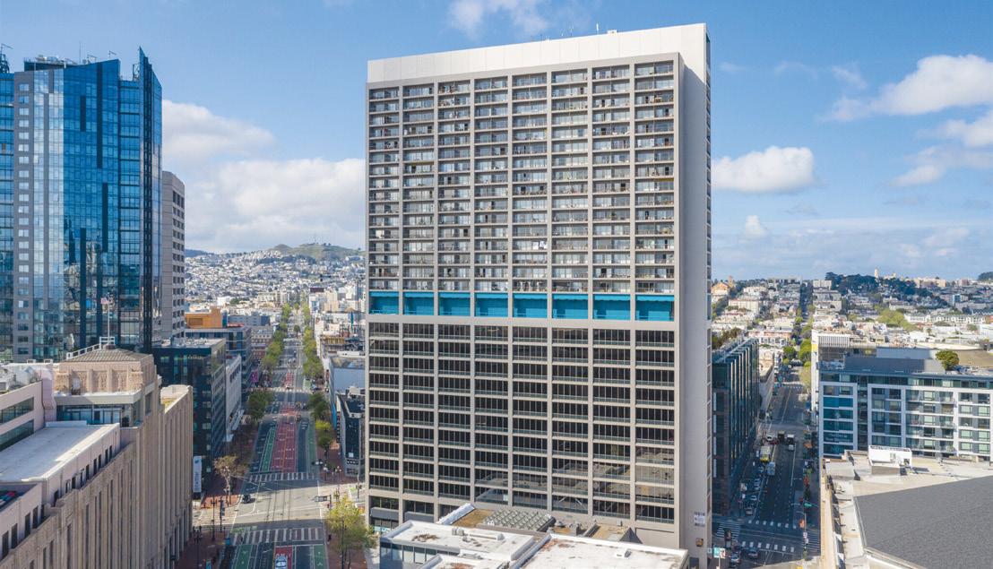
Tower is a 30-story steel building with an unconventional lateral system consisting of steel moment frames. ese frames have haunched beams
Pre-Northridge welded moment connections to both strong and weak axis of built-up columns in a space-frame configuration. e connections’ unique characteristics necessitated full-scale laboratory testing and extensive nonlinear response history analysis to assess the building’s seismic performance. e seismic retrofit scheme was specifically tailored to address concerns with excessive building drift and the potential for building collapse, including direct connection strengthening at the upper levels and exterior braced frames with fluid-viscous dampers at the lower levels.
SEATTLE, WA | THORNTON TOMASETTI Outstanding Project - Structure of the Year
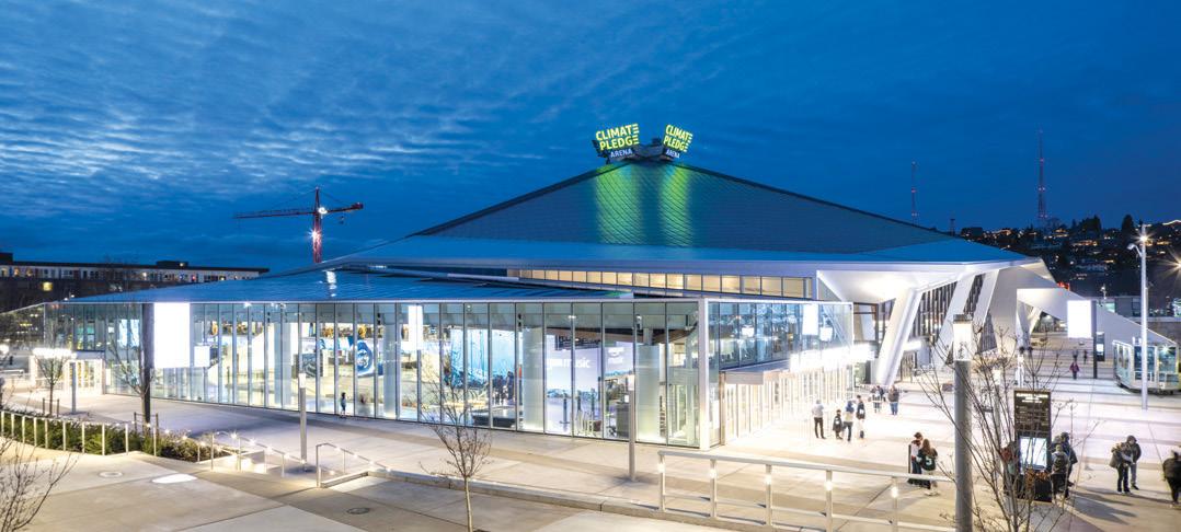
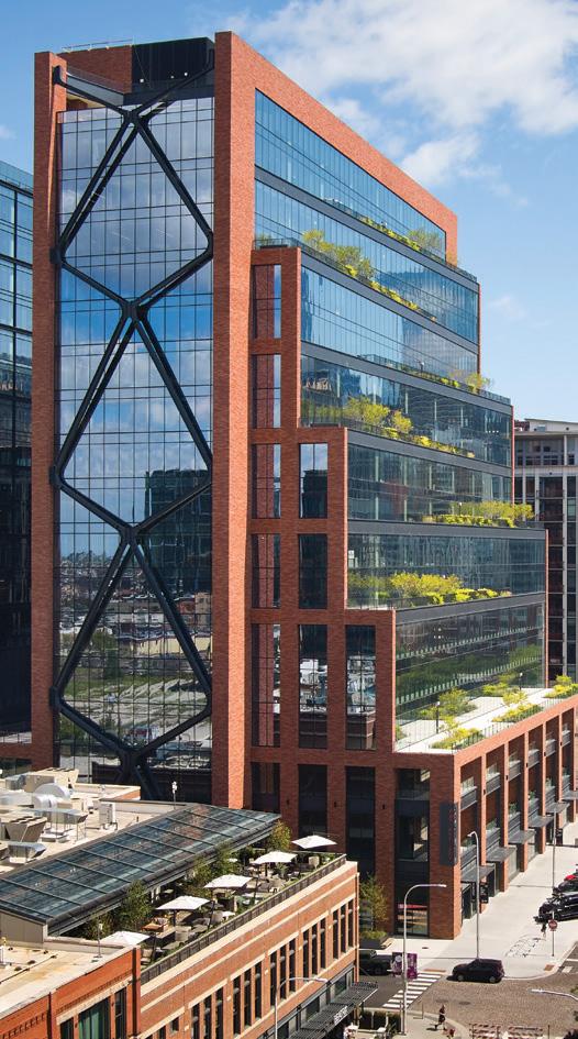
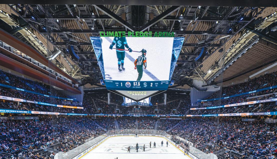

Seattle’s historic KeyArena has been transformed into a new home for the NHL’s Seattle Kraken. e $930-million renovation is now Climate Pledge Arena. To preserve the landmarked, 44-million-pound roof structure and exterior curtain wall, it was necessary to temporarily support the roof and build the new arena underneath. Additional challenges include high seismicity, an aggressive schedule, and a commitment to making it the first net-zero-certified arena in the world. e project team worked together to address these challenges and transform a historic venue into a first-class sports and event facility, which opened in time for the 2021-2022 NHL season.
Outstanding Project

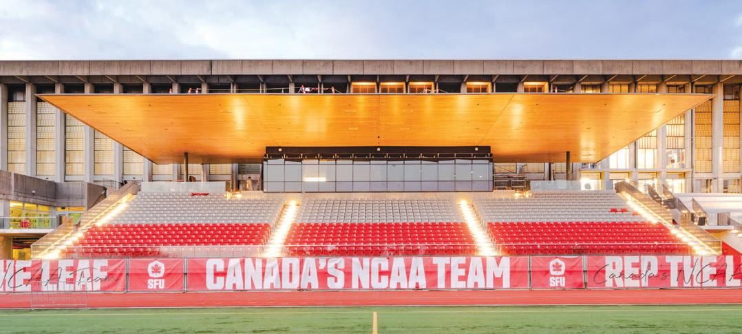
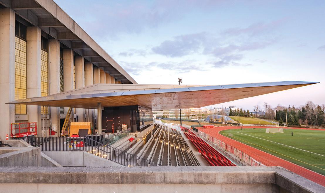
BURNABY, BC, CANADA | FAST + EPP


e new 1,800-seat stadium at Simon Fraser University is home to the SFU Athletics Team and a new facility for community and student events. e crowning piece of the design is a striking CLT canopy that cantilevers 52.5 feet, providing weather protection and unobstructed views for the spectators below. Early in the design process, the design team had the idea of hanging CLT panels below cantilever steel girders, providing a ‘wow’ statement of continuous wood structure. Supported by steel girders, the canopy required careful structural detailing to ensure the exposed structure was seamlessly coordinated with the design team’s vision.

Ben Nelson, P.E. – Martin/Martin


Marc Barter, P.E., S.E – Barter & Associates

Craig Barnes, P.E. – CBI Consulting


Mike Tylk, S.E. – TGRWA

Jim Malley, S.E., P.E. – Degenkolb

Tom Grogan Jr., P.E., S.E. – (Retired)


Vicki Arbitrio, P.E. – Gilsanz Murray Steficek
Barry Arnold, S.E. – ARW Engineers
Bill Bast, S.E. – Socotec
Carrie Johnson, P.E., S.E. – Wallace Design Collective
Jon Schmidt, P.E. – Burns & McDonnell
Ryan DuChanois, EI – Haskell
Doug Braaksma, P.E. – Automation Computer Concepts, Inc.
Abhijit Mulay, P.E. – Jacobs
Brendon Robas – Haskell
Haidyn Owens, EI – Haskell
Andrea Toro-Downard, EI – Haskell
Carrie Johnson, P.E., S.E. – Wallace Design Collective
Alex Fonteriz, P.E. – RS&H
Dan Charletta, P.E. – Structures International
Patrick Mull, P.E., S.E. – RS&H


Tom Grogan Jr., P.E., S.E. – (Retired)
Jeff Auld, P.E. – RS&H
Jeff McGee, P.E. – G.M. Hill Engineering, Inc.
Jay Patel, P.E. – Arup
Gopal Sudhirkumar, P.E. – Stellar
Ben Nelson, P.E. – Martin/Martin


Fast + Epp’s four-story home office building embraces design elegance and curiosity – traits the firm has become known for. e office serves as a living laboratory with new ideas and technologies being tested both during construction and throughout the life of the building. With an emphasis on promoting employee wellness and productivity, the building combines the latest in sustainable design strategies while taking full advantage of the spectacular mountain views to the north.


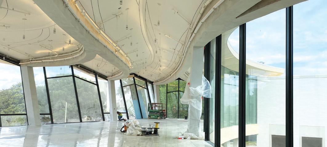


Designed for resiliency and sustainability, the Helios Education Campus includes a complex 2-story, 85,000-square-foot steel-framed building over a daylit 210-stall cast-in-place parking structure designed to adapt to future offices. e campus features offices and meeting spaces focused on postsecondary education advancement for the community. e structure evokes the geology of Arizona, including a canyon-like, landscaped amenity deck and a sculptural exterior façade. Feature stairs and concrete walkways appear to float.
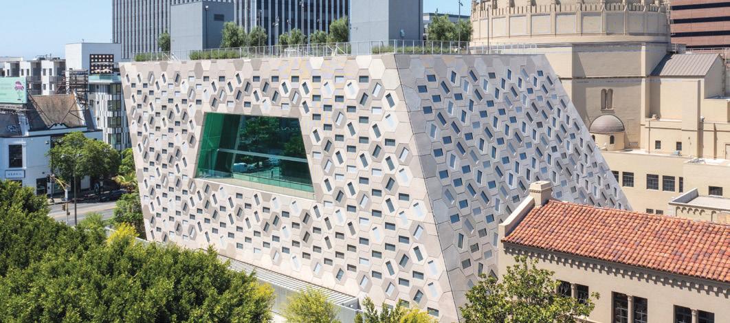

e reimagined Arkansas Museum of Fine Arts adds a concrete folded plate roof, dubbed the Blossom, to create a cohesive link between seven existing structures. For the analysis, the design team needed to accurately capture the folded plate behavior and establish a rebar layout early in the design process. e 8-inch mild reinforced slab achieved a thin and delicate profile. In addition, long spans and open spaces were achieved using the geometry of the folds.
the
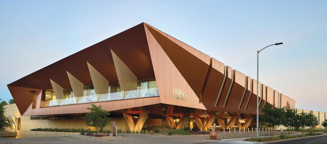
is a 3-story event and gathering place serving congregants and the community. Within a complicated sloped building geometry, the 57,000-square-foot building has multiple split floor levels, large open spaces, and assembly areas at each level, including the roof terraces. e design approach resulted in a cost-effective code-based structural framing system to accommodate the complex geometry, high seismic demands, and functional requirements.
campus in Los
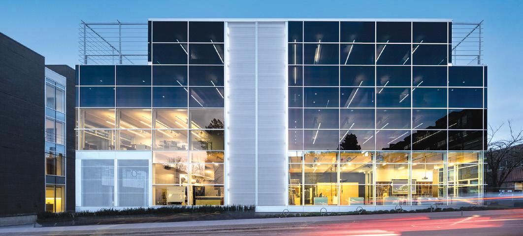
Carrie Johnson, P.E., S.E., Chair, 2022 Awards Committee
800 Fulton Market is a mixed-use office building marking the gateway to one of Chicago’s most dynamic neighborhoods. With setbacks and landscaped terraces, the 19-story design is proportioned to the Fulton Market District’s historic low-rise streetscape while connecting to the higher-density commercial district to the north. e building presents a bold structural expression, with external steel braced frames on the east and west facades, designed to resist wind loads while accommodating Chicago’s extreme temperature variations.
Wharf Parcel 8 is a 13-story mixed-use building. Situated over an active tunnel, surcharge on the tunnel and vibration/acoustics were important. Above grade, the hotel on the west side slopes outward at approximately 60 degrees. As the hotel continues to cantilever out, the residential east side also steps back at every floor, creating a wedding cake-type structure. Each floor plate geometry was different, and the center of mass for each floor continuously changed, creating internal stability challenges.
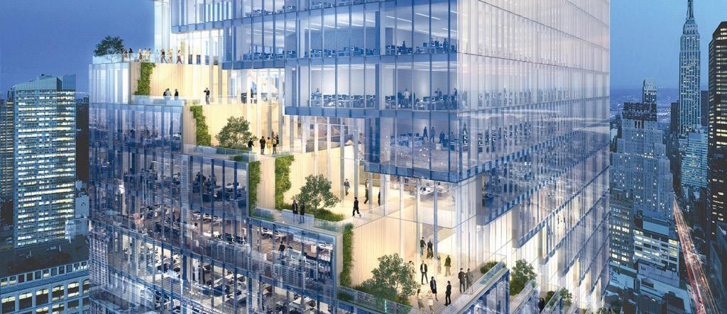


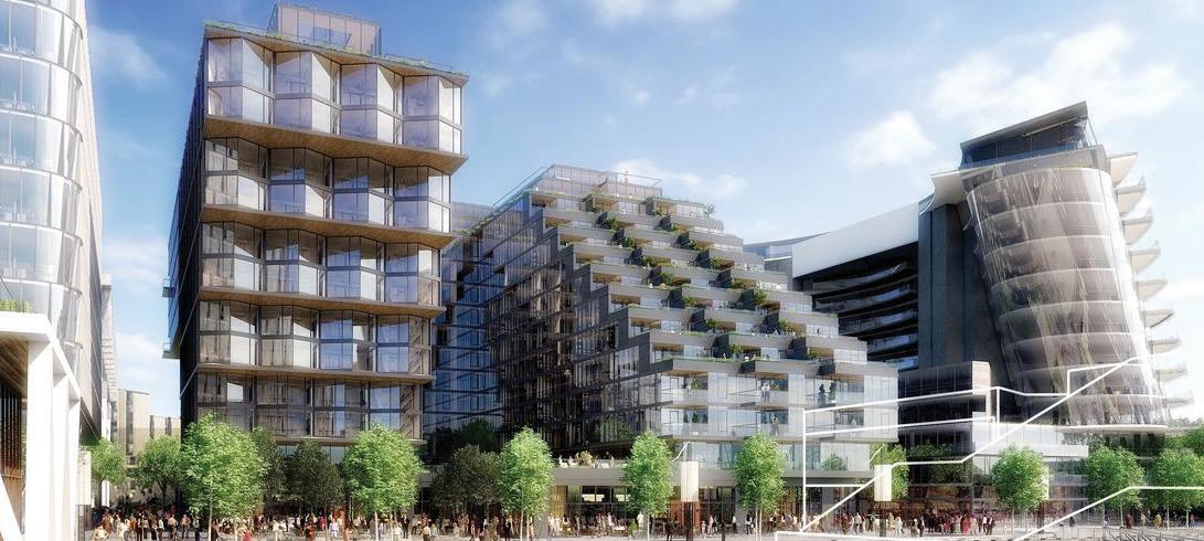

“ e Spiral” is a 66-story supertall commercial tower featuring signature terraces spiraling up the exterior resulting in unique floor plates for every level. e complex design included a repeating multi-story column-sloping system (inward and outward), resulting in horizontal forces in different directions on a floor. Horizontal floor trusses stabilize and transfer forces to the core. As the EOR, WSP performed 100% of the steel Tekla modeling in-house and the connection engineering in conjunction with CSD Engineers.
Microsoft’s commitment to fostering a deeply sustainable community resulted in North America’s largest mass timber building. e innovative structural design overcame a lack of code provisions – setting a precedent for more mass timber construction in the broader United States. e upgraded Silicon Valley Campus hosts 2,000 employees with new fitness, wellness, and technology centers, a theater, cafes, a parking garage, and an extensive living roof. Holmes provided structural alongside fire engineering to deliver this mass timber milestone.
e I-579 Urban Open Space Cap project created a unique 3-acre park spanning the interstate between Pittsburgh’s Lower Hill neighborhood and the downtown business and cultural center. e park remedies historical development that harmed the predominantly African American neighborhood. It integrates green infrastructure, elements by Hill artists, Hill District history story walls, performance and green spaces, an outdoor classroom, and so much more. “Frankie Pace Park” honors a Hill District civic leader and longtime champion of the poor.
400 California, a San Francisco Designated Landmark constructed in 1908, was evaluated and seismically retrofi tted using nonlinear response history procedures following ASCE 41-17. To improve seismic performance with minimum impact on the exterior and interior historic features, the roof level of the building was connected to the structurally separated but functionally connected adjacent 21-story tower using rotational friction dampers. is project is the fi rst application of the Damptech rotational friction damper device in the U.S.
520 South El Camino Real has been radically transformed into a modern, resilient workplace. is retrofit demonstrates that detailed seismic simulations coupled with an innovative design approach can result in unconventional solutions that create extraordinary value. e structural improvements addressed critical seismic concerns and reinvented, modernized, and extended the life of the building, all while controlling cost. Moreover, the engineering approach and strategies are replicable for similar seismically-vulnerable non-ductile concrete buildings.
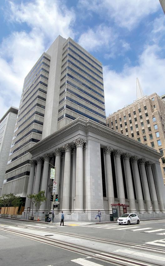
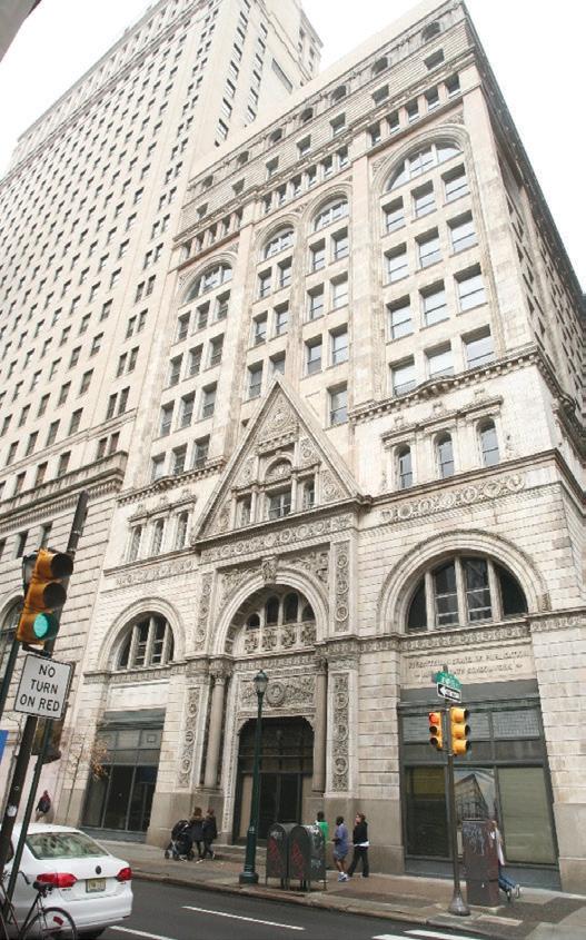
The 11-story Witherspoon Building is on the National and Philadelphia Registers of Historic Places and is considered to be Philadelphia’s first “skyscraper.” Constructed with Carnegie Steel beams between 1895 and 1897 for use by Presbyterian Church groups, this adaptive reuse project primarily included converting an office building to residential units. Several interesting and unique aspects presented many engineering challenges. Two especially unique aspects included the fourth-floor transfer and roof trusses and the built-up “Gray” columns.

Jamison Properties enlisted a project team to breathe new life into the existing structure at 3540 Wilshire – a thirteen-story, 1950s office building. e project seismically upgraded the building and preserved its steel-framed structure, bringing 206 live/work apartments to the upper floors and retail space to ground level while maintaining the original building’s mid-century character. e project also added 5 stories above its non-ductile concrete parking garage, retrofitted during the project, creating 123 additional units.
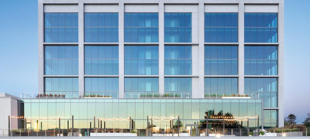
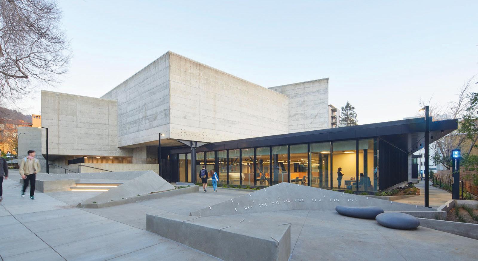
Bakar BioEnginuity Hub transforms a historically-significant former art museum from a structurally-deficient inoperable space into a coworking life science lab. e design, including a glass-fronted addition, modernizes the highly irregular 1971 building while honoring its original brutalist design. e team converted the upper-level galleries into glass-fronted labs that overlook dramatic cantilevered ramps hanging in a sky-lit double-height space. e project included a full seismic retrofit using buckling restrained braces located several hundred feet from the active Hayward Fault.
To expand Port Canaveral’s Cruise Terminal 3 (CT-3) in Florida, the project’s engineers needed something akin to a miracle – a cost-effective way to create structurally secure land where there was only ocean. To solve the technical constraints of the rebuild, the engineers turned to a lightweight geotechnical fill made from a rotary kiln-produced expanded shale, clay, and slate (ESCS). e unique physical properties of ESCS lightweight aggregate reduced applied
vertical stresses and lessened the lateral force acting on the steel bulkhead wall system. In addition, the decreased loading on the structure allowed the design team to reduce the gauge and diameter required for the supporting pipe piles in the steel bulkhead wall system. However, before realizing the benefits of lightweight aggregates, the design team first evaluated the cost; the manufacturing process makes lightweight aggregate more expensive to produce than natural quarried fill material. Despite the 155-million-dollar project budget, those overseeing the expansion needed to know how each material choice affected the project’s overall cost. So why did the engineers use a material that was so much more expensive out of the gate than other options?
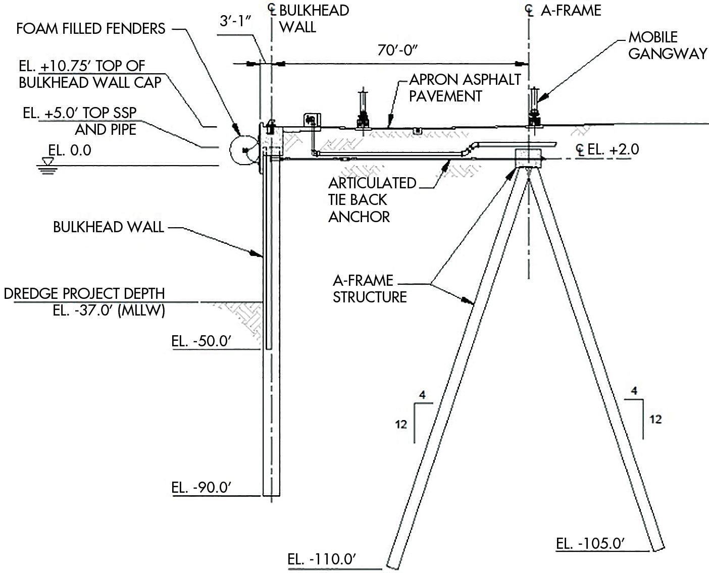
While lightweight aggregate costs more to produce, it provided other savings in the wharf structure that helped the CT-3 project stay within budget, reducing shipping costs, compaction efforts, and the support systems’ construction costs. Lightweight aggregate contributed to both material and labor savings due to its inherent low density and high internal friction angle.

Before diving into how lightweight aggregate helped engineers achieve the performance needs of the project while keeping construction costs within budget, it is important to outline the specifics of the expansion.
Since the 1950s, Port Canaveral has played a vital role in Florida’s trade and tourism industries. Sitting at the intersection of North-South and East-West
roadway corridors, the port was founded to facilitate commercial fishing and cargo trade before being expanded in the 1980s to also host cruise ships.
In 2018, as a part of the port’s 30-year strategic master planning process, the growth of the port’s cruise business was outpacing the infrastructure capacity. As a result, the port demolished the out dated and underutilized CT-3 to construct a new cruise terminal complex to continue serving its community. The construction plans included a 188,000-square-foot terminal structure, a new parking garage, and an expanded berth to accommodate the world’s larg est cruise ships, including the recently launched Carnival Cruise Line’s Mardi Gras, the largest cruise ship in the Carnival fleet to date. Because of CT-3’s location in the port, expanding the old berth to the requisite 1,309 linear feet required engineers to push into the ocean, creating land where there had been only water. This was destined to be the largest single construction project in the port’s 70-year history.
Using a value engineering approach, the engineers and port author ity recognized that lightweight aggregate would not only solve several technical aspects of the project but would also reduce adjacent system costs, allowing the project, when examined as a whole, to remain within budget.
Expanding CT-3 to the desired specifications required approximately 60,000 cubic yards of geotechnical fill and presented the first con struction hurdle. From shipping logistics to scheduling site delivery, the sheer quantity of material needed could cause longer construc tion durations and labor wastes as crews would have to partially stop construction to store the material and then carry it from its staging area to the terminal itself. The aggregate was shipped by rail to Florida, where it was unloaded onto trucks 15 miles from the project site. The lightweight aggregates’ comparatively low density reduced both the shipping costs and the number of railcar-to-truck transfers and truckloads delivered to the project site, making delivery logistics easier.
Whereas traditional quarried materials have a typi cal dry loose bulk density of 95 to 135 pounds per cubic foot, lightweight aggregates typically weigh between 35 to 55 pounds per cubic foot. This significantly reduced the number of railcars and trucks needed to carry the material from the manufacturer to the site. For example, depending on the material, a standard 20-ton dump truck can carry between 10 to 16 cubic yards of traditional geotechnical fill. As a result, delivering the required materials from the unloading site to CT-3’s construction staging area would take approximately 4,000 truckloads. By comparison, that same dump truck can carry up to 32 cubic yards of lightweight aggregate, reducing the required truck loads by 50 to 68 percent. A similar benefit is realized with the railcars.
Lightweight aggregate reduced the direct cost of shipping the fill material. It also streamlined the process, minimizing costs associated with coordinat ing shipping logistics, material handling, and onsite delivery. The reduced shipments also helped ensure that this part of the project would not be delayed. This way, lightweight aggregate started recovering its initial cost before it arrived on site.
When the material arrived, it continued to provide cost-saving ben efits. Placing lightweight aggregate requires no specialized equipment. Instead, contractors can use the same earthwork equipment, such as standard loaders, rollers, and plate compactors, to work with the material as they would with traditional quarried geotechnical fills. Due to the angularity and gradation of ESCS lightweight aggregates, the compaction effort required to achieve a suitable density is typi cally less. The objective of compaction of lightweight aggregate fills is to reach an optimal ratio of high stability and density. Accordingly, the material needs fewer passes from compaction equipment, which increases productivity. Over time, these savings can compound by reducing potential maintenance costs that could arise if natural aggre gate were used for fill. In addition, the lower applied vertical pressures from lightweight fill also reduce potential settlement over time, leading to lower maintenance costs for the new wharf.
In addition to reducing shipping, placing, and compaction costs, lightweight aggregate helped the CT-3 expansion project team reduce the gauge and diameter of the steel pipe piles in the bulkhead wall system. Lightweight aggregate made from expanded shale, clay, and slate contains air pockets throughout, creating a low-density and porous material. The manufacturing process produces a very angular material, contributing to a high internal friction angle and reduced lateral force on the support system.
Lightweight aggregate’s low-density and high internal friction angle, which can exceed 45 degrees, significantly reduces lateral earth pressure and fill dead loads compared to natural quarried fill materials, which typically have an internal friction angle between 30 and 38 degrees. Leveraging this benefit from the lightweight aggregate fill, the CT-3 design team was able to reduce the diameter and gauge of the pipe piles used for the wharf combi-wall and the A-frame tie-back anchor system providing considerable cost savings to the owner.
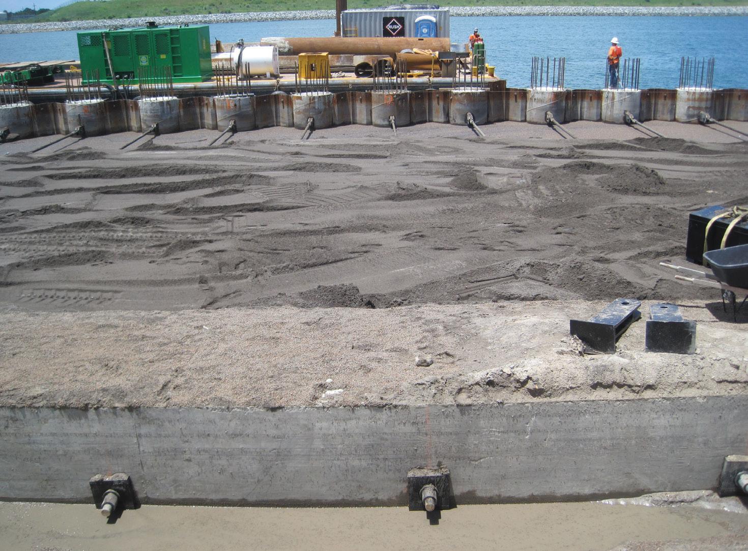


CT-3 was completed in mid-2020 and can now accommodate today’s massive cruise ships. As travel restrictions from COVID19 lift, the terminal is seeing the fruits of a value engineering approach. With almost a year and a half of successful cruise sailings from Port Canaveral, including several by the cruise ship Mardi Gras, the expanded CT-3 is quickly cementing Canaveral’s status as the second busiest cruise port in the world –with thousands of cruise passengers passing through every month.
ESCS lightweight aggregate’s low density and high internal friction angle helped engineers reduce the costs of the structural marine components of the terminal expansion. Furthermore, the ESCS manufacturing process produces a vitrified and durable product that will not degrade, contributing to the longevity of the new cruise terminal for Port Canaveral. The benefits realized from using lightweight aggregate on this project can also be translated to other projects. For example, whether or not a project needs to create land where there is only water, lightweight aggregate can help engineers and contractors reduce the costs of lateral support structural systems.■


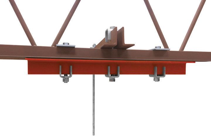

Jack Moore is the Southern Region Marketing and Technical Manager for Arcosa Lightweight. Jack has extensive experience in construction-product and geosynthetic sales with a geotechnical engineering market focus and is active in ASTM, TRB, ASCE, and the Expanded Shale, Clay, and Slate Institute (ESCSI).


At the corner of Seventh Avenue and 33rd Street, the East End Gateway provides a new direct connection from the street to Penn Station. is 40-foot-tall steel and glass canopy brings natural light to the Long Island Rail Road concourses below for the first time since the 1960s. Passengers arriving in New York City through the gateway are welcomed by the Empire State Building aligned directly in view. An innovative design and efficient construction allowed this monumental entrance to take on a life of its own above the busiest train station in the Western Hemisphere.
By the 2010s, Penn Station served more than 700,000 passengers per day as a hub for the Metropolitan Transportation Authority’s Long Island Rail Road and New York City Transit’s subway lines, New Jersey Transit, and Amtrak. For decades, the underground concourses that comprise
the station have been a cramped and dimly lit labyrinth. In 2019, the Metropolitan Transportation Authority Construction and Development Company (MTA C&D) embarked on a project to relieve crowding and improve circulation for the concourses. e East End Gateway Canopy, designed and engineered by Skidmore, Owings & Merrill in collaboration with AECOM, Skanska, and seele, serves to achieve these goals and transform the travel experience.
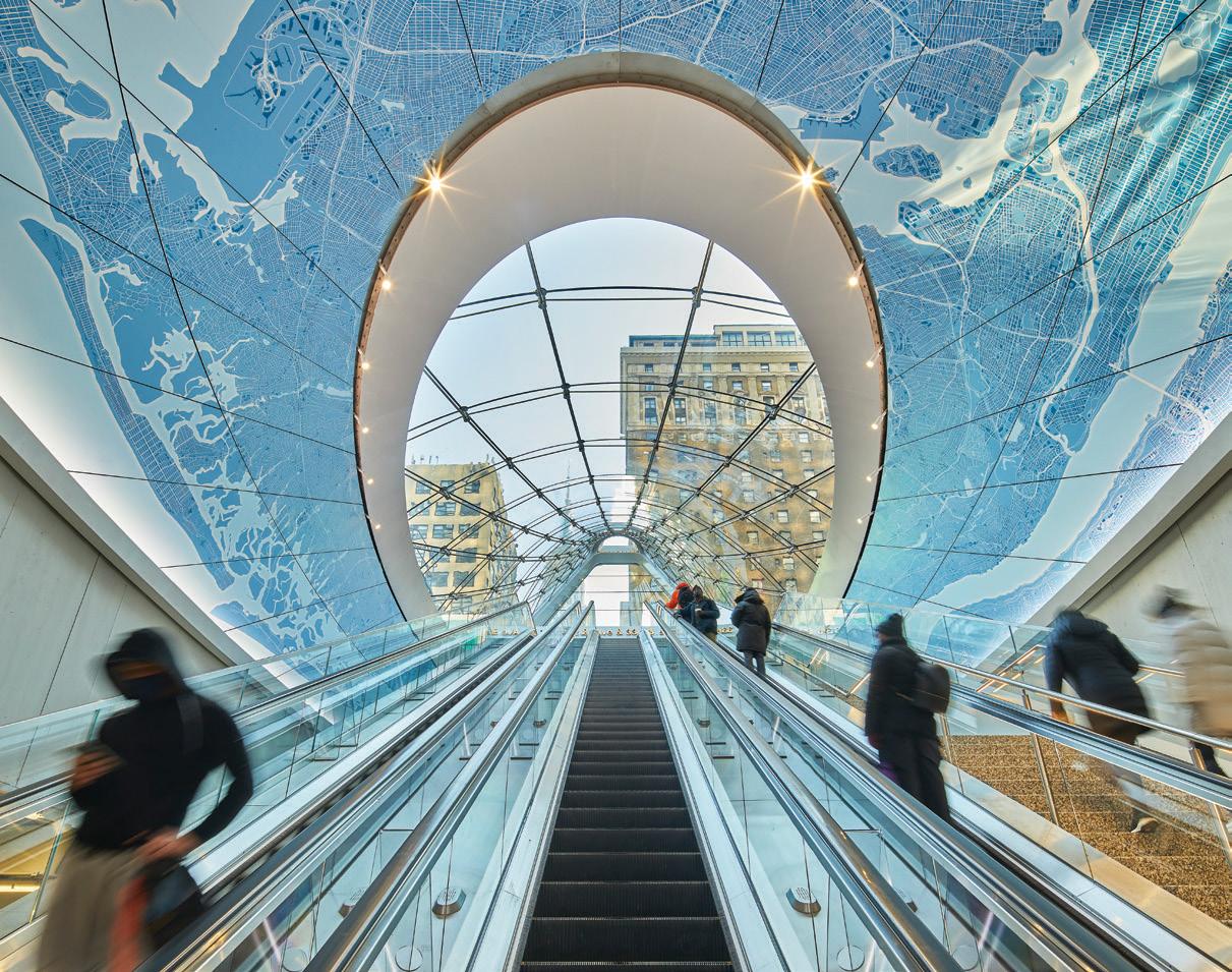
The east end gateway allows direct access to the concourse and brings natural light into the space for the first time.
e steel frame is inclined prominently at 50° to ensure maximum visibility from Seventh Avenue, while the glass enclosure curves gently down to the ground plane of the surrounding plaza. e glass appears as a luminous beacon with dynamic LED lighting at night. e new entrance nearly doubles the vertical circulation capacity of this overcrowded segment of the station, and more intuitive wayfinding helps ease congestion.
Two concepts guided the design of the canopy: daylight and directional ity. The canopy frame traces a partial ellipse at its base, which rises to the east towards a cantilevered crown. Double-curved glass encloses the western façade, while an inclined planar glass encloses the eastern façade. The glass enclosure maximizes transparency to bring daylight to the concourse below. The doubly-curved surface continues from the façade to the interior spandrel, naturally drawing passengers up to the street.
The curved west façade is supported on cables spanning in two direc tions between the steel frame. A cable net was chosen to support the curved glass façade to have the minimum structure and hence bring in the most light, compared to rigid elements that would cast larger shadows. The cables form a doubly-curved, anticlastic geometry, which provides structural benefits compared to a singly curved conic form. Concave latitudinal cables resist downward wind and gravity loading; convex longitudinal cables work to resist the uplift force of the wind as well as potential unbalanced loading conditions. This opposing curvature is inherently very stable, requiring less material and producing the façade’s iconic “swoop.”
The structure’s geometry significantly impacts the forces in the cables. The architecture and engineering teams collaborated on parametric models to define the geometry of the canopy and cable net. The design team devised a four-step parametric process for defining the form and validating the design; dynamic relaxation was used to generate the anticlastic geometry starting from an initial conic form. This geometry was then brought into a nonlinear analysis program, and prestress was applied to the cables. Then structural loading was applied to validate the design of the cables and the frame. This process allowed for quick iterations through different form parameters while maintaining the best structural performance by reducing deflections and the required prestress values.
The Architecturally Exposed Structural Steel (AESS) frame smoothly curves along the perimeter to create a seamless surface inside and out. Individual doubly curved plates form the box section, providing sufficient stiffness for the cables. The cable fittings, structural splices, electrical conduits, and drain pipes are all tucked within the box beam for a clean appearance, with covered access holes for future mainte nance. Similarly, the crown fits many systems inside while leaving a void for the glass skylight. The crown element was milled from a single block of steel to achieve this balance of form and function. Glass lights, up to 8 feet square, compose the façade, pushing the state-of-art for glass manufacturing. Each lite is fully chemically tempered glass, and hot slumped into double curvature. Glass clamps located at every cable intersection capture the glass, mini mizing the diameter of the attachments as much as possible. Close
coordination between the structure, architecture, and enclosure teams was required to develop and detail this system. The design team expanded the same parametric model used for form-finding to inform the design of the curved glass and connector elements and maintain constructability criteria.
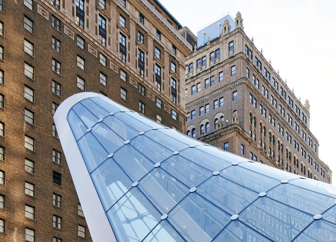
Innovations in design, detailing, and construction procedures stemmed from the complex support conditions and the challenges of serving one of the busiest train stations in the world.
The gateway punctures through a century-old existing structure that supports 33rd Street above the concourses and the tracks. The stiffness of the existing structure varies at different points around the canopy structure. In addition, the ongoing conversion of 33rd Street into a public plaza means that the expected loadings and deflections will vary in the future. The canopy is designed such that the tension of all cables is resolved within the frame itself, and the structure is independently stable sitting on its pedestals. The pedestals are positioned to provide a balanced center of gravity in all loading conditions, avoiding uplift in the pedestal connection. Slide bearings at the pedestals also help the cable net act independently and mitigate induced loads on the cables.
The geometry of the cable net allowed for efficiency in the construc tion sequence. The double curvature of the net means that tensioning the longitudinal cables also tensions the transverse ones proportionally. This allowed the transverse cables and one end of the longitudinal cables to be fixed on the frame while the entire system was pre-tensioned by
Implementation of parametric structural design workflow.
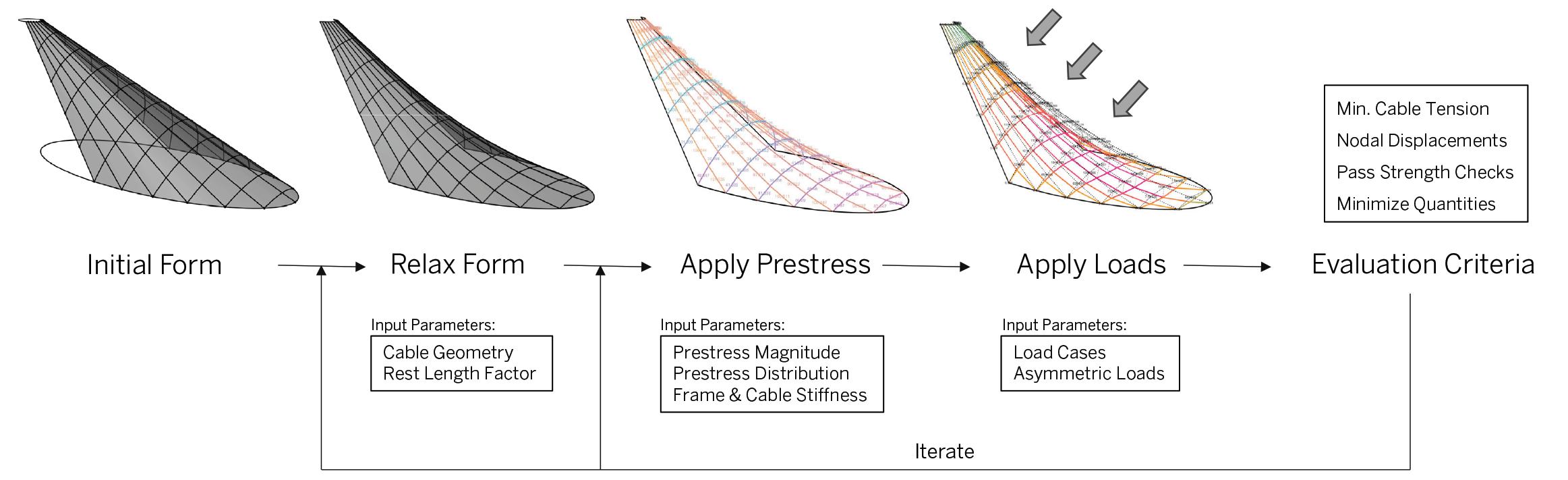
uniformly stressing the longitudinal cables. With proper calibration, this system successfully simplified the prestressing process. The self-contained nature of the structure also allowed for greater construction efficiency. After manufacturing, the standalone frame and cable net structure were fully pre-assembled and pre-tensioned at seele’s site in Pilsen, Czech Republic. Every cable has a wi-fi-enabled tension monitoring device built into the fitting, so cable tension and frame geometry adjustments were easily accomplished in the controlled setting. It was then disassembled, shipped, and reassembled on-site in New York, where the cable tensioning process could be repeated with a high degree of certainty. The construction process was also staged to allow passenger flow to continue unhindered in the concourse below. When completely assembled, each node landed within millimeters of its intended location, and all cable stresses were within 5% of their calculated values. The integrated cable tension monitoring system will continuously provide data for future maintenance operations. The cloud-based data stream reduces the need to manually access the concealed fittings to take readings.
The first step in an ongoing Penn Station improvement project, the East End Gateway opened to the public on December 31, 2020. The whole project took 20 months from design through fabrica tion and construction. The form of the canopy evokes movement and subtly hints at the dynamism of transportation. However, the shape is more than that; it is a story of the evolution of material efficiency. The collaborative parametric design process aligned struc tural performance with the architectural goals of the new landmark entrance. The canopy also plays a much larger role in its urban setting – as a gateway not only to Penn Station but to all of New York City.■
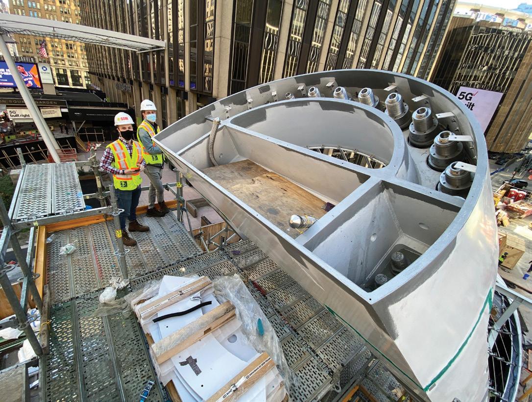
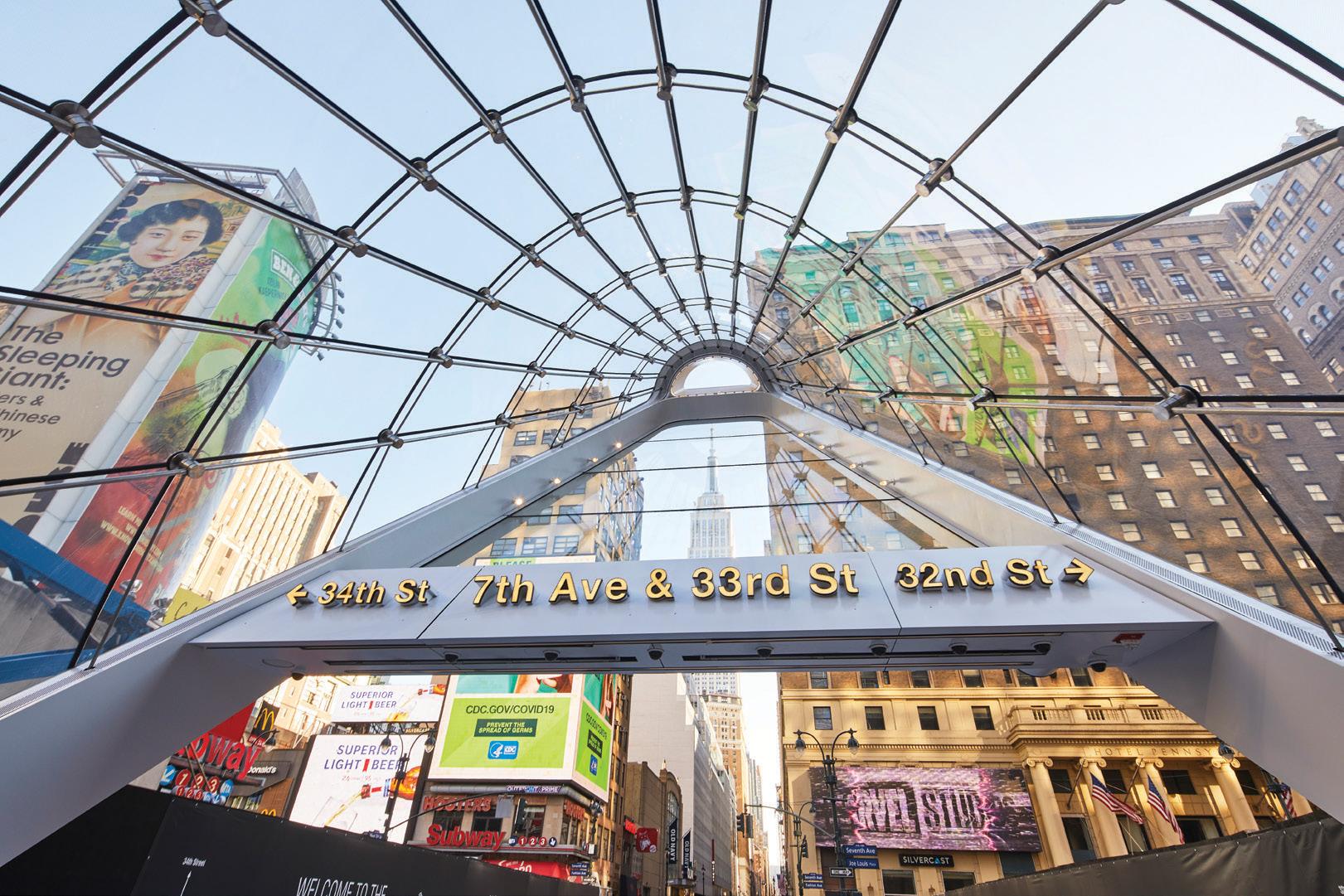
Alexander Jordan is an Associate at Skidmore, Owings & Merrill. Preetam Biswas is a Director of Structural Engineering at Skidmore, Owings & Merrill.
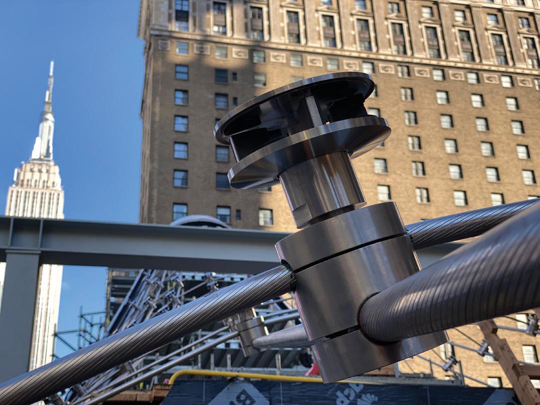
Owner/Developers: Metropolitan Transportation Authority Construction and Development Company; Long Island Rail Road; Penn District Station Developer LLC (Vornado Realty Trust)
Construction and Development: Long Island Rail Road; Penn District Station Developer LLC (Vornado Realty Trust).
Structural Engineer: Skidmore, Owings & Merrill in association with AECOM

Architect: Skidmore, Owings & Merrill
General Contractor: Skanska USA Civil NE
Canopy Fabricator and Installer: seele
The canopy frames the Empire State Building for passengers exiting the station.

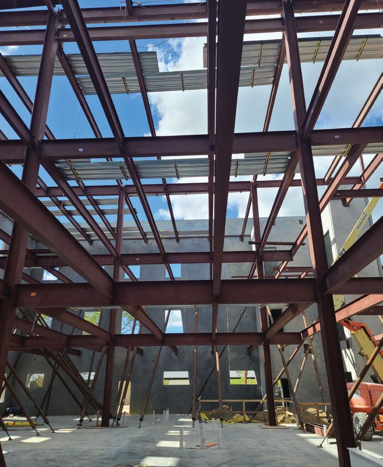

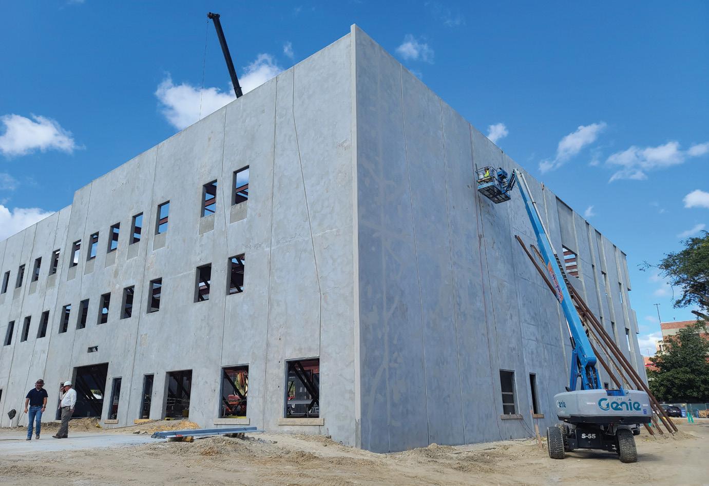
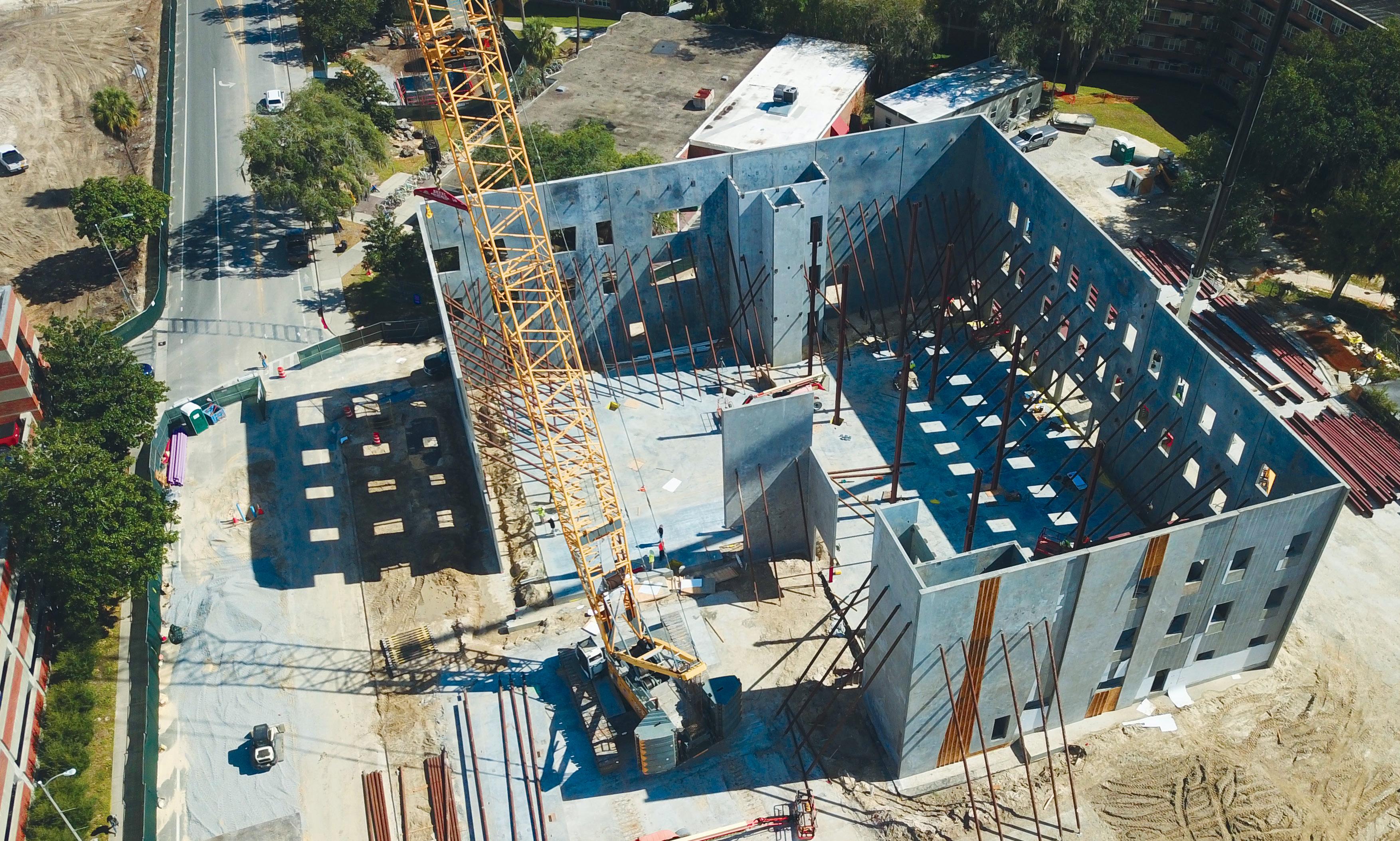 By Dylan Richard, P.E., and Stephen Blumenbaum, P.E.
part of an ongoing campus improvement program, the University of Florida and the University of Florida Police Department in Gainesville, Florida, recently commissioned their new Public Safety Building (PSB) located in the heart of the campus. e 50,792-square-foot three-story PSB consists of concrete tilt-up wall panels for the exterior and is supported by structural steel on the interior. e entire scope of the project also included a 6,931-square-foot renovation of the adjacent existing Centrex Building, which houses the University’s Emergency Management staff and emergency operations dispatch center.
e University of Florida contracted with Ajax Building Co. to provide pre-construction and construction services for the project, which consolidated five previous police department locations across campus under one roof. Ajax partnered with Walter P Moore, the engineer of record, on the PSB project to provide expedited bid documents and an advanced bill of materials for concrete and structural steel, as well as submittal and shop drawings for the subcontractors. is reformatted delivery process created schedule savings and improved coordination between trades.
According to BNG Construction, the concrete contractor, and Trinity Fabricators, the steel contractor, the shop drawings were ready soon after the contract was awarded – similar to a design-build job. Because Bluebeam Studio was also used on the PSB project, any updates to the drawings were registered in real-time.
The upfront costs on the PSB project were offset by competitive concrete and steel bids because the subcontractors were not required to include the in-house engineering costs. Ultimately, the savings were part of the final guaranteed maximum price and resulted in savings that were passed back to the university.
Walter P Moore designed each stage of the PSB’s construction documents using Autodesk’s Revit Building Information Modeling (BIM) software and Bluebeam Studio for architectural, structural, and MEP drawings. A Level of Development 400 (LOD400) BIM model was used for fabrication and assembly where the model ele ment is graphically represented within the model as a specific system, object, or assembly in terms of size, shape, location, quantity, and orientation with detailing, fabrication, assembly, and installation information.
A coordinated effort with key building team members resulted in developing a BIM execution plan. This plan was implemented during the PSB project’s design, pre-construction, and construction phases. A detailed analysis of the concrete and structural steel com ponents was performed regarding the project’s timeframe during pre-construction and construction. The comparative analysis was performed so Ajax could determine if there would be value to the project utilizing Walter P Moore’s reformatted delivery process. This analysis was essentially Ajax’s go/no-go evaluation. It compared the actual timeframe that Walter P Moore released deliverables before construction – including bid documents, preliminary reports, advance bill of materials, LOD400 model, and shop drawings – to what would have been the standard process of having subcontractors perform this work after a guaranteed maximum price was agreed upon with the university.
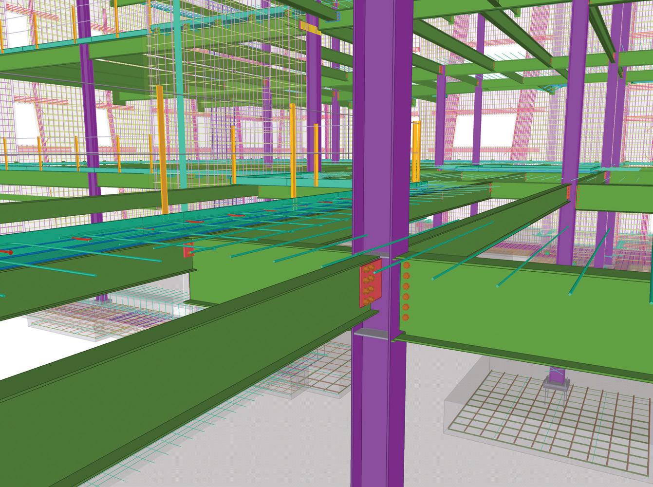
The actual timeline for the PSB project – which again benefited from this reformatted delivery process – revealed significant time savings compared to a typical project timeline. In the PSB timeline, the rebar was released for fabrication on June 7, 2021, and delivered to the site three weeks later. If a post-guaranteed maximum price timeline had been used, the rebar would not have arrived onsite until August 9, 2021 – a six-week improvement in rebar delivery. The structural steel comparison shows steel ready for delivery on July 9, 2021. In comparison, the post-guaranteed maximum price option was September 6, 2021 – an eight-week difference in expedited delivery. As a result, after considering other critical path items unre lated to structural scope, the PSB project shaved approximately one month off of construction, which was eventually carried through to the completion of the project. The significance was that the structure was completed a month sooner than it would have been had Walter P Moore’s reformatted delivery process not been used, allowing followup trades to begin their work sooner than originally scheduled. This month time savings also carried directly through to the completion of the project.
In addition to the PSB project, part of Walter P Moore’s overall scope of work included the renovation of the Centrex Building, which was initially constructed in 1967, expanded in 1973, and renovated in 1985. A BIM model was also developed for the existing building
based on construction documents from its various phases and site visits. For this project, the interior of the building was gutted and reconstructed. Additionally, two cast-in-place concrete columns were removed and replaced with new steel transfer beams supported by widened and strengthened cast-in-place concrete columns and foun dations. Walter P Moore also detailed the new steel and cast-in-place concrete reinforcement for the Centrex Building.
One unique component of the tilt wall design was the blend of archi tectural and structural design. The use of tilt walls on the PSB project was a solution that helped to get the overall project under budget, a savings released because the tilt walls function as both structural components and the building envelope.
Walter P Moore worked with SchenkelShultz Architecture to establish criteria that allowed architecture design to be infused into the exterior faces of the tilt wall panels instead of just flat concrete walls with punched openings. All tilt walls have a minimum constant structural thickness of 8 inches and are thickened up to 12.75 inches in various locations to create reveals and recesses in the panels. Because the panels were structural, Walter P Moore modeled every panel using Revit to create the design documents. Tekla was used for the LOD400 model to ensure all architectural reveals and recesses were included. This was beneficial when coordinating the architectural design. Furthermore, it was helpful to convey the structural and architectural design to the construction engineering team and improve the fidelity of the LOD400 model.
The PSB’s structural system utilized multiple trades that had to be carefully coordinated to ensure proper load transfer between sys tems. For example, the structure’s interior is a traditional steel frame, which was straightforward for the steel contractor, Trinity Fabricators. However, the steel connects to the tilt walls via embed plates that were specifically located and coordinated with the reinforcing in the tilt wall panels. Using an approach that brought multiple trades to LOD400 in a single model, Walter P Moore ensured that all inter related structural components were designed internally – none were delegated – and were coordinated at a fabrication level, so there were no conflicts between the trades.
The coordination control on the PSB project allowed for effective and more detailed communication from the project’s onset. The com munication between Walter P Moore, Ajax, BNG Construction, and Trinity Fabricators, even before the bidding, allowed pre-bid questions to be answered promptly. Furthermore, it allowed for sequence strate gies to be established and incorporated into the final bid documents. Post-bid coordination and communication efforts ensured that scope was awarded correctly and without delay, eliminating overlap and gray areas during construction. For example, Walter P Moore held meetings with the entire building team to share the LOD400 fabrication model to ensure there was no wasted material, which assisted in keeping the cost within budget. Plus, having all the trades coordinated saved on field fixes and mistakes that typically cause schedule delays and change orders. As a result, the project’s scope was clearly understood during the buyout and fabrication of the structural materials.
On a typical construction project, concrete contractors earmark 7-10 percent waste for rebar and 10 percent for concrete in their bids. On the PSB project, no waste factor for rebar was needed because an accurate bill of materials was issued. This savings equated to more than 6 tons of rebar and over $14,000 in cost savings – simply by advancing the rebar to the LOD400 level (which is above and beyond current industry practice) and making no other changes to the project.
Two cast-in-place concrete columns were removed and replaced with new steel transfer beams as part of the Centrex Building reconstruction.
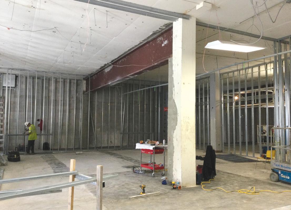
Additionally, structural steel bids do not typically factor in waste as steel sections are produced in standard lengths that are then cut to size based on the project requirements. While waste is minimized by using modeling software and CNC equipment, there are typically some minimal lengths of cut that would drop to the floor in either option and be recycled back into the steel-making process. Thus, the waste would essentially be the same regardless of who details the steel. As a result, there were no material savings to report regarding the structural steel.
Ultimately, the University of Florida approved the additional upfront funding for the collaboration between building team members during the pre-construction phase. These costs were offset and provided sub stantial savings post-bid and post-construction.
Coordination among the building team to expedite the concrete and structural steel documents during pre-construction and post-bid was a seamless experience. The process created a level playing field for the pre-qualified bidders, eliminated waste factors in the bids, and was helpful in awarding contracts. By expediting the submittal process, procurement allowed deliveries to be released and conveyed to the site ahead of traditional processes, so the master schedule was maintained.
In the current construction market and its volatility regarding the availability of materials and cost escalation, owners and other project stakeholders should consider creative alternatives to project delivery to mitigate these effects. This holds true regardless of project size, type, or complexity. The results on the PSB project demonstrate the improvements that are possible. In the end, effective com munication on the PSB project saved time and money across the board and allowed for success with minimal field issues.■
).
Owner: The University of Florida, Gainesville, FL
Structural Engineer: Walter P Moore, Houston, TX

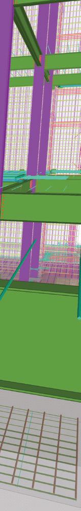
Detailer for Structural Steel and Reinforced Concrete: Walter P Moore, Houston, TX
Architect: SchenkelShultz Architecture, Orlando, FL
Contractor: Ajax Building Company, Midway, FL
Concrete Contractor: BNG Construction, Sanford, FL
).
Steel Contractor: Trinity Fabricators, Green Cove Springs, FL
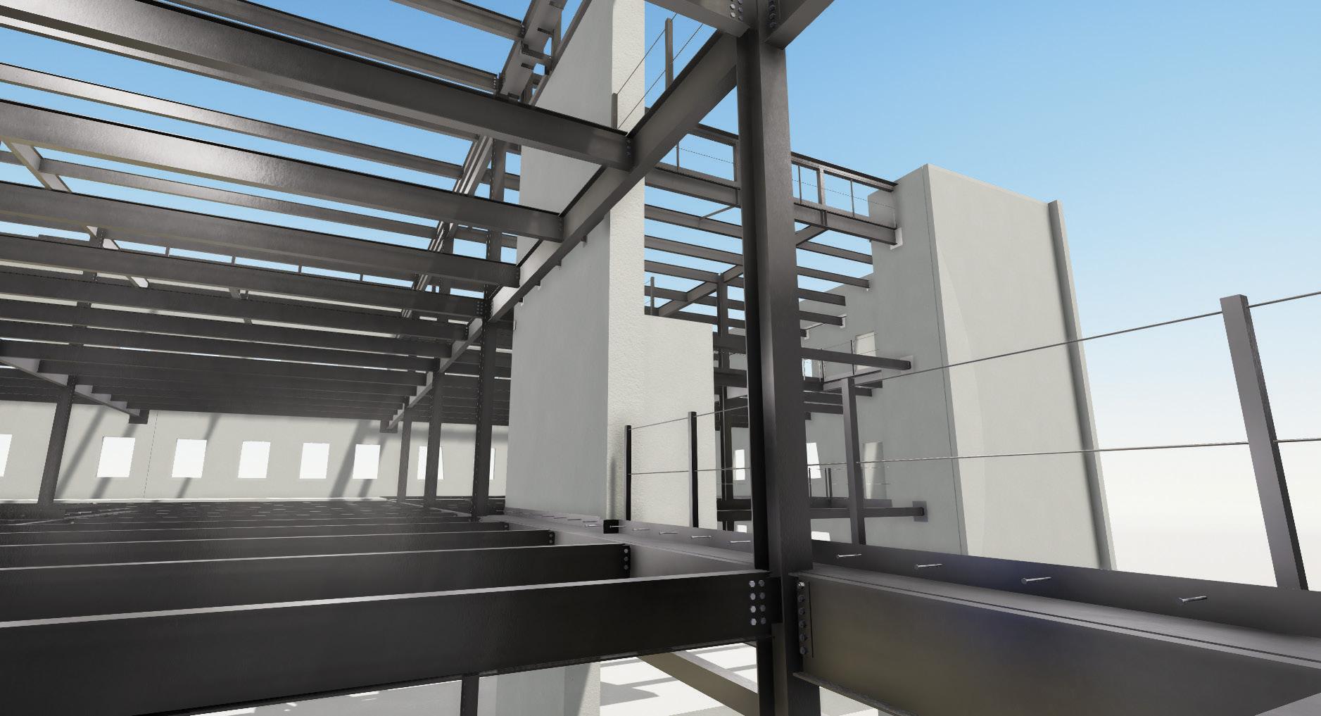
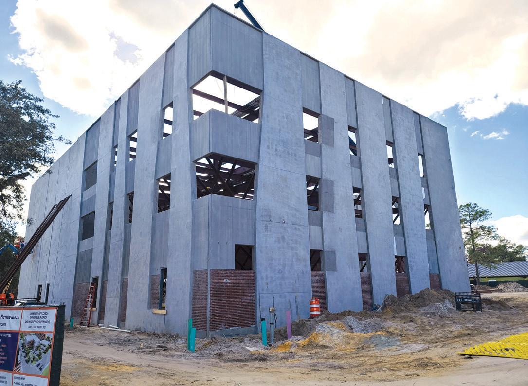

 BY PAUL EVANS, P.E., S.E.
The New York Public Library (NYPL) system has served New York City since 1895, providing, as noted on its website, “free books, information, ideas, and education for all New Yorkers.” While many people may picture the grand marble façade and imposing lions of the Stephen A. Schwarzman Building (SASB) at Bryant Park (famously featured in Ghostbusters, among other movies and pop culture), SASB has been solely a research library since 1970. In that
year, the circulating division of the branch, the part of the library that allows checking out books and materials, moved across the street to the upper floors of the Arnold Constable & Co. department store. is new branch was named the Mid-Manhattan Library.

Long room slab edge – long-span deck (right side) framing into beam upset into the slab to provide required head height clearances below the new mezzanine levels. Note that a cast-in-place concrete slab (left side) was utilized at select bridge locations.

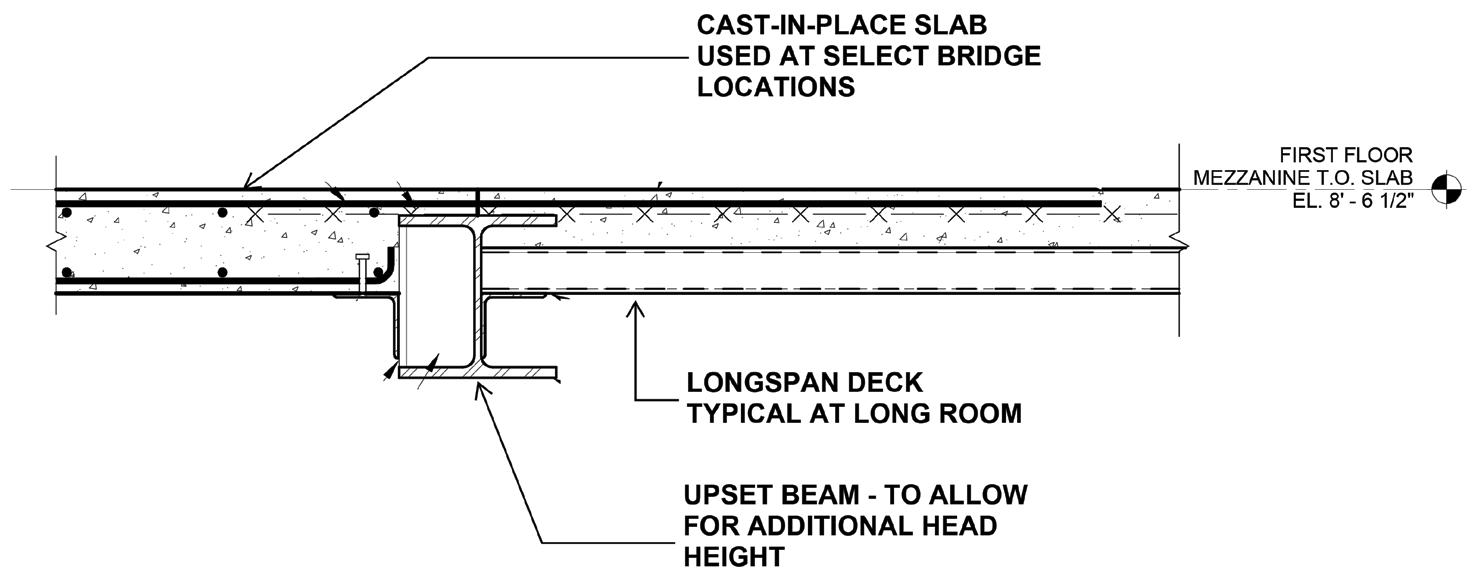
e Mid-Manhattan Library quickly became the busiest circulating library in the NYPL system and took over the entire Arnold Constable building in 1980, undergoing a complete building renovation in 1982. e building sat, aging and unchanged, for the next 30+ years until a new renovation was announced in 2016. e gut renovation of the 6-story steel-framed, cinder-slab building aimed to maintain the existing capacity for approximately 400,000 books while increasing space for occupants and community learning programs, adding new business, children, and teen libraries, and fully modernizing the MEP and IT systems. To achieve these goals, the architects, Mecanoo and BBB, proposed a new 3-story rooftop addition, the creation of the long room stacks by inserting new mezzanine levels between existing floor plates, and improved circulation throughout the building.
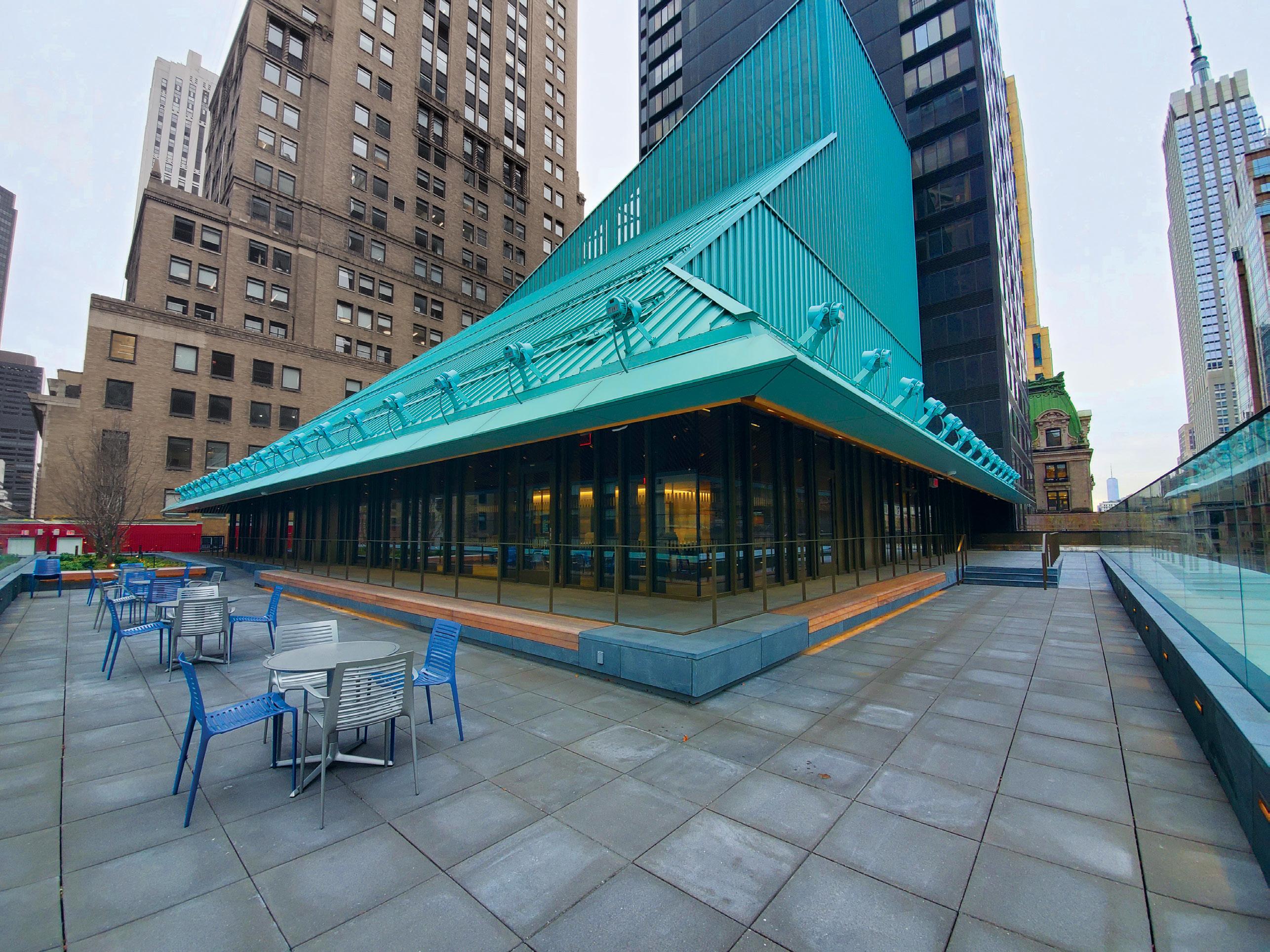
The existing structure was built in 1915 and was constructed of concrete and terracottaencased steel framing with draped mesh cinder slabs. Though there was no distinct lateral system, all beam-to-column connec tions had wind clips providing moderate frame action at all bays, as was typical of the time of construction. The building was founded on shallow foundations with mul tiple levels of steel grillage beams encased in concrete. Reviewing original building infor mation and evaluating existing column and footing sizes determined that the original structure was likely built with an intention to add multiple levels in the future. This overde sign allowed for the insertion of additional long room floors and a new 3-story addition without any existing column or foundation reinforcing.
In a creative use of space by the architects, the existing 3rd and 4th floor framing along the eastern-most end of the building was removed and replaced with 4 mezzanine levels to create the long room, a modern interpretation of the stacks found in older libraries. This move allowed for additional high-density book storage while creating an ample atrium space connecting levels 2, 3, and 4 and showing off a large portion of the library’s vast collection of books. However, to squeeze four floors where there had previously been two, the architects needed a thin, beam-free structure for the long room. The span of the long room varied from 19 feet to 22.5 feet and needed to support a library stack live load of 150 psf. In keeping with the theme, a long-span metal deck was chosen, specifically a 3.5-inch-deep acoustic deck with 4.5 inches of normal weight concrete topping for a total floor sandwich 8 inches deep. As the live loading and deck span pushed the deck to its limits, a full composite analysis of the deck was con ducted to verify the floor’s strength and serviceability performance. As a result, 6,000 psi concrete was required, and longitudinal rebar was added to achieve the longer span conditions and allow for required MEP openings in the deck. Shoring and sequencing the demolition in this area to install the new deck was also crucial, as floor removals tempo rarily unbraced existing double-height columns. The new long-span deck also required shoring until the concrete had set and was able to re-brace the columns. With the limited amount of space in the existing building, the only direction to go for more square footage was up! A 3-story rooftop addition was proposed to provide three large multipurpose spaces, a café, an outdoor public space, and a new space for major mechanical and elec trical equipment. Mecanoo developed a unique massing scheme for the addition with sloped roofs, large, column-free public spaces, and efficient but crowded back-of-house and mechanical spaces. The original roof structure outside the new addition’s footprint was reused to support a new public occupancy roof
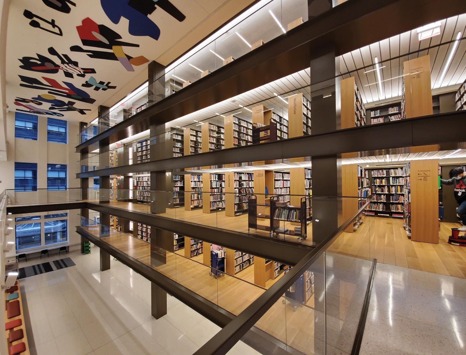
and roof garden – this required welded reinforcing of the original riveted connections at many of the roof girders. The rooftop addition required extending many existing columns, which were arranged in a classic rectilinear grid, approximately 4 feet higher, to create a new platform level. This platform level provided the first floor of the new addition and a landing point for the proposed irregular column grid required for the additional new roof levels above. An array of HSS tube columns along the edge of the platform, mimicking and hidden behind new window mullions in the multipurpose rooms, supported the base of the sloping roof that made up the Wizard’s Hat addition. In contrast, a main zig-zagging column line and a large full-story truss supported the top and sides of the slope and the two mechani cal levels of framing above. The lateral system of the addition, which per the New York City Building Code’s (NYCBC) unique approach to renovations was only required to be designed for wind loading, is a combination of braced frames at the south face of the addition and moment frames throughout the main occupiable areas.
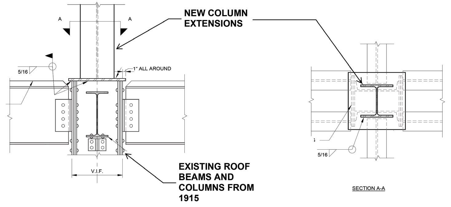
Edge of slab at new elevated platform level at the existing roof above original roof framing. Perimeter HSS tube column (hidden behind mullions) and occupiable roof terrace slab are also shown.
A name change came with the renovations, new addition, and new resources. Upon the building’s opening, the Mid-Manhattan Library, or MML to those who frequented it, became the Stavros Niarchos Foundation Library, or SNFL (“sniffle,” if you were wondering). The sad step-sibling of the more famous SASB main branch building, once referred to by one of its own as an “embarrassment” to the NYPL system, is now a modern, open, inviting, and unique building in its own right. It proudly boasts one of the few totally free public roofs in New York City, and the only one in midtown Manhattan, while continuing the long NYPL tradition of “free books, information, ideas, and education for all New Yorkers.”■
Long room under construction. Shoring in place (highlighted in red) as the long-span deck is installed and existing 4th-floor steel is demolished to create the new atrium.
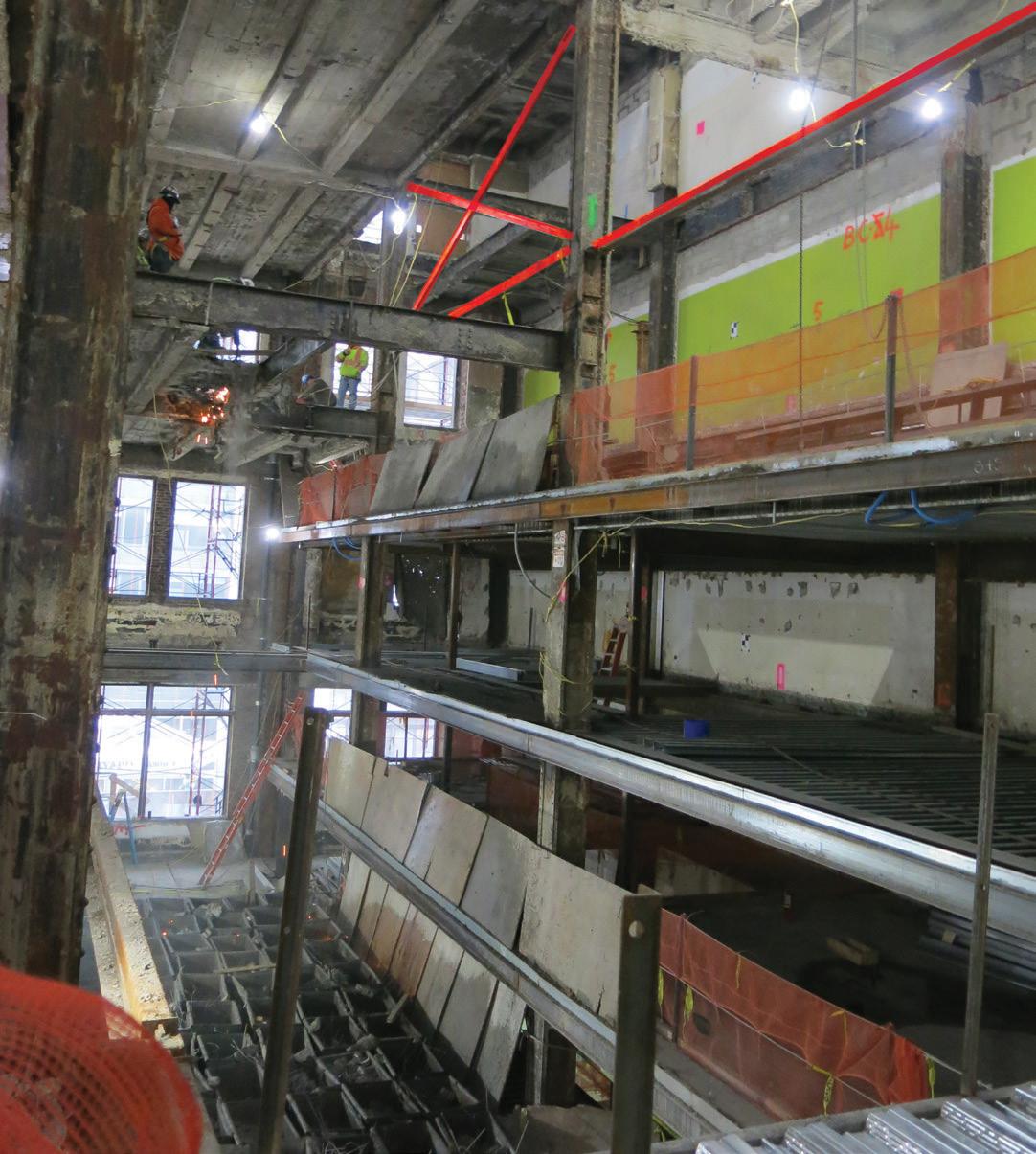
Paul Evans is a Structural Design Specialist at Turner Construction’s Engineering Group and Adjunct Professor in New York City (paevans@tcco.com).

Project Team
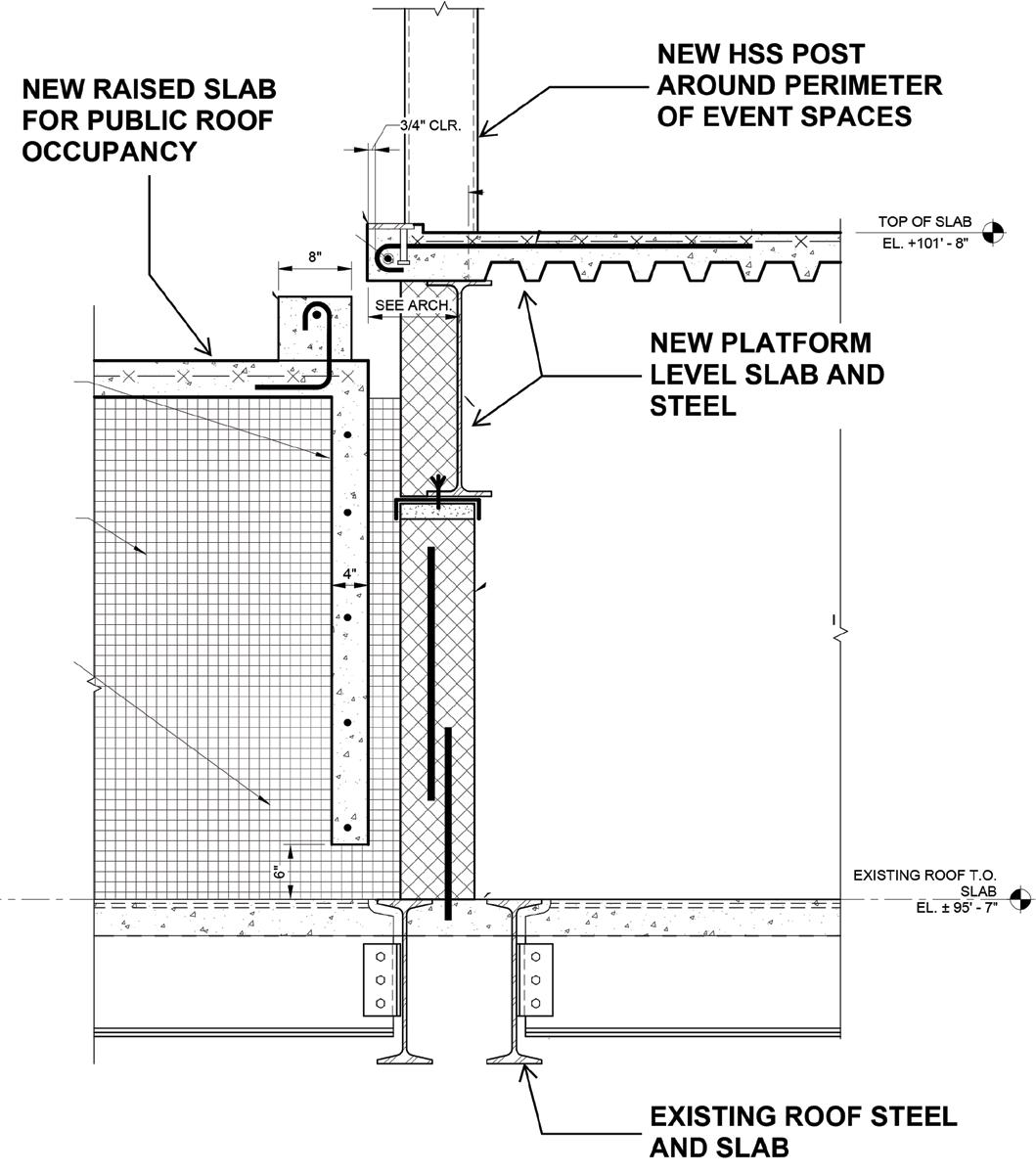
Structural Engineer: Silman Architects: Mecanoo and Beyer Blinder Belle MEP Engineer: Kohler Ronan Contractor: Tishman Construction Company/AECOM
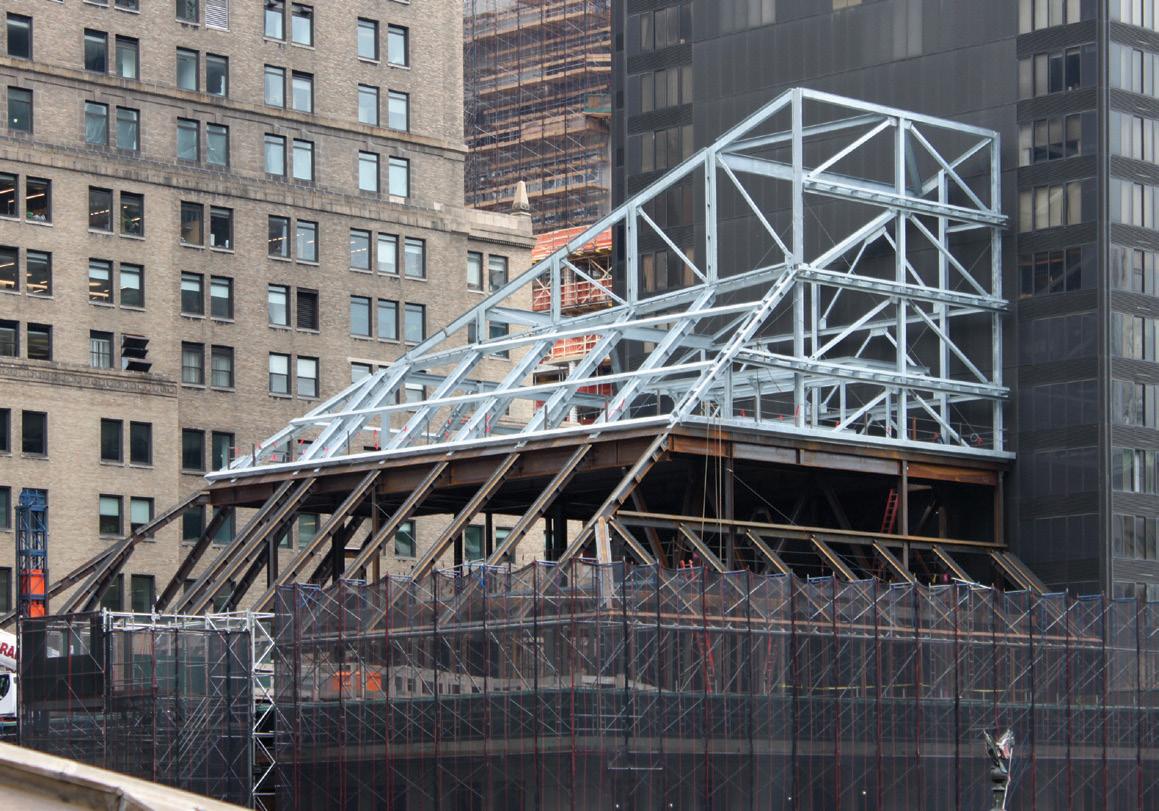
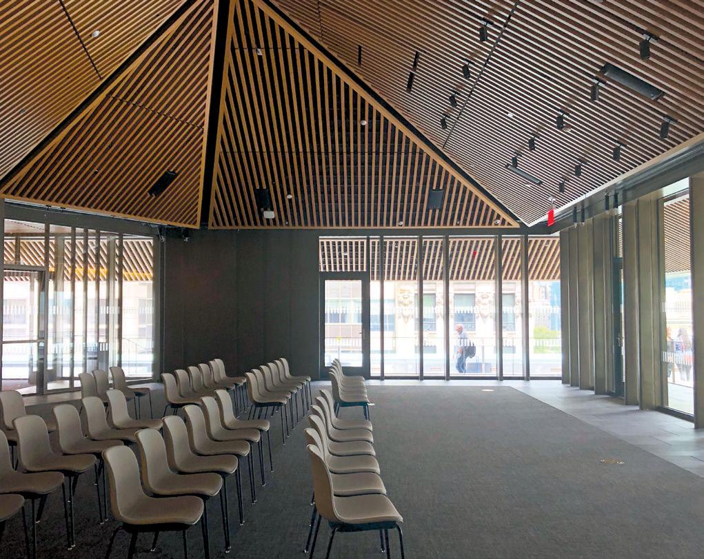
Rooftop addition under construction, as seen from the roof of SASB (NYPL’s main branch building). Courtesy of Paul Laroque.
Finished event space at new rooftop addition. New HSS columns are aligned with window mullions, creating a sizeable column-free space while providing two additional levels for mechanical and electrical equipment above.
Are clients (and the general population) aware of how the infrastructure behaves when subjected to extreme events, the risks, and the consequences – and, more importantly, if they are, do they care? One can answer these questions with a categorically confident: “It depends!”
Much is said and written nowadays about the need for resilience. If a societal goal is to achieve resilient cities – or a resilient world – everybody should be aware of the complex factors that make it difficult for society to prepare against disasters. And they should consider the patterns of human nature and technology that could ensure that these disasters will – or will not – repeat themselves. But, unfortunately, we are far from there yet.
A case in point is the 2011 Christchurch (New Zealand) earthquake. More than a thousand buildings in Christchurch’s Central Business District (CBD) suffered moderate damage during this earthquake. To structural engineers, these buildings performed as intended because the seismic design provisions in building codes aim to provide life safety by preventing collapse, not protecting the assets. However, the public was shocked to learn this, particularly as it watched more than a thousand buildings being demolished after the earthquake because their non-fatal structural damage was deemed prohibitively expensive to repair (or less desirable than rebuilding with insurance money). It temporarily turned the CBD into a ghost town, and reconstruction is still underway 11 years later.
Similarly and anecdotally, following Hurricane Ian, I posted an article on LinkedIn with a picture showing the devastation in Fort Myers Beach. In that photo, most oceanfront houses had been flattened by the wind and storm surge, except one that stood up defiantly with non-fatal damage (much like the one that survived Hurricane Michael, as documented in STRUCTURE’s March 2019 issue). Doing a bit of data-digging with Google Earth, Street View, real estate websites, and tax assessors’ records, it was possible to determine that this house had been constructed in 2022. In contrast, the other homes surrounding it had been constructed from the 1920s to the 1990s (information
I provided in a second post). In a week, the two posts were viewed by more than a million people, received 4,000 reactions, and generated more than 500 comments. In these comments, the engineers and home builders highlighted this as proof of effective progress in Florida’s Building Code (and its enforcement) that today requires a highly-elevated first floor, roof tie-downs, hurricane windresistant windows, etc. On the other hand, many non-engineers attributed it to sheer luck, the whims of mother nature, or divine intervention. A significant disconnect, to say the least.


A more knowledgeable public is a more resilient public, and this is where e Blessings of Disaster goes to work. e book targets the general public, although engineers can enjoy reading it too. It tells the real story of our relationship with disasters and how it could provide insights into our future as a civilization. It also aims to make everybody aware of all the traits of human nature and technological factors that challenge us when it comes to preventing (or not) disasters, which is a critical first step – a necessary condition. What must be done after that to solve the problems becomes complicated –and this is where engineers can use the book for leverage.
In creating safe and resilient infrastructure, all structural engineers are in the business of saving lives (“holding paramount the health, safety, and welfare of the public”). is is critically important because deaths occur when the infrastructure intended to protect us from the environment collapses during fault ruptures, stormy winds, water surges, technological failures, and terrorist attacks. Many engineers are part of the army
of silent heroes who work tirelessly behind the scenes to promote the development and adoption of enhanced codes and specifications to prevent or minimize the destruction caused by these extreme events – efforts often met with strong opposition (sometimes by engineers too). ese silent heroes progressively create a world that is more resilient to disasters, moving the needle to some degree, one nudge at a time.
However, for all hazards, nothing is as eff ective as a disaster. It not only moves the needle but also puts jet engines on it! Everybody cares about the issues for a short period after a disaster. One excellent option is to wait for a disaster to take advantage of this suddenly opened window of opportunity (and act fast because that window usually closes quickly).
Another (less painful) option is to use the book as a useful bridge to initiate discussions with clients on the exposure of infrastructure to disasters and the range of possible solutions. An engineer told me that e Blessings of Disaster is “not only a book that engineers enjoy reading, it is also a book that engineering fi rms might consider giving to all their clients.” Structural engineers are always ready to build new bridges – particularly if they lead to a more resilient society. As such, this may be one more tool worth adding to the engineer’s toolbox. ■
Michel Bruneau is a Distinguished Professor at SUNY Department of Civil, Structural, and Environmental Engineering and author of The Blessings of Disaster: The Lessons That Catastrophes Teach Us and Why Our Future Depends on It

People rarely get medals or rewards for averting a disaster … Yet safety is not magically happening by itself.
Arobust post-pandemic job market has triggered a high demand for design and construction expertise. In addition, an influx of federal funding further heightens demand.
At events such as the Winter or Summer ACEC Coalition Meetings, many executives from the industry’s top structural engineering firms often raise recruitment and retention concerns. Unfortunately, these challenges now confront firms of all sizes in nearly every region across the country.
Rather than try to out-recruit the competition, structural design firms should consider alterna tive strategies – from identifying the potential contributions of non-engineers to adopting Artificial Intelligence technologies – to meet our clients’ growing, increasingly complex needs.
to Bring New Talent into the Profession
Demand for structural engineers increases as the baby boomer generation hits retirement age. To backfill senior technical and leadership positions, firms often rely on engineers with 10 to 15 years of experience. But this demo graphic is unusually small as many young engineers left the profession 10-15 years ago during the Great Recession when entry-level positions were fewer in number.
There’s no single solution for how to recruit talent. However, increased salaries, better ben efit packages, internal and external training opportunities, flexible hours, and remote work opportunities are all effective.
But if most firms are looking to fill holes in their roster, recruiting talent from within the industry will not solve the overall talent gap. So, how can we attract new talent into the occupation? Or, how can we increase produc tion with current staffing levels?
Samuel C. Florman’s 1976 book, The Existential Pleasures of Engineering, describes the century from 1850 to 1950 as The Golden Age of Engineering. At a high level, engineering remains a respected and valued field – but the golden years are behind us.
U.S. Bureau of Labor Statistics (BLS) data shows that civil engineering salaries have tracked pretty closely with inflation, grow ing proportionally at the same rate as the salaries of other prestigious professions like
doctors and lawyers. For example, as shown in the Table, the Consumer Price Index rose approximately 960% from January 1960 to January 2022, while an average civil engineer’s salary rose 1076%. The picture is not so rosy, however, for the industry’s entry-level staff. The target demographic for many firms’ recruitment efforts is, on average, not compensated as well as their peers in fields that have recently experienced soaring profits. According to salary data compiled by Michigan Technological University, civil engineering graduates enter the workforce with a salary of $20,000 per year less than robotics engineers. In addition, they earn $16,000 per year less than computer hard ware engineers and $10,000 per year less than industrial and manufacturing engineers. When selecting a field of study, first-year engineering students are potentially deterred by these salary figures. Young engineers are, perhaps, more likely to seek alternative career paths if compensation cannot keep pace with the earnings of their peers.
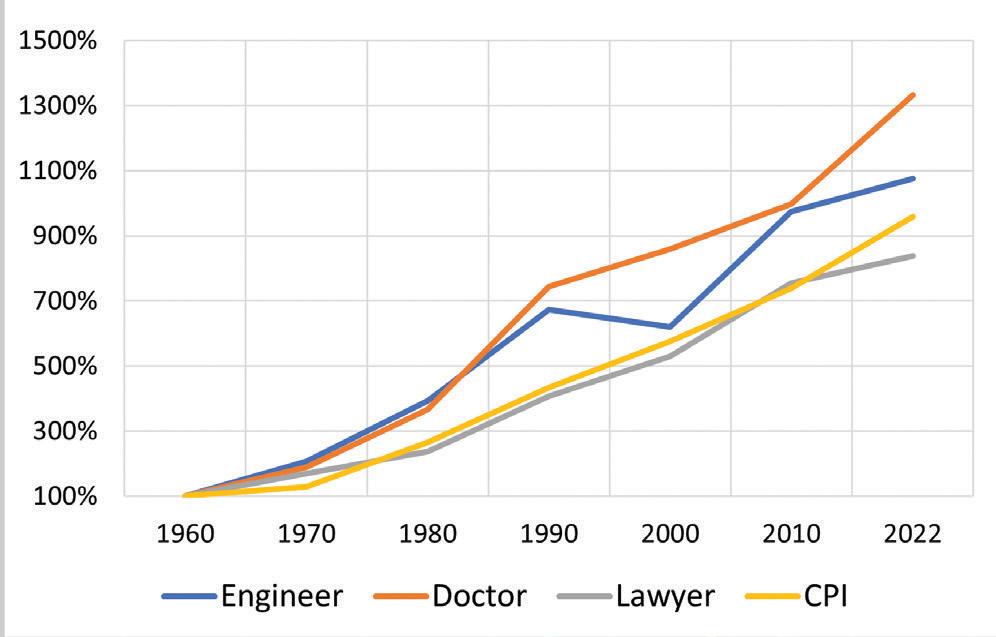
of average salaries over time.

can improve the accuracy, detail, and costeffectiveness of structural designs.
Many workforces bemoan automation as contributing to job losses. But AI systems and machine learning applications can enable structural engineering firms to maximize their resources. For example, faster and more-reliable calculations allow designers to shoulder greater assignments without becoming overburdened.
Do all staff members need to be trained, licensed engineers? Maybe we can grow our talent pool by recruiting problem solvers from other industries to fill certain roles. For example, it is common to hear that a recent civil engineering graduate took a job with a contractor or a promising young engineer left consulting to work in-house as an owner’s representative for a recent client. It is much less common to hear of a construction engineer joining an engineering firm.
Could a construction engineer be trained to lead a project’s construction services phase? Many already understand how to read engi neering drawings and know their way around a construction site. However, with proper coaching from the lead designers, constructionoriented staff members may be able to relieve licensed professionals from these duties.
Over the past decade, advanced processing capabilities have given rise to several logicbased Artificial Intelligence (AI) systems that
Training on emerging AI technologies is essential for many young engineers’ longterm career growth. By cultivating a culture of learning, structural design firms can keep their staff on the leading edge. In addition, employees who recognize that their company is truly invested in their long-term success are often more likely to stay put.
Structural designers have led the way through many of the engineering industry’s most challenging transformations. For example, structural engineers were among the first to adopt computer-based automated designs in the 1980s and to embrace building informa tion modeling in the 2000s.
The time has come to lead the way again. Visionary design firms can overcome recruit ment, retention, and performance concerns by embracing change. Forward-thinking firms who embrace the evolving nature of the industry can demonstrate their added value – to recruits, employees, and clients – and position themselves for growth for generations to come.
■
Anthony H. LoCicero III is a Project Manager at Burns Engineering, specializing in structural engineering analysis, design, and rehabilitation of complex structures in the public realm (alocicero@burns-group.com).
Altair
Phone: 604-273-7737
Email: manishaw@altair.com Web: www.altair.com/s-concrete
Product: Altair S-CONCRETE
Description: S-CONCRETE quickly and accurately designs reinforced concrete column, beam, wall sections, and continuous beams to regional code requirements. Versatile and easy-to-use for any project workflow, users save time by automatically checking thousands of concrete designs at once to produce comprehensive design reports.
Phone: 303-309-9444
Email: help@clearcalcs.com Web: www2.clearcalcs.com/retainingwallcantileverUSA
Product: Cantilever Retaining Wall Calculator to IBC 2018, ASCE 7-16
Description: ClearCalcs offers fast, customizable cantilever retaining wall design and analysis calculations for IBC. e easy-to-use interface makes it effortless to input your soil report information or use presumptive values if you do not have access to a soil report. Try it for free for 14-days at https://bit.ly/3SJxt05.
ENERCALC, Inc.
Phone: 800-424-2252 Email: info@enercalc.com Web: https://enercalc.com
Product: ENERCALC / Retain Pro
Description: For 30+ years, RetainPro provided time saving tools for analyzing and designing nearly any type of earth retention structure. Concrete and/or masonry, cantilevered or restrained, gravity walls, segmental walls with/without geogrids, soldier pile, gabion. Handles multiple loading conditions and stem designs. Today, these tools are included in your ENERCALC subscription.
IES, Inc.
Phone: 800-707-0816 Email: info@iesweb.com Web: www.iesweb.com
Product: IES VisualFoundation
Description: You need rock solid foundation design. IES offers easy structural software, like VisualFoundation. Quickly model mat slabs, pile caps, and grade beams. Get stability checks, handle punching shear, and make smart codecompliant designs. Try it free, watch videos, find product benefits and pricing at website.
Product: IES QuickRWall
Description: Design retaining walls? Try QuickRWall and generate 16 pages of hand calculations and sketches of your design. You simply specify the wall, soil conditions, and other loads. Get instant feedback on pass/fail status, see details of all checks. Start making money on your designs with QuickRWall from IES.
Listings are provided as a courtesy, STRUCTURE is not responsible for errors.
Phone: 949-951-5815
Email: candicec@risa.com Web: www.risa.com
Product: RISAFoundation
Description: Designs retaining walls, two-way mat slabs, spread footings, grade beams and pile caps all within an open modeling environment. Create retaining walls in RISAFoundation and add line loads to them as well. RISAFoundation's user friendly interface creates retaining walls graphically or through spreadsheets.
Phone: 678-737-7379
Email: jodi.hendrixson@trimble.com Web: www.tekla.com/us
Product: Tekla Tedds
Description: A powerful design program for automating wind and seismic calculations and performing member designs. Tekla Tedds features a built-in library of calculations for quickly calculating ASCE 7 wind and seismic forces for any structure and component design modules, beams, columns, and foundation designs. Modules can be linked.
Product: Tekla Structural Designer

Description: Designing a lateral force-resisting system has never been easier with Tekla Structural Designer's codebased 3-D BIM analysis and design tool. Built-in loading wizards automatically calculate all wind and seismic forces, generate design cases, and optimize the design of steel and concrete members to the latest design codes.
Williams Form Engineering Corp.
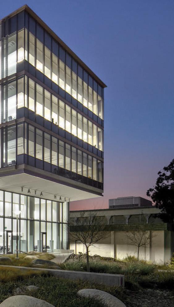

Phone: 616-866-0815
Email: williams@williamsform.com Web: www.williamsform.com
Product: Anchor Systems
Description: Williams Form Engineering Corporation has been providing threaded steel bars and accessories for rock anchors, soil anchors, high capacity concrete anchors, micropiles, tie rods, tiebacks, strand anchors, hollow bar anchors, post tensioning systems, and concrete forming hardware systems in the construction industry for over 100 years.
Employer www.kpff.com


The NCSEA SEA Grant Program awards SEAs funding for projects that advance their SEA and the structural engineering profession in accordance with the NCSEA Mission Statement. Supported by the NCSEA Foundation, the SEA Grant Program has delivered more than $70,000 in grants since its inception! Here are the 2022 winners and their projects.
Structural Engineers Association of New Mexico (SEANM)
Continuing Creation of the Young Member Group (YMG)
SEANM started a YMG about a year ago. YMG aims to spread the word that there is an active structural engineering community here in NM and provide resources for young engineers. The YMG of SEANM’s goal is to support practicing young structural engineers. They aim to provide various resources to advance career growth and development and assist in becoming highly qualified professionals. They are beginning to offer mentorship programs with senior structural engineers and offer technical advancement opportunities. They also hope to provide young engineers leadership and soft skills advancement opportunities.
Structural Engineers Association of Southern California (SEAOSC)
In December 2022, SEAOSC will host the Southern California Gingerbread Challenge, a design and construction competition. This event will have 30+ teams of engineers, architects, and construction officials working throughout one day to build gingerbread structures to demonstrate the engineering and design industry. Utilizing tabletop shake tables, this is a hands-on (and edible) outreach activity that will engage students and introduce them to the A/E/C industry with an emphasis on building stability. Youth will not only have a chance to tour the mesmerizing gingerbread structures on display but also be able to build and then shake their very own creations.
Structural Engineers Association of Texas (SEAoT)
Student Member and Young Member Group Outreach, Engagement, and Growth SEAoT’s project will increase the organization’s visibility on college and university campuses in Texas that provide degrees in structural engineering. Th eir plans for 2023 are to recruit and engage new members to this group. Funds will be applied to launch social media campaigns to increase awareness and visibility of SEAoT, host live networking events on campus and at the annual convention, and build a mentorship program. Th is project will advance the mission of NCSEA by piquing the interest of young members and students to join the organization.
Structural Engineers Association of Southern California (SEAOSC)

In March 2023, SEAOSC will host its reimagined Emerging Leaders event, which will be year two of the program launch for an expanded mentorship program, an opportunity to recognize student scholarship winners, and a skill-building program that will provide emerging and established leaders with essential communication and networking tools to accelerate their success. This program will help establish a foundation for our emerging leaders and reinforce best practices for more experienced members.

follow @NCSEA on social media for the latest news & events!


e SEAOSD Business Forum Committee plans to work with adjacent industries and develop a true network for senior leadership, midlevel management, and entry-level engineers in the area. e BDC was created to cater to small business owners with monthly committee meetings and quarterly presentations from supporting industries (Financials/Accounting, E&O Insurance, Business [Path to Principal], etc.). e quarterly meetings will supplement core committee efforts and offer networking, guidance, and collaboration with other committees and industries. e goal is to promote a “rising tide” mentality amongst San Diego structural engineers and perform as an aspirational committee to attract new engineers, undergrads, and non-member local firms.
The NCSEA Foundation is proud of its accomplishments in 2022 through the annual SEA grants program and the Diversity in Structural Engineering college scholarships.The NCSEA Foundation strives to advance the science and practice of structural engineering by supporting NCSEA, the state SEAs, and practicing structural engineers. The generosity of our donors makes it possible for the Foundation to enhance inclusion in the industry, enable important research, support young professionals and provide grants to SEAs for future innovation. Scan this code to learn more about the work of the NCSEA Foundation and consider donating as we look forward to growing our initiatives in 2023!


Visit www.ncsea.com/education for the latest news on upcoming webinars and other virtual events.

As demand for mass timber buildings continues to rise throughout the country, cities and states are early adopting the 2021 International Building Code (IBC) mass timber provisions, which expands the use of wood construction from 6 to 18 stories. There are over 1,000 projects throughout the nation that are using mass timber under the previous code provisions or the 2021 IBC provisions. This webinar series will include an introduction to mass timber, an overview and design examples of CLT diaphragm and shear walls, and fire resistance design for mass timber.
Purchase an NCSEA webinar subscription and get access to all the educational content you’ll ever need! Subscribers receive access to a full year’s worth of live NCSEA education webinars (25+) and a recorded library of past webinars (170+) – all developed by leading experts, available whenever, wherever you need them!
Courses award 1.0-1.5 hours of Diamond Review-approved continuing education after completing a quiz.


January 25, 2023, Noon – 1:00 pm ET
Includes purpose and use of the ASCE 7 Hazard Tool with updated ASCE 7-22 data and an additional overview that ties in seismic and flood hazards. e ASCE 7 Hazard Tool is a web-based application that is easy to navigate and provides a quick way to look up eight environmental hazards for a specific location, including wind, tornado, rain, flood, snow, ice, seismic, and tsunami. Generate a summary and PDF report of the data that can be used in engineering proposals.
e Hazard Tool is free to the public.
Learn more and register at https://mylearning.asce.org/diweb/catalog/item?id=11025178

e SEI Standards Series continues focusing on ASCE 7 & the Building Codes, two new SEI Standards, and ASCE 7-22 and the IBC 2024 Update. Each program will include a dialogue between industry leaders and experts and a detailed technical presentation, and attendees will be encouraged to join the discussion for the extensive live Q&A portion.
• February 9, 2023: ASCE 7 & e Building Codes (Part I)
• March 9, 2023: ASCE 7 & e Building Codes (Part II)
• June 8, 2023: ASCE/SEI 76 – Disproportionate Collapse
• September 14, 2023: ASCE/SEI 41 – Seismic Retrofit
• October 12, 2023: ASCE 7-22 & IBC 2024 Update
Learn more and register at https://collaborate.asce.org/integratedstructures/sei-standards

ASCE 7 is accepting new members for the 2028 edition. Apply by December 18 at asce.org/asce7.
ree standards are open for new member applications: ASCE 24 Flood Resistant Design and Construction, ASCE 49 Wind Tunnel Testing, and ASCE 72 Design of Steel Lighting System Support Pole Structures. ese standards are now accepting new members for the 2028 edition of the standard. Apply at www.asce.org/SEICommittees until January 15.
Join SEI as a Sustaining Organization Member to reach SEI members year-round, and show your support for SEI to advance and serve the structural engineering profession. www.asce.org/SEI
Elite: www.se2050.org


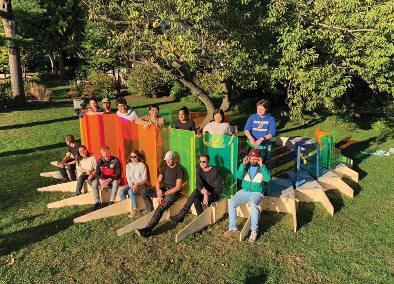

Earlier this year, a team of dedicated students and young professionals, in collaboration with Grimshaw Architects, schlaich bergermann partner, and Hofstra University, ran a successful design-build workshop and construction project with funding support from the SEI Futures Fund. e project, an adaptation of projects by Scale Rule in the UK, organized the workshop, design process, and construction to inspire students and nurture the creativity, understanding, and problem-solving skills at the core of structural engineering practice. Project goals included learning collaborative interdisciplinary design and communication skills to encourage more engineers, more diverse engineers, and engineers with a changing skill set.
Twenty-four high school students, invited through their schools and youth organizations, attended the workshop at Hofstra. e program included presentations on the AEC industry, key principles of a structural load path, and architectural sketching. Student teams were challenged to develop a concept design for an interactive pavilion to install on the Hofstra campus, working closely with Hofstra engineering students and industry volunteers to develop sketches and a physical model of their design. Finally, they presented their creative concept designs to a panel of judges from industry and academia, who selected the design for a bench wrapped around a tree with colorful translucent screens.
e workshop volunteers iterated the design to match the construction budget and schedule, explored reused and secondhand materials, and favored design detailing that enabled automated fabrication to allow simple assembly on site. e focus on precision bending and cutting from the material suppliers allowed the design team of young professionals and university students to install the pavilion in less than eight hours. e whole project – from the workshop to the construction of the pavilion – was completed in less than six months.
e project enabled university students and young professionals to share their design insights with a diverse group of high school students. e design process allowed young professionals to engage in engineering on a different scale and level of detail than their typical project work, taking responsibility for material procurement and construction scheduling. e construction process provided young professionals and university students insight into the complications of effectively realizing calculations and designs into physical construction. Following completion of the pilot project, a resource and instruction guide will be made available as a model for other groups to replicate the program with industry, university, and high school partnerships. Learn more at https://scalerule.org/building-the-next-engineers.
to support the Future of Structural Engineering with your year-end giving.
The CASE ExCom received a briefing from Dan Hilton, ACEC’s Director of Procurement Advocacy & International Affairs, on current legislative issues, discussed feedback we are receiving on our editorial on NCEES’ new CBT Structural exam, and upcoming magazine assign ments. The Contracts committee will be preparing a white paper on teaming agreements. The Programs committee finalized the upcoming Business of SE Boot Camp Nov 1st in Chicago for which we partnered with NCSEA. See a report on the Boot Camp below.
CASE hosted a Roundtable jointly with our friends at CAMEE. Attendees wanted to discuss every firm’s most valuable resource - employees! Topics included best practices for keeping employees, compensation, leadership development, mentoring/onboarding (especially remote workers), and hybrid work environment. Attendees also expressed that the demand for structural engineering services remains strong, and firms are maintaining a backlog of work.
CASE also sponsored session on mergers and acquisitions, and the influx of private equity into the engineering market. It’s great to see our member firms have such value!
The 2022 Business of Structural Engineering Boot Camp: Communications, Claims &Contracts was held on November 1, 2022, in Chicago. The three-part session included Examining Claims: Lessons Learned for SE Leaders by John Tawresey, S.E., Chief Financial Officer, KPFF Consulting Engineers; a communications session on Having Hard Conversations and Coming Out on Top by Marc Warren, President and Co-Founder, Customer Follow Up, Inc. and concluded with Why is Legal Advice about Contracts like Twinkies and Cockroaches? which was presented by Karen Erger, Senior Vice President, Director of Practice Risk Management, Lockton, and Eric Singer, Partner, Ice Miller, LLP.
Examining Claims: Lessons Learned for SE Leaders highlighted that sharing actual claim experiences is the single most powerful tool available to practicing professionals. Sharing can promote the professional learning process and help other firms avoid making those same mistakes repeatedly. In addition, this sharing provides structural engineers with practical information that allows them to implement loss prevention tactics and practices.
Having Hard Conversations and Coming Out on Top showed attendees how to prepare themselves to have successful, hard conversa tions and how those conversations can be instrumental in positioning a firm for positive project outcomes and long-term successful client relationships without simply giving clients everything they ask for.
In the day’s final session, Why is Legal Advice about Contracts like Twinkies and Cockroaches?, attendees took a deep dive into service agreements and the importance of well-written contracts. As the presenters pointed out and reiterated throughout the afternoon, while bad contracts do not cause claims, they can make claims much worse and harder to resolve.
If you are looking for similar educational content, you are encouraged to attend the ACEC Spring Convention and Fall Conferences, occurring every year. Each year CASE sponsors a series of educational sessions at ACEC events that are similar in content. These events are open to all attendees.
Engineering Influence is the official award-winning podcast of ACEC. CASE Chair, Kevin Chamberlain, joined the podcast during the Fall Conference to give an update on CASE activities and the issues facing structural engineers. Hear what he had to say!
Do you know someone in your firm looking to expand and strengthen their business skillset, gain experience serving on a committee, sharpen their leadership skills, and travel to interesting places? Then, please consider applying for a position on the committee. Committee member commitments include a monthly virtual meeting, working on relevant documents a few hours a month, and traveling to the winter and summer Coalition meetings!
To apply, your firm should:
• Be a current member of ACEC

• Be a member of the Coalition of American Structural Engineers (CASE), or be willing to join the Coalition
• Be able to attend the groups’ regular face-to-face meetings each year: August, February (hotel, travel partially reimbursable)
• Be available to engage with the committees via email and video/conference call
• Have some specific experience and/or expertise to contribute to the group
CASE has a library of tools and practice guidelines to help firms deal with a wide variety of business scenarios that structural engi neering firms face daily. So whether your firm needs to establish a new Quality Assurance Program, update its risk management program, keep track of the skills engineers are learning at each level of experience, or need a sample contract document – CASE has the tools you need!
Check
Out!
Beyond the Code: Grade-Level Floors over Expansive Soils – CASE recognizes that the International Building Code and other governing codes do not address all aspects of structural engineering and design. Often, the most common issues where the owners, contractor, or design team are not aligned deal with what is not clearly addressed by the various codes or design guidelines. This is the first in a series of Beyond the Code white papers that collate design considerations that need to be discussed with the owners at the beginning of a project to establish a clear Basis-of-Design. By proactively bringing up the design consideration in front of the owners, the Structural Engineer can set realistic expectations and discuss the cost impact of alternative designs.
This first white paper in the Beyond the Code series discussed the pros and cons of two structural design options for the grade-level floor in expansive soil regions. Keep an eye out for future installments in the series!
What’s Shaking? A new publication from CASE about Seismic Design
CASE Guideline 962- J – Business Practice Guidelines of Seismic Design for the Structural Engineer. The purpose of this document is to provide insights into structural engineering services in regions where there is a seismic hazard. This document shares key design considerations as well as business practice considerations. Numerous resources are available that provide a much more exhaustive and advanced technical presentation of important considerations when designing for earthquakes. Someone new to designing for earthquakes should consider taking a course in structural dynamics and seismic engineering, whether from a university or some other provider such as ASCE or NCSEA.
You can purchase these and other Risk Management Tools at www.acec.org/bookstore You can also browse all of the CASE publications at www.acec.org/coalitions/coalition-publications Is there something missing for your business practice? CASE is committed to publishing the right tools for you. Have an idea? We would love to hear from you!
If you are a CASE member, this tool and all publications are free. NCSEA and SEI members receive a discount on publications. Use discount code – NCSEASEI2022 when you check out.
Your monetary support is vital in helping CASE and ACEC increase scholarships to those students who are the future of our industry. All donations toward the program may be eligible for tax deduction and you don't have to be an ACEC member to donate!
Donate today: www.acecresearchinstitute.org/scholarships

Congratulations to the 2022 CASE Scholarship winner, Taylor Drahota, from the University of Nebraska-Lincoln! View information about the scholarship and win ners at acec.org under “Awards.”

Invest in the future of our workforce. Donate to the CASE Scholarship fund!


When it comes to impeding homebuilding growth, one does not need to look further than global supply chain issues. Closures in factories and transportation hubs have negatively affected an industry that relies on building materials sourced throughout the world. And while there is certainly no shortage of new housing demand here in the United States, there is a scarcity of the essential materials needed to build these dwellings.
As one might expect, supply chain challenges have led to extensive construction delays and higher building costs, which are passed on to the consumer. According to e Wall Street Journal, supply-chain backlogs, combined with inflationary pressures, have sent new home prices skyrocketing to record levels. In November 2021, the cost of a newly built home was just under $417,000 – a staggering 19% jump from the previous year.
Housing market research firm Zonda indicates that 90% of home builders recently surveyed admitted their business was significantly affected due to supply chain delays – forcing them to reschedule the few skilled workers available until much-needed materials could be acquired. It is not just new home construction that has been adversely affected by supply chain issues; home renovators must also find ways to navigate prolonged wait times for vital materials and home furnishing deliveries.
e National Association of Home Builders states that the total cost of construction in the United States has grown by 21% over the past year. Delivery delays and the steep rise in lumber costs are among the main reasons for this dramatic increase. “Supply chain issues are continuing to impact all levels of construction, not just the construction of new luxury homes or developments,” said Ken Colao, president of CNY Group, a construction and development services firm in New York.


As the construction industry continues to contend with delays and price surges resulting from material shortages, a growing number of designers, contractors, and developers are turning to alternative resources to save money and get the job done in a timelier manner. Swapping cement with other materials that have similar properties and reusing materials that would have otherwise gone to waste, such as those extracted from demolition sites, are
just some of the less traditional approaches builders are now implementing. Another example of alternate materials used for the construction of homes and offices includes the application of natural materials such as adobe brick, volcanic rock, and rammed earth. ese materials are readily available on-site and offer added cooling and heating benefits from the natural insulation they provide. However, while developing alternative materials like these is often tied to sustainability efforts and has been demonstrated to be advantageous during a supply chain crisis, they can also present potential risks.
ere are downsides when it comes to using these types of building materials. Greater expenses for experienced, skilled labor are among the biggest hurdles to overcome, along with delays brought on by home inspectors who may lack the insight and understanding of building a home with these alternative materials.


Perhaps the most significant threats these alternative materials pose to construction workers and home residents are long-term health effects, primarily those stemming from mold. Unfortunately, earthen materials like those identified earlier have been shown to have abundant organic substances that can harbor mold – a costly liability concern for property owners and builders.
Wherever there is moisture, a lack of ventilation, and the right temperature range, mold
can often be found. Once it spreads within a home, the damaging health effects can be severe. To prevent mold, it is imperative to identify the association between construction materials and their vulnerability to mold when any type of moisture is present.
“Buildings will never be designed, built, maintained, or utilized perfectly, and weather and natural disasters cannot be predicted. e one thing we have complete control over, the materials within the building, should be selected wisely,” said Aaron Cooper in his Texas A&M master’s thesis on mold susceptibility of rapidly renewable materials used in wall construction.

e existence of toxic mold brought on by alternative building materials, like adobe brick and rammed earth, often implies an underlying construction defect and, thus, frequently leads to litigation. It should be noted that toxic mold lawsuits can be complex and call for expert medical and scientific testimony. However, most of these grievances against landlords and building owners are settled before trial.
Toxic mold is one instance of the potentially harmful effects of using alternative materials. Taking the time to better understand all aspects of various building material options can help dismiss non-compliant materials while also helping to lessen costly disputes and returns.
■
Slawomir Platta is the Founding Partner at The Platta Law Firm, PLLC. He has been trying construction accident cases throughout the Courts of New York for almost 20 years and consecutively featured as a Super Lawyer since 2015.
...a growing number of designers, contractors, and developers are turning to alternative resources to save money and get the job done in a timelier manner.


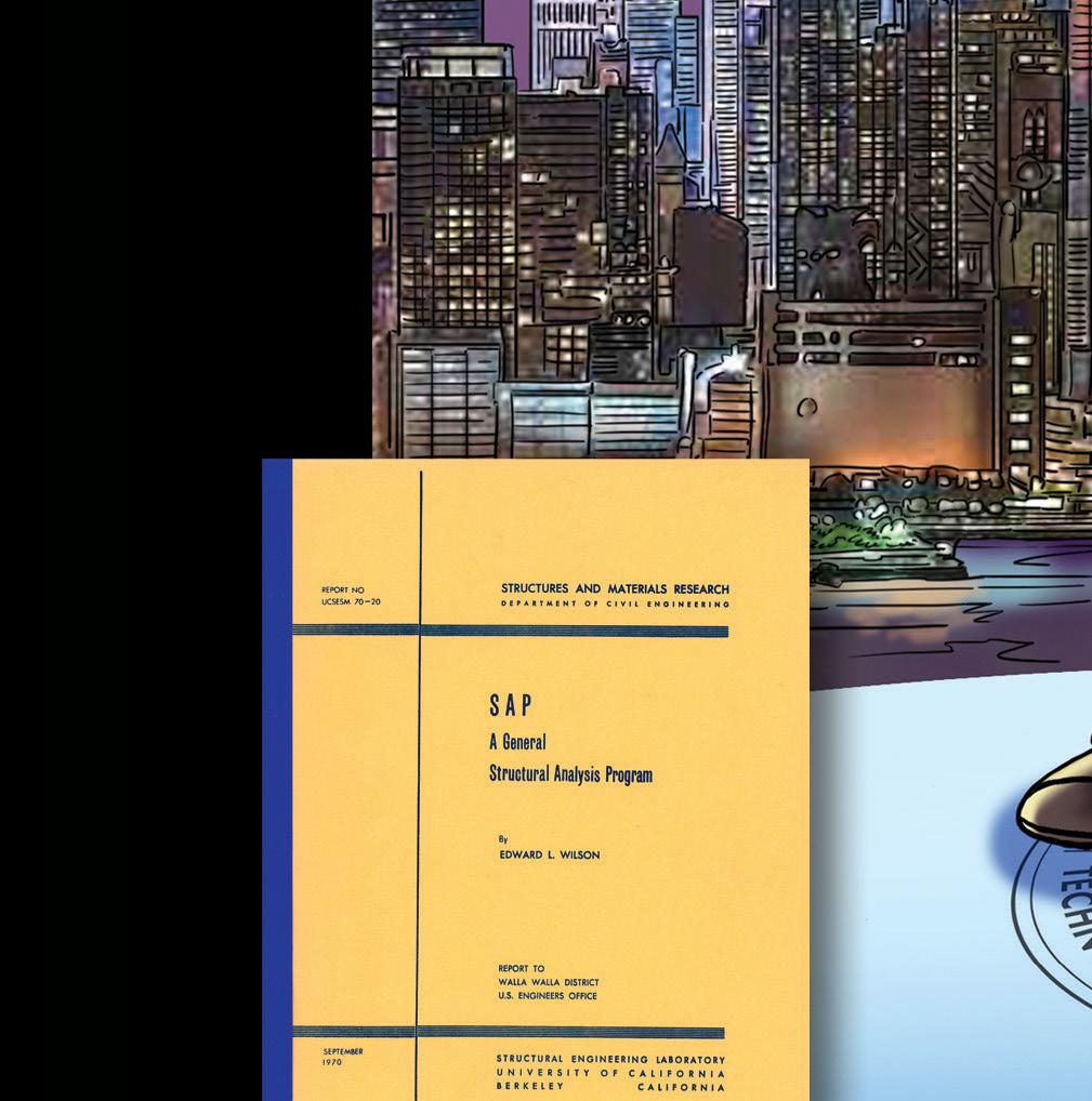


Spanning the decades, encompassing the globe!
As we celebrate 50 years of innovation that have made SAP2000 what it is today, we would like to recognize the immeasurable contributions of Professor Edward L. Wilson, Professor Emeritus at the University of California at Berkeley, who started it all by launching the first version of SAP in 1970.
THANK YOU, ED!