I have wanted a REU for my Commodore 64 and 128, but they haven’t been reasonable to get an original. I also has not seen a reproduction option. Yes there are a few options, but nothing I was going to get into. I recently came across Frntc’s RAD Expansion Unit Project. I recently saw the Sidekick64 and had been wondering what it was, what advantage does it have to other similar products. It turns out in the US you can’t buy built versions of his projects (short of shipping and fees from Europe). If you are in Europe there are authorized resellers of the RAD Expansion Unit.
The RAD EU uses a Raspberry pi, either a Pi3 or Pi Zero2 to emulate a REU / Ram Expansion Unit. It can work at various sizes up to 16Mb, it can also work as Georam. It can do REU Images, which I am not familiar with, and NUVIEs and says it can run PRG. I take it the PRG is normal PRG files. NUVIEs are 16mb movie files which I have not tried. My intention for this device is to use it as a REU to run some programs I couldn’t otherwise run on my Commodore 64 / 128. I am thinking of trying out Geos as well with it.
Frntc has released the Gerber files for getting PCBs produced. It is highly recommended to get the Gold Plated ENIG boards. While the HASL Solder coated fingers are very common, they are common because they are cheap, not because they are recommended. Most or even all of the aftermarket Cartridges I have are HASL, they generally work, but use of them makes the solder rub off into your cartridge slot and will cause problems over time. The boards I had produced awhile ago were also HASL. I hadn’t been having issues with them on my C64, but I don’t swap cartridges often. I did find my C128 was very unreliable using the cartridges, which may be due to another reason.
I had a spare Pi3 A+, I do also have a single Pi Zero2, but I felt it is more useful for some other projects. I ordered up Frntc’s board design for the pi3 model with the Gold Plate ENIG board finish.
The gold looks very nice. It is a much more constant finish on the edge connecter. I can see how these boards are certainly an upgrade for edge connector boards. For boards without the edge connector I will keep using the HASL finish. It is generally a difference for example from $2 to $19 for a small batch of boards.
Frntc provides a file call ibom.html in the Gerber folder that is an interactive Bill of Materials. It lists the basic part and footprint data for it. I wish he had used more universal footprints, some of these surface mount footprints can be setup to accept either the wider ics or the narrower ICs giving more valid part options. It took me awhile looking at the parts on Digikey and Mouser to find the ICs with the proper footprint for the boards.
I found all the right parts eventually. I was going to order from Digikey, but they didn’t have one of the ICs in stock. I went with Mouser as they had everything in stock. The pricing was generally close between the two suppliers. I did mess up and miss ordering some of things I had sitting in a cart at Digikey that I wanted to put on my next order though.. The parts all came in and it turns out everything was correct. I will list the specific Parts I ordered here.
1 Mouser #:771-74LVC245AD-T Mfr. #:74LVC245AD,118 Bus Transceivers 74LVC245AD/SOT163/SO20
2 Mouser #:595-SN74LVC573ADWR Mfr. #:SN74LVC573ADWR Octal Trans D-Type Latch
Notes: The 10k Ohm resistors are 0805 parts not 603 an oddity in the part number I guess.. The Capacitors are all 0805 as well. One of the HTC30 ICs and it’s capacitor are not listed as required on the ibom. I found a picture of the board where that IC is outlined in the silkscreen as “optional”. I put them on, I wonder if it is for debugging or development? It was $0.45 in parts basically, so I didn’t see a major reason to not install them.
I had an issue with the firmware. I figured it would be in the repository where it would download with it repository. That is how it has been for the few other projects that I have used. The code is in the repository if you download it, but not the compiled release. I am not very familiar with Github, maybe no one else will have an issue finding it without this little note. It turns out Releases are along the right hand side bar on Github. Since I had the issue finding it, I asked 8-bit Resurgence where the files were. So to get the compiled files, Click on “Releases” at the Github project page on the right hand bar, assuming they don’t change the location.
Test FitStickySticky
The soldering wasn’t too bad. I did try a new solder tip with the solder cavity in it for drag soldering. I found it was putting down to much solder and was difficult to remove a bridge with. I went back to my normal tip without the hollow in the bottom of it. I did use a paste flux, which I find is important for surface mount soldering, it helps clear and prevent bridges. I did find cleaning up the flux with 91% ipa wasn’t the easiest. It just didn’t do a great job and took a few passes. There was flux stuck inside the pi Header, you may be able to see it on the picture above still in the header. The next day I used contact cleaner on the header and ics. It flushed a lot of the flux out of the header, it also flushed a lot of flux out from under the ics that I didn’t know as still under there.
It works.
Now it needs a case. There is a case design linked with the project. I started printing it in a slightly translucent blue PLA. The label on it was printed on plain paper as a test with double sided tape on the back. Overall the case looked pretty good, it also fit well. I decided I wanted something that blended more with the Commodore 64.
I ordered in Polymaker Matte PLA 1.75mm Muted White Filament to see how that looked. It was recommended by Macintosh Librarian as a good matching color for the early Macintosh. I figured it will not be a perfect color match, but it should be in a good color range to “fit in” better than the blue case.
I also had a small piece of Inkjet Vinyl. My old HP Inkjet printer is out of black ink, and the new color cartridge isn’t working well, probably due to how old it is even though I just installed it. It is also quite an old printer that Windows 10 doesn’t care to print to it properly. I had to tape the small piece to a piece of paper to put it through the printer. Which it did well with that. I’m debating buying fresh cartridges for it.
I like the new case a lot better. The label is much nicer too. I like the color, it is a light beige. It is not a “match” to the Commodore 64 Breadbin color, it is probably fairly close to the Commodore 128 or Commodore 64C. I can’t tell though, as my Commodore 128 is Yellow.. The Commodore 64 Breadbin I am using it in is lighter than the typical Breadbin because it has been Painted. The RAD EU is a bit lighter than the paint, but looks very nice with it. I did print the case at .28mm layer height, so printing at lower layer heights may make a little nicer looking case.
I have tried it with Nuvies as well, but the are almost exclusively PAL based, which won’t work on NTSC computers. I did then end up importing a PAL C64c, which is works well with and can play the PAL Nuvies.
Updated 8/13/23: I switched the U34 and used the J4 Bodge wire to A15 and have updated instructions and pictures below to match.
I have been wanting to put JiffyDOS on my Commodore 128. My 1541ii came with JiffyDOS, but none of my Commodore Computers have the JiffyDOS ROM to match. I recently purchased JiffyDOS from RETRO Innovations, I purchased the ROMs for my Commodore 128, as well as for one of my Commodore 64s and a 1541 ROM to use on my pi1541.
The Commodore 128 Flat model shipped setup with 16k ROMs, but it can be switched to use 32k ROMs by setting some jumpers. If you switch it to 32k ROMs, then there are only 2 ROMs required instead of 4. The ROMs that shipped in the Commodore 128 Flat model are also older versions than what is available. I wanted to update to the latest version of the Basic ROM, and the Kernal as well, so it is nice to only need two eproms instead of four.
Note: I originally used the 390393-01 ROM for U34 and put a jumper on J4. I had issues loading programs from Disk, while some programs would load properly numerous ones would not work. I don’t know if there were other issues or not. Mark from TheRetroChannel on Youtube did the 32k ROM mod on his 128 and reported having issues with closing J4, it turns out to be the same type of issue I thought I was having too. He reported that when using the regular DCR ROM and the J4 bodge wire as shown at the rift.dk post, that he didn’t have any problems. I went back and have switched to doing that as well. I haven’t come across any disk reading issues after following the rift.dk J4 bodge wire method. I would like to know why that seems to have been an issue, the 390393-01 ROM having a part number like that means it is made up or a legitimate release from Commodore for the 128. I am expecting it throws off some timing off somewhere.The result I ended up with the dupont cable looks neat enough, but it still is a “bodge”.
In this case I am going to switch to the 32k ROMs, and also install a Switchless ROM Switcher with JiffyDOS. So this is a combination of a few mods.
To change the Commodore 128 Flat from 16kB ROMs to 32kB ROMs we just have to install jumpers or bridge J3, a bodge wire to one of the J4 pads and a via nearby, and J6. I am going to put in Jumpers and pins to make it easy to switch back if needed.
To setup the 32K ROM Set. We pull U33 (16k) and U34 (16k) and install the 32k U34 to replace them. That new ROM is the basic.318022-02.bin (32kB).
The second ROM we pull the 16K U32 and U35. Since I am doing the JiffyDOS Switchable ROM, I am making a 64K ROM to replace the original U32.
For the Switched C128/C128DCR KERNAL ROM (64kB) we combine the files below in this order: basic.901226-01.bin (C64 Basic) kernal.901227-03.bin (C64 Kernal) kernal.318020-05.bin (C128 Kernal) basic.901226-01.bin (C64 Basic) JiffyDOS_C64_6.01.bin (C64 JiffyDOS Kernal) JiffyDOS_C128DCR_6.01.bin (C128 JiffyDOS Kernal)
There are different ways to combine the files. I just use the copy /b Binary combine from Command Prompt: (Note as one single line)
Then burn the combined ROM to a 64k Eprom such as the 27512. The Commodore 128 uses the 27256 Pinout in 32k ROM Mode (and 27128 in 16k ROM Mode), so they are drop in replacements.
To do the Switched ROM we keep Pin1 (A15) bent out, and not inserted in the Socket. If I was going to do a Kernal “Switch”, then I would wire a 4.7k (recommended value I found) Resistor from Pin1 (A15) to Pin28 (VCC). Then put a switch between Pin1 and Ground. I am going to use an Arduino Pro Mini, it will not need the Pullup Resistor. I expect you could do Kernal Switcher that does more than two modes by making a 128K ROM, but for the Commodore 128 I don’t know of other Kernals that I care to use. That would also be a 32PIN Eprom, so an adapter would also be required. If you did stick with the 16k ROMs, you could then alternately use 64k Eproms to setup a 4 way ROM Switcher.
I am basing the Arduino Pro Mini code on a modified version of Adrian Black’s C64 Kernal Switcher that was done by Mark Ormond. I am starting with Mark Ormond’s modified version of the code as the basis. He had it setup for swapping 4 ROM Sets for 16k ROMS, but I only need to trigger a single pin (A15 Pin 1) on my JiffyDOS 64k U32. It was setup to control 2 Eproms and rotate through more ROMs triggering several Address lines as he was using 16k ROMs.
The Arduino board will be triggering A15 on the 64k ROM triggering it to use either the upper or lower 32k portion. It will also be wired to the ResetLine, EXROMLine and RestoreKey, as well as Ground and 5V.
The PowerLED will also be moved to the Arduino board with a proper current limiting resistor (220 Ohm typically) this will Blink the LED to show the status changes. When the C128 turns on it will blink the LED in my case 1 or 2 times based on which ROM it is set to use.
Above is the starting point. We have the four 16k ROMs installed. The first part of this modification is to remove them and install the jumpers to switch the system over to 32k ROM mode. That is just adding the 3 jumpers to the board.
Modified Jumper Header
There was a bit of an issue with that, the pins are not the typical 2.54mm pin spacing (probably 2.0mm?), I slightly bent the bottom part of the jumper to get it inserted. I do know there is a smaller size jumper I have seen on other equipment, but I don’t have the pins or jumpers to put on them. After bending the pins a bit they did fit well. I then got out some spare jumpers and installed them. By using the jumpers I can easily switch to 16k ROMs again if I want.
Pin for J4 to A15. This on on the VIA below the Z80.“bodge to A15 and J4s Right Pin”
That is the end of enabling the use of the 32K ROMs. That is beyond putting in the new U32 and U34 which is a little different as I am doing the JiffyDOS switchless mod.
The next thing I had to do was put in the connections for the Switchless Kernal Switcher. It also handles doing a Hard Reset, well it is supposed to. I don’t know how it works with the Commodore 128 as I have only seen such mods on Commodore 64s. I wanted to make it removable, so I put in pins where I could, even to the point of putting pins on the side of two of the 74 logic ICs. That made it so I can detach the Pro Mini board and go back to normal ROMs, be it 32k or 16k ROMs. Also if the Pro Mini fails I can more easily switch it out. Be sure to get a 5V Pro Mini, not a 3.3V model.. The only wire directly soldered to the Pro Mini without a connector on the other end is for the Eprom, but it is socketed itself, so not a huge deal.
Reset – U63 Pin 2 (to Pro Mini Pin7)5V and Ground to Pro MiniLeft: EXROM (to Pro Mini Pin3) Right: Restore U16 Pin 9 (to Pro Mini Pin8)
The last pin is Pin 1 of the new U32. It needs to kept out of the socket and wired to the Pro Mini pin5.
U32 Pin 1 is Not in the Socket, is it connected just to the white wire.
Above you can see the new 64k Switched U32, and the 32k U34 in place. It may not be visible but Pin 1 on U32 is Not in the Socket, it is sticking out on the side and not making contact to the socket. The wire there goes over to Pin5 on the Pro Mini. Since I am using the Pro Mini, as I mentioned there is no Pullup Resistor from Pin 1 to Pin 28 on U32 like would be done with a typical “switch” based JiffyDOS setup. The Pro Mini handles the pullup internally.
Back of the Pro Mini insulated and Velco
I have modified Adrian/Mark’s code so that by default it will do a 4 way Kernal Switch for the Commodore 128. That can only be easily done with 16k ROM sets. Mark’s version had it setup using 16k ROMs with a 4 way switch for 1 of the ROMs (Kernal ROM I believe) and only doing 2 way for the second (Basic ROM). It now does a 4 way switch for both Commodore 128 16k ROMs by default as that seems more natural, although for the 128 16k mode only needs C14 and C128 basic.. so it makes sense that Mark had it set that way. I added a “Max ROMs” entry to easily change behavior in the code below it is set to 4, but for use on my C128 here I set that to “2” as I am using 32k ROMs and only have 2 sets of ROMs. Well I set it for 2 the second time around, I thought I messed up the code when it was trying to do a 4 way switch initially… I miswired the U32 Pin 1 to the wrong output of the Pro Micro, so I had to fix that too. Other than those two little issues it worked as expected mostly.
There is the oddity that when it resets, the Commodore 128 goes directly into 64 Mode. Maybe it doesn’t like the Exrom Reset? It does properly remember the selected Kernal, and it does go into 128 mode when powered on based on the saved Kernal setting, the Reset button on the 128 also takes you to 128 Mode as normal. You may catch that the RF Modulator was changed out on the pictures, you can also find the post other recent post about the RF Mod. The RF Modulator change was certainty worth it for the video quality improvement for 40 Column output. I did all of the changes at the same time.
I’m going to work on getting the code uploaded to Github as a branch to Mark’s release. I plan to add some instructions and pictures. Mark does have his pictures and a guide posted at another site, but he has the code at Github.
To switch between ROMs, You Hold the Restore Key down, and wait for it to flash the Power LED the number of flashes for the ROM you want to select. It will first Flash the “current” ROM number, if you release the Restore Key at that point, it will just cause a Reset of the Commodore. If you keep holding it down, it will then flash the Power LED the number of times for the next ROM bank, when releasing it after that it will swap to that ROM and Reset. The Switcher will Remember the Last selected ROM (and I believe at power up it flashes the Power LED to tell you which setting it is on).
I am not certain the code below is correct for 16k 4 way switching for the C128 or not. I was getting U35 and U32 etc all mixed up when working on it. It is the code I compiled and used on my “2” ROM Modes, below it is set for 4 way switching with that set by “NumROMs” value.
#include <EEPROM.h>

// C64/C128 Kernel Switcher and Restore Key Reset/Selector
// Version 1.3 - 03-26-2023 Updates - By Travis Durf

// Based on C64 Kernel Switcher - 26-March-2019 - By Adrian Black
// Restore Key Mod: https://www.breadbox64.com/blog/c64-restore-mod/
// Initial C128 Changes - 06-22-2020 - By Mark Ormond aka dabone

/*
             "The Simple" Pro-Mini

           DTR  TX   RX   VCC  GND  GND
        +--------------------------------+
        |  [ ]  [ ]  [ ]  [ ]  [ ]  [ ]  |
        |              FTDI              |
    D1  | [ ]1/TX                 RAW[ ] |
    D0  | [ ]0/RX                 GND[ ] |
        | [ ]RST        SCL/A5[ ] RST[ ] |   C6
        | [ ]GND        SDA/A4[ ] VCC[ ] |
    D2  | [ ]2/INT0    ___         A3[ ] |   C3
    D3  |~[X]3/INT1   /   \        A2[ ] |   C2
    D4  | [X]4       /PRO  \       A1[ ] |   C1
    D5  |~[X]5       \ MINI/       A0[ ] |   C0
    D6  |~[X]6        \___/    SCK/13[ ] |   B5
    D7  | [X]7                MISO/12[ ] |   B4
    B0  | [X]8      [RST-BTN] MOSI/11[ ]~|   B3
    B1  |~[X]9  GND[ ]A6[ ]A7[ ]SS/10[X]~|   B2
        +--------------------------------+

Based on: http://busyducks.com/ascii-art-arduinos

D3 to EXROMLine (C128 U11 (PLA) Pin12)
D4 to PowerLED to 220 Ohm resistor to Power LED
D5 to C64 A13, C128 U32 (A14) Pin27
D6 to C64 A14 27256(32kB), C128 U32 (A15) Pin1 With 27512(64kB) EEPROM 32kB ROMs
D7 to ResetLine (C128 U63 Pin2)
D8 to RestoreKey (C128 U16 Pin9)
D9 to C128 U35 (A14) Pin27
D10 to C128 U35 (A15) Pin1 With 27512(64kB) EEPROM 16kB ROMs

Set "NumROMs" to be the Maximum Number of ROMs.  2-4 Default is "4"

For Commodore 64:
To do 4 ROM Sets you can use a 27256(32kB) EEPROM with A13 and A14
You can use a 27128(16kB) EEPROM and do 2 ROM Sets with A13.

For Commodore 128:
To do 4 ROM Sets on a stock C128 Flat that uses 16k ROMs you can use 27512(64kB) EEPROMs with A14 and A15
You can use 27256(32kB) EEPROMs and do 2 ROM Sets with A14.

For C128 Flat/D set to 32kB ROMs, or DCR (Both use 32kB ROMs), you can use 27512(64kB) EEPROMs to do 2 ROM sets with A15.
When doing 32kB C128 ROMs you only use U32 and only use A15 as A14 is kept in the Socket and controlled by the C128.
U35 is removed in the 32kB ROM configuration and is now included in the 32kB based U32 now.  The drawback here is you can only
do two ROM Sets with the 27512 EEPROMs.
The C128 Basic ROMs must be replaced with a new 32kB Basic ROM (basic.390393-01.bin) in U34, also removing U33.

*/

const int EXROMLine = 3;    // Output the /EXROM line
const int PowerLED = 4;     // Output Power LED
const int PowerLEDAlt = 13; // Output Power LED (onboard LED)
const int RomAOne = 5;      // Output EPROM C64 A13 (C128 16kB Mode U32 Pin27 A14, 32kB Mode U32 Pin1 A15)
const int RomATwo = 6;      // Output EPROM C64 A14 (C128 16kB Mode U32 Pin1 A15 27512 EEPROM)
const int ResetLine = 7;    // Output to /RESET line
const int RestoreKey = 8;   // Input Restore key
const int RomBOne = 9;      // Output EEPROM C128 16kB U35 Pin27 A14
const int RomBTwo = 10;     // Output EEPROM C128 16kB U35 Pin1 A15 27512 EEPROM


int RestoreDelay = 2000;    // 2000ms delay for restore key
const int FlashSpeed = 75;  // LED Flash delay

const unsigned long repeatdelay = 500; // used for debouncing

const int NumROMs = 4;		// Maximum Number of ROMs
int CurrentROM;				// which rom is select (0-3)
int debouncecounter = 0;	// how many times we have seen new value (for debounce)
int debouncereading;
int debounce_count;
int RestoreHeld;
unsigned long TimeHeld;     // amount of time Restore is held down

int buttonDuration = 0;     // for keeping track of how long restore is held down
boolean buttonHeld = 0;     // for keeping track when you are holding down
boolean Released = 0;       // Keeping track when the restore key is released
boolean holdingRestore = 0; // Keeping track if you are holding restore
boolean resetSystem = 0;    // keep track whether to reset

int buttonInput;            // used to return if restore is held
unsigned long time;         //used to keep track of millis output
unsigned long htime;        //used to keep track of millis output
unsigned long btime;        //used to keep track of bounce millis output

void setup() {
  pinMode(PowerLED, OUTPUT);
  pinMode(PowerLEDAlt, OUTPUT);
  pinMode(RomAOne, OUTPUT);
  pinMode(RomATwo, OUTPUT);
  pinMode(RomBOne, OUTPUT);
  pinMode(RomBTwo, OUTPUT);
  pinMode(ResetLine, INPUT);
  pinMode(EXROMLine, INPUT);
  pinMode(RestoreKey, INPUT);

  digitalWrite(PowerLED, HIGH); // turn on the power LED

  digitalWrite(ResetLine, LOW); // keep the system reset
  pinMode(ResetLine, OUTPUT);   // switch reset line to OUTPUT so it can hold it low
  digitalWrite(ResetLine, LOW); // keep the system reset

  CurrentROM = EEPROM.read(1);
  SetSlot(CurrentROM);
  delay(200);
  pinMode(ResetLine, INPUT);    // set the reset pin back to high impedance which releases the INPUT line
  delay(1000);                  // wait 1000ms
  FlashLED(CurrentROM);         // flash the power LED to show the current state

  // all set!
}

void loop() {
  buttonInput = readButton(); delay(500);
  time = millis(); // load the number of milliseconds the arduino has been running into variable time
  if (buttonInput == 1) {
    if (!buttonHeld) {
      htime = time; TimeHeld = 0; buttonHeld = 1; } //restore button is pushed
    else {
      TimeHeld = time - htime; } // button is being held down, keep track of total time held.
  }
  if (buttonInput == 0) {
    if (buttonHeld) {
      Released = 1; buttonHeld = 0; htime = millis(); TimeHeld = 0; //restore button not being held anymore
    }
  }

  if (TimeHeld > RestoreDelay && !Released) { // do this when the time the button is held is longer than the delay and the button is released
    htime = millis();
    if (holdingRestore == 0) { FlashLED(CurrentROM); holdingRestore = 1; resetSystem = 1; } // first time this is run, so flash the LED with current slot and reset time held. Set the holding restore variable.
    else {
      if (CurrentROM < NumROMs - 1) { CurrentROM++; SaveSlot(CurrentROM); } // or you've already been holding restore, so increment the current ROM slot otherwise reset it to 0
      else { CurrentROM = 0; SaveSlot(CurrentROM); }
      if (TimeHeld > RestoreDelay) { TimeHeld = 0;}  // reset the time held
      FlashLED(CurrentROM); //flash the LED
    }
  }

  if (Released) {
    //if time held greater than restore delay, reset the system, set the current rom slot, reselt the time held and holding restore
    if (resetSystem) { // on do this if the reset system has been set above
      htime = millis();
      resetSystem = 0;
      holdingRestore = 0;
      Released = 0;
      digitalWrite(ResetLine, LOW); // keep the system reset
      digitalWrite(EXROMLine, LOW); // keep the EXROM line low
      pinMode(ResetLine, OUTPUT);
      pinMode(EXROMLine, OUTPUT);
      digitalWrite(ResetLine, LOW); // keep the system reset
      digitalWrite(EXROMLine, LOW); // keep the EXROM line low
      delay(50); // wait 50ms
      SetSlot(CurrentROM); // select the appropriate kernal ROM
      delay(200); // wait 200ms before releasing RESET line
      pinMode(ResetLine, INPUT); // set the reset pin back to high impedance so computer boots
      delay(300); // wait 300ms before releasing EXROM line
      pinMode(EXROMLine, INPUT); // set the reset pin back to high impedance so computer boots
    } else { //otherwise do nothing
      htime = millis(); Released = 0; resetSystem = 0; holdingRestore = 0;
    }
  }
// finished with loop
}

int readButton() {
 if (!digitalRead(RestoreKey) && (millis() - btime >= repeatdelay)) {
  for(int i = 0; i < 10; i++)
    {
      debouncereading = !digitalRead(RestoreKey);

      if(!debouncereading && debouncecounter > 0)
      {
        debouncecounter--;
      }
      if(debouncereading)
      {
        debouncecounter++;
      }
      // If the Input has shown the same value for long enough let's switch it
      if(debouncecounter >= debounce_count)
      {
        btime = millis();
        debouncecounter = 0;
        RestoreHeld = 1;
      }
    delay (10); // wait 10ms
    }
   } else {
    RestoreHeld = 0;
   }
return RestoreHeld;
}


void SaveSlot(int CurrentRomSlot) {
  // Save Current ROM selection (0-3) into EPROM
  EEPROM.write(1,CurrentRomSlot);
}

void FlashLED(int flashcount) {
    // Flash the LED to represent which ROM slot is selected
    switch (flashcount) {
    case 0:
      digitalWrite(PowerLED, LOW);
      digitalWrite(PowerLEDAlt, LOW);
      delay(FlashSpeed);
      digitalWrite(PowerLED, HIGH);
      digitalWrite(PowerLEDAlt, HIGH);
      break;
    case 1:
      digitalWrite(PowerLED, LOW);
      digitalWrite(PowerLEDAlt, LOW);
      delay(FlashSpeed);
      digitalWrite(PowerLED, HIGH);
      digitalWrite(PowerLEDAlt, HIGH);
      delay(FlashSpeed);
      digitalWrite(PowerLED, LOW);
      digitalWrite(PowerLEDAlt, LOW);
      delay(FlashSpeed);
      digitalWrite(PowerLED, HIGH);
      digitalWrite(PowerLEDAlt, HIGH);
      break;
    case 2:
      digitalWrite(PowerLED, LOW);
      digitalWrite(PowerLEDAlt, LOW);
      delay(FlashSpeed);
      digitalWrite(PowerLED, HIGH);
      digitalWrite(PowerLEDAlt, HIGH);
      delay(FlashSpeed);
      digitalWrite(PowerLED, LOW);
      digitalWrite(PowerLEDAlt, LOW);
      delay(FlashSpeed);
      digitalWrite(PowerLED, HIGH);
      digitalWrite(PowerLEDAlt, HIGH);
      delay(FlashSpeed);
      digitalWrite(PowerLED, LOW);
      digitalWrite(PowerLEDAlt, LOW);
      delay(FlashSpeed);
      digitalWrite(PowerLED, HIGH);
      digitalWrite(PowerLEDAlt, HIGH);
      break;
    case 3:
      digitalWrite(PowerLED, LOW);
      digitalWrite(PowerLEDAlt, LOW);
      delay(FlashSpeed);
      digitalWrite(PowerLED, HIGH);
      digitalWrite(PowerLEDAlt, HIGH);
      delay(FlashSpeed);
      digitalWrite(PowerLED, LOW);
      digitalWrite(PowerLEDAlt, LOW);
      delay(FlashSpeed);
      digitalWrite(PowerLED, HIGH);
      digitalWrite(PowerLEDAlt, HIGH);
      delay(FlashSpeed);
      digitalWrite(PowerLED, LOW);
      digitalWrite(PowerLEDAlt, LOW);
      delay(FlashSpeed);
      digitalWrite(PowerLED, HIGH);
      digitalWrite(PowerLEDAlt, HIGH);
      delay(FlashSpeed);
      digitalWrite(PowerLED, LOW);
      digitalWrite(PowerLEDAlt, LOW);
      delay(FlashSpeed);
      digitalWrite(PowerLED, HIGH);
      digitalWrite(PowerLEDAlt, HIGH);
      break;
    default:
      digitalWrite(PowerLED, LOW);
      digitalWrite(PowerLEDAlt, LOW);
      delay(FlashSpeed);
      digitalWrite(PowerLED, HIGH);
      digitalWrite(PowerLEDAlt, HIGH);
      break;
  }
}

void SetSlot(int DesiredRomSlot) {
    // Select the actual ROM slot being used
    switch (DesiredRomSlot) {
    //Stock-Kernal0
    case 0:
      digitalWrite(RomAOne, LOW);
      digitalWrite(RomATwo, LOW);
      digitalWrite(RomBOne, LOW);
      digitalWrite(RomBTwo, LOW);
      break;
    //Kernal1
    case 1:
      digitalWrite(RomAOne, HIGH);
      digitalWrite(RomATwo, LOW);
      digitalWrite(RomBOne, HIGH);
      digitalWrite(RomBTwo, LOW);
      break;
    //Kernal2
    case 2:
      digitalWrite(RomAOne, LOW);
      digitalWrite(RomATwo, HIGH);
      digitalWrite(RomBOne, LOW);
      digitalWrite(RomBTwo, HIGH);
      break;
    //Kernal3
    case 3:
      digitalWrite(RomAOne, HIGH);
      digitalWrite(RomATwo, HIGH);
      digitalWrite(RomBOne, HIGH);
      digitalWrite(RomBTwo, HIGH);
      break;
    default:
      digitalWrite(RomAOne, LOW);
      digitalWrite(RomATwo, LOW);
      digitalWrite(RomBOne, LOW);
      digitalWrite(RomBTwo, LOW);
      break;
  }
}
While I was working on the Commodore 128, I had been having issues with the Cartridge Port reading correctly. So while I had the board out I reflowed all the pins on the cartridge port. Upon getting the Kernal Switcher (and RF Modulator change) done I put in two different cartridges and both worked properly the first time. I’m hoping this means my Commodore 128 is in good working order now. It is annoying not being able to use cartridges reliably. On further testing of the Cartridge Port, I found it was still not working reliably. I have just cleaned it out again, using 99% IPA and some folded cardstock. On the two cartridge tests I did have that, they both worked, we will see I guess.. I tried the RAD REU on it but it wasn’t working properly. My Kung Fu Flash kind of works on it. I am not sure if those issues are related to the cartridge port being flakey yet. I do have to do more testing with JiffyDOS. I need to try it out with my 1541ii that has a Vintage JiffyDOS rom in it. I also purchased JiffyDOS to put on my pi1541, I did a little testing with that.
I realized I forgot to show a JiffyDOS 128 80 Column RGB Video screen shot. You see it adds the JiffyDOS line to the startup screen there.
I have been unhappy with the regular 40 Column video output on my Commodore 128. Watching a video by TheRetroChannel on Youtube, I saw his RF Module replacement. I feel technically that is not the right thing to call these types of boards, they “replace” the RF Module, but they are not “Replacement RF Modules”. You loose the “RF” Output, this really isn’t an issue as not many people would likely want to ever connect up the Commodore 128/64 by RF to an old TV tuned to Channel 3/4.
He released the board designs on Github as open source projects. There are two versions the C64 Longboard and the C64 Shortboard/C128 versions. For the Commodore 128 I needed the short board version, so I ordered them from JLCPCB. This is specifically the board that fits the Commodore 64 Short Board and Commodore 128 as they share the same type of Modulator. He also made a Commodore 64 Long Board version, they are basically the same but the Long Board version is a bit larger pcb to fit the Long Board properly.
The boards have various options on them. I have populated everything except the C64 Hard Reset section. This is for a Commodore 128 after all, and it already has a reset button. That isn’t a Hard Reset though, but by the time I install this that also won’t be an option. It is indicated it may not work on the C128 though I don’t know if that is the case or not.
I put on the 500 Ohm Trimmer Pots rather than the default resistors. I had the exact parts in stock, and I have a fair quantity of them, I purchased them for some project, maybe even when I was working on the earlier RGBI Adapter builds years ago. I did set them to match the set resistors as a starting point. The center and “right” pin have to be set to the baseline value, 75 Ohm and 180 Ohm I believe. I don’t know if I will have to do any adjustments on them or not (they were perfect at those starting values), but I had them and it made sense to me to use them. I probably have more of those Trimmers than resistors of the correct values anyways. This whole board was populated with parts I had in stock, the Audio jack was salvaged, but everything else is new. It was neat having a project I had everything for.
Parts
It was a strait forward build, everything is labeled. The two capacitors are labeled on the bottom of the board instead of the top, that did have me almost putting them in the wrong locations. It is easy to transpose the positions when flipping something over. I know he mentioned he made is so that the parts would cover up most of the silk screen markings. When assembled it does look pretty nice too. The only other thing I did check which pins on the Trimmers needed the proper baseline resistance set on them, but that was easy. I picked the White boards as I thought it would look nice when installed as well. It won’t clash with the color of the C128 board, or look like some poor attempt to color match it.
I am going to start with the normal Chroma/Luma paths. I will test that everything is working properly there, then I plan to switch to the External Chroma/Luma lines. The whole reason I am doing this modification is to try to improve the poor video quality I get from the VIC 40 Column video output. My Commodore 64s have far superior Video Output to the C128.
I really don’t need the SVideo and 3.5mm Audio Jack output. I have my RGBI Video Adapter which already has level adjusted SVideo and the SVideo jack (which is why I had a spare SVideo jack in my stash of parts), plus the Audio Jack on it. It won’t hurt to have them. It was unclear as to if the Chroma/Luma output on the Commodore AV Port was still active, but looking at the Schematics and board itself it is still connected.
Again, it was an easy build. TheRetroChannel does say the hard part of this mod is removing the RF Modulator module from the C128/64 board. He is correct, I have removed three of them, and well it is not something I look forward to.
I desoldered the factory RF Modulator, and stuck in the new unit. I fit it without soldering. The pins helped hold it reasonably secure so it wasn’t sliding around. So I did a test fit, and put the board in the case to get it lined up to the openings properly.
You can see that it is crooked in relation to the board. This is due to the alignment of the holes in the case having the opening for the “switch” lower than the “RF” port opening. Once I had it set where I wanted it, I carefully removed the boards from the case. I then tacked some of the pins with a bit of solder. I fitted it back inside the case again to make sure it didn’t move. Then I removed it from the case again and finished soldering it in. It was not difficult to align the board, as the pins held it fairly firmly in place as there are 12 pins they gave enough friction to not have it flop around while I was lifting it out of the case or flipping it over to solder.
It is in and the pins are all cut down properly. It was time to test it. I wanted to get some pictures of the output before switching out the modulator, but I forgot.. I fully remember it was awful in comparison to both of my Commodore 64s even in SVideo output. I was hoping I had some pictures of testing the SVideo output when I built the new RGBI adapter. I didn’t take pictures of the SVideo output. It was still awful at the time..
Composite without the Jumper..Composite VideoSVideo
There is a jumper on the board to enable the Composite video, I believe the Chroma line to it. If you are just going to use SVideo, having it disabled is to slightly improve the output. I forgot to install it and ended up with the first screen above, basically no color except the “noise” around the text. The second shot is the Composite after putting the Jumper on. The last being SVideo output. The SVideo is much cleaner with no noise around the text. Even the Composite is a huge improvement over having the RF Modulator installed.
I wish I had some pictures of the Before. It is dramatic in this case. I was going to do the Chroma / Luma Bypass, those two pins on the lower right of the board. Without doing that, the video is comparable to my Commodore 64s. I feel it isn’t worth it at this point. I don’t want to bend out the VIC’s Chroma and Luma pins from the socket and solder wires to them. The improvement as it is was totally worth it. The two trimmer potentiometers are left set on the 180 and 75 ohm settings, I didn’t see a reason to adjust either at this point. I figure your probably safe to put in the standard resistors for those unless you want to go all out and tweak it to perfection. The same wit the Chroma / Luma bypass. You can still see Jailbars on the display, they are far better and overall the image is much sharper and cleaner.
I have recently build one of these up and installed it in a C64 Shortboard. For that one I did populate the Hard Reset section, but I didn’t put in a button or wire it in at this time. I used the regular resistors instead of the trimpots. I modified the Audio Jack to sit lower on the pcb, the jack I used is nearly identical to the one shown here. That helped the board sit more level in the C64 than on the C128 here. There are multiple pads for the Audio Jack, I was thinking maybe it is compatible with a slimmer jack type, but I didn’t want to risk it. I do have a slimmer jack that looks like it may have fit. The slimmer jack doesn’t seem a well built though so I stuck with the style I had used previously. You can lookup the more recent post showing that board. It is the same though, except sitting a bit more level due to the slightly lower mounted audio jack.
The v1.2 boards arrived today. They look good, short of some labels having been reset shortly before making the order that I want to fix. The biggest being the Commodore AV Port header is unlabeled.
I checked placement of all the parts, and I found one issue. ( Thought I found an issue, but I figured out later that the unmodified RCA Jack does “just fit”, it is just quite tight.)
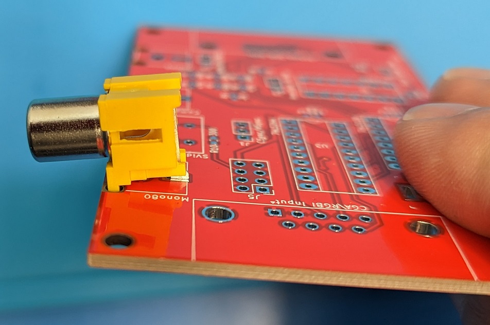
The RCA Jacks fit their footprint perfectly minus a bit of an issue with the back pin. The back pin is a little tight with the specific jacks I am using, which are made to the the correct footprint. I initially thought that they wouldn’t fit, so below you see I filed down the back pin a little to make it easier. But with working on it further, I found they do fit, it is just a little tight depending how you align the pin installing it. So you can either get them to fit, or to make it easier you can grind/file off that little bit of the pin.
With a quick touch up using the Dremel I made the Yellow jack fit nicely. I filed that little upper lip off. The jack doesn’t “have” to be filed down, but it might be a bit tight or if your jacks are a little different it they may require it.
I am making up two of the boards. The first one to replace my original adapter for the Commodore 128. That one will reuse the short Commodore AV Port DIN Cable and the short DB9 Cable from the original. The other board I am building up as a CGA adapter board, I am leaving off the Commodore AV Port parts (mostly) and adding the Barrel Jack for the 5V DC input. I don’t currently have any computers that use CGA, but I figured I have five boards and plenty of parts to put one together
.
The original adapter and the two new ones I am looking to assemble.
I salvaged the cables, ICs and one of the sockets from the original unit as I am scrapping it. I wouldn’t have messed with the IC Socket except I was practicing with my desoldering gun. It turns out I only ordered one VGA port, so I had to salvage one from an old monitor switcher board I have. I managed to get it off, and it is the same footprint as the new one. It wasn’t too easy, but went fine.
The two boards after soldering.
They turned out looking pretty good overall. The right board is the CGA board without the Commodore AV functions. It will take IBM CGA and a 5Volt DC Power adapter to make it into an Analog RGB signal with the CGA Brown Fix applied. That can go into a GBS Board, GBS Control modded board or something like a SCART to HDMI board. The primary limitation with the SCART to HDMI board (other than a lot of latency) is there would be no Audio on the SCART as CGA doesn’t have audio on the cable (for the Commodore 128 the Audio comes from the Commodore AV DIN Port). That and you need a Analog RGB to SCART cable, which my cable is a bit custom, see my cable pint out in the “original” project post from 2019.
The board is a perfect fit into the project box that I used for the original adapter. The openings are all different though, and you can not drop it in once the ports are soldered on. I guess you could “slot” in all the openings, but that leaves gaps from the top, which I don’t like. I plan to design a 3d printable case for the board. That is a part of the project that will have to wait until next weekend and likely longer though. I want to make it so it had all the required openings and is a simple split case that will fully enclose the board.
I do have to check that the boards are wired properly, mostly the Commodore 128 version with the cables. Then I will test the boards and see how it works. I will make the required corrections and changes on the pcb design and upload them to Github.
Above are some pictures of the testing. The Monochrome 80 Column pass through doesn’t work. I wasn’t thinking and passed it through the 74LS244 buffer, which it doesn’t work that way. The v1.3 board design no longer passes the Monochrome 80 Column video through the 74LS244. That is corrected on the v1.3 design I released on Github.
The rest of it works. RGBI works, 40 Column Commodore Composite pass through works. The 40 Column Commodore S-Video pass through and Audio via the RCA Port work properly. My Commodore 128 is being odd, I am not sure if it has something wrong with it, so it has limited my testing options. I did work on the C128 awhile ago, and it all appeared to be working except the cartridge port was being problematic. I haven’t been able to get it to work fully with the pi1541, although the 80column programs I tested are working through the pi1541. It may be because the pi1541 I am using is the 3A+, and the sdcard is setup for my 3B+ instead. I think there is a setting change required for timings.
The first image is through the GBS Control, with scan lines enabled. I have another post where I build GBS Control if you want to see that. The next being the adapter board connected up to the GBS Control. The second row starts with the SCART Converter to HDMI on the same color test. It is brighter due to no scan lines. Then the SCART Adapter connected up. The last picture was me testing an 80 column game using the GBS Control. I did find that the SCART Converter was not being stable when in a game though, it was flickering and blinking in and out. The GBS Control was stable on the same games. I am wondering if it is something with the sync signal. The one IC is a HC chip, which should be either an LS or HTC, that may be doing something to the signal that the SCART Adapter doesn’t like. I have another IC on the way. I’ll be testing the SCART to HDMI again when that comes in. I also did the bodge for the 80 Column Monochrome output and I will be testing that when I put the boards into their new 3d printed cases.
This is a follow up to an older project I did. The RGBI (RGB Digital) to RGBA (RGB Analog) for the Commodore 128 80 Column Video. Commodore’s RGBI is essentially the same as CGA so the adapter works on either. I made my prototype adapter back in 2019. I wanted a project to work on and wanted to work with KiCad to see how that went.
I had started making a PCB Design in Eagle back in 2019, but I never finished it. I didn’t want to keep using Eagle so I stopped working on it.
This project is the RGBI to RGBA project packaged into a custom PCB Design and with a few additions. Such as a dedicated 5V DC Power Jack for when using it with an IBM Based pc for CGA.
It still has all the Commodore functions and more passthrough functions now for the Commodore 128. The Commodore specific parts could be skipped though.
Below are some pictures of the PCB Design work in progress.
3/4/23 the finished v1.3. Is ready to download.
The board is sized to fit into the same case I used for the prototype. The problem with that is you can not get it into the case with the DB ports soldered on. I still laid it out for that size and the mounting holes to match that case. I have a couple of them yet. I think it would probably be better to design a 3d printed case. I can make it split at the place I need to get it in and out easily that way.
The board layout is basically a DB9 port on the left side for the RGBI/CGA input. Along the top the first port is for a single RCA Port for 80 Column Monochrome output from the Commodore 128’s RGBI Port. It is there, so I figured it is easy to include. You don’t need an “adapter” to use the Monochrome output, it is just Pin7 on the RGBI DB9 port on the back of the C128, I am passing it through the 74LS244 buffer though. The next footprint is a SVideo Port for from the Commodore 40 Column from the AV Port, including a 300 Ohm resistor on the Chroma line. The next port along the top is for another RCA Port and it is the Commodore 40 Column Composite Video from the AV Port. The last port along the top is a third RCA Port which is the Audio Output from the Commodore AV Port. There along the right side is the 15 Pin RGB Analog Output. The bottom left has the 5V DC Barrel Jack footprint (Center Positive). The Header pins are the C64 AV Port, it is oversized as I want to make it “keyed” with a missing pin and a plugged hole in the connector. The CSync/HSync is to set the Sync output for the normal HSync pin on the VGA port to either be Combined Sync (CSync) or to just pass through the HSync normally. The Audio header is a jumper to either output the Audio to the RCA Port above it when in the Left side or to output it on the VGA port on Pin10 for when I use it with the SCART to HDMI Converter box. InvertSync is another jumper to Invert the CSync/HSync line if needed. Finally the SCART Blanking is a jumper to enable sending VCC/5V to Pin9 on the VGA Port again this is for when I use the adapter with the SCART to HDMI Converter box, this enables the SCART RGB Detection on SCART Pin 16.
I think it is a reasonably sized board. If it was to be used for CGA with an IBM Computer then you can install the Power Jack, and omit the 3 RCA Ports, the Mini Din Svideo Port and the 10 Pin Header for the Commodore AV Port. If it is going to be used for a Commodore 128 RGBI, just build the whole thing minus the Power Jack. I think the only thing with the power Jack is that plugging it in while having the Commodore AV Port connected could end up very bad. I might think about that a bit more if the 3pin Barrel jack could be setup to bypass the AV Port power or something like that.
I did go with through hole for the ICs, headers and ports. I was thinking of going with dual footprints for the Resistors and Capacitors to allow either through hole or surface mount parts. The Surface Mount capacitors and Resistors are 0603 Imperial size parts. I have all the ICs already in DIP/DIL, and I want them in sockets for easy replacement if required.
I had to make the footprints for the RCA Jacks, and the SVideo Jack. The RCA Jacks should have square holes on the front corners. I couldn’t see how to make such cutouts. I figure that I may just have to shave the plastic a bit on the RCA Jacks.
The board as well as the original prototype build can do a combination of outputs depending on your needs.
The board in the fully configured mode outputs RGBS, Red, Green, Blue and Sync (CSync or Combined Sync) with custom Audio and SCART Blanking voltage on the HD15 port. This is what you use for a SCART Input. With the Audio to the RCA Port and the SCART Blanking disabled (may or may not be an issue if it is enabled) the GBS Control also takes RGBS input. The GBS Control might get confused due to VSync being included too on the HD15 all the time. With the SCART Cable the VSync pin is just not wired to anything.
If it is set to HSync with the jumper then it outputs RGBHV: Red, Green, Blue, HSync, and VSync. VSync is always on the HD15 port. The GBS Control takes RGBHV, and that is the setup I use with it.
It will also do RGBS with an Inverted Sync with the other jumper. I think did that variation because of something to do with the GBS boards at the time. I don’t remember what it was about though for sure.
The other two jumpers are specific for doing the RGBS with SCART, that puts Red, Green, Blue, Sync, Audio and 5V on the 15 Pin output. It is how I used this adapter until I build a GBS Control to go with it. The GBS boards weren’t as good for this use until the GBS Control project came out.
When using the adapter in RGBHV mode the 74LS86 is not required. The 74LS86 is just used to make the CSync by combining the HSync and VSync. It is also used to do the Inverted CSync if that is enabled (which it would also Invert the HSync technically if it was enabled while the other jumper was in the HSync position). If you look at the schematic you will see it is just bypassed. The 74LS244 is a buffer to protect the Computer video output. The 74LS138 handles the CGA Brown Fix.
I have received the parts I had on order and checked all the footprints. There was an issue with the DB9 port footprint that I had to fix. I also had a few adjustments to make to the Mini Din 4 for the SVideo port. I made changes for footprint corrections and some adjustments to labeling then put in an order for the v1.2 PCBs. I am going to build one to replace the one I made in 2019 for my Commodore 128 RGBI, as I want SVideo. I plan to scrap the prototype, reusing the short DB9 cable and the short Commodore AV Din cable I made for it. I also plan to build up a second one for IBM CGA without the Commodore AV Port related components. If the board tests out, I will post the KiCad project files and Gerber files on Github. Once I have the boards built up, I intend to design a case that can be 3d printed.
Update: 3/4/23 v1.3 I am correcting the schematic, the original one had the 80 Column Monochrome Video from the Commodore 128 RGBI port going through the 74LS244, and it shouldn’t be. I am also adding R11 as an option for a “Resistive Ground (RG)” on the Shell/Shield of the 15pin output port, it probably should have a 100 Ohm resistor between ground to help prevent potential Ground Loop issues. To prevent ground loops with the cable shield is generally recommended to only be “grounded” on one end, so you can put in the optional R11 or omit it. All of the other connectors have their shield to GND/Ground.
I have been wanting to get a working display for the Commodore 128 80 Column mode. Looking into it, certainly get an old compatible CRT Monitor, either a Commodore RGBI monitor or apparently a CGA monitor potentially. Well they are old and they are expensive, and quite expensive to ship. There a couple more modern LCDs, including some NEC Multisync 70 series monitors. They are apparently around, but they are old and somewhat expensive too. If I get a display I would rather have confidence that it will last for a fair while. That and I am pretty cheap I guess.
I looked at options, the Monochrome Composite 80 Column mode is easy. Just make up a cable with the DB9 and a regular RCA plug on the other end. I want color though.
There are some CGA(RGBI) to VGA converters that people make to sell. They convert the Digital CGA signal to an Analog RGB signal, that is close to VGA. The frequency is at the CGA 15khz though instead of 31khz like VGA though. So most monitors don’t accept the 15khz signals (NEC Multisync 70 series is one of the few again, and the 60 series that I have doesn’t). Then you need a second unit that then takes that 15khz to a 31khz VGA signal.
I found a circuit design for a CGA/RGBI to Analog VGA. This is the first part, and you need a secondary converter to take the 15khz signal to the standard VGA 31khz. The GBS-8200 is a popular solution to take the signal to 15khz. I found another solution, which is a SCART to HDMI converter that Adrian Black posted about on his Youtube channel. I picked one up, an a donor cable to make up a proper cable for it.
I took the RGBI converter diagram and came up with a bit of a hybrid of it. I had tried an earlier wiring up to see if my Multisync 60 series monitor worked, it didn’t. So I am making up up circuit I found. There was a report by another site that said they didn’t like that circuit, and preferred another circuit for the process.
The draw back of these RGBI converters is that while they are full 16color output, they output Dark Yellow in place of Brown. It is not a fault of the circuit, it is because that is how CGA/RGBI worked, the Monitors actually handled the color replacement. To do the Dark Yellow to Brown replacement requires including the 74LS138N ic. When it gets the “Dark Yellow” signal, it injects just a little bit into the “Green” pushing the visual output from Dark Yellow to Brown through R1 below.
Update 2/5/23: Today I was looking to revise this project to a PCB Design. In looking at, it I and thought the Sync Invert was incorrect on the schematic. I was wrong, it was correct so I have switched the schematic back to the original from 2019. I have no promise I will complete a PCB design, but if I do I will be posting it up on Github or another site. I am thinking of making the pcb to fit into the same case I used for the prototype if possible. To make it more useful for IBM CGA I plan to put a power jack on it, the Commodore AV Port will be a pin header row or something, so it will be optional. There will be the optional Audio Jack coming from the Commodore AV Port, as well as an option for the Monochrome 80 Column Composite output (because I can), Commodore 40 Column Composite as well as Commodore 40 Column SVideo output. I am making the PCB Design in KiCad at this point. I want to see how that works. I had used Eagle back at the time of making this project initially. I have recently used EasyEDA as part of the Super Game Boy project, as Joe had build it in there. I wanted to see how KiCad compares. The schematic is nearly finished in KiCad, but the one in Eagle as seen below looks “neater”. I am finding some issues with KiCad not having footprints I would like to be ready to use, but we will see once I start having to work them out and find parts.
Progress on the 2023 PCB Design. See my other posts on the progress there. V1.3 files are now released, see “Part 4” post for the links.
Here are some pictures of the unit built up on some protoboard and reusing a section of board with a HD15 VGA connector on it. There are a couple of things I will be doing with the board, first I will be installing a 150 Ohm resistor on the board (R9). Currently in the second picture you can see an old 150 Ohm resistor in there for testing. I was making sure that 150 Ohms wasn’t too much and that it brings the current usage down to what I consider should be a safer level. Initially I had been using a higher value resistor and the circuit wouldn’t work. The SCART box needs enough voltage on Pin16 “Blanking” which switches it over from Composite Video to RGB Video mode. With too low a resistor I wasn’t happy with the current draw. I am going to be powering this board from the Commodore 128’s AV Port. I didn’t want to risk damaging the computer by pulling to much power through the port. With the 150 Ohm it had lowered it to a better level. The other changes I will be making also involve the AV Port connector. I want to be able to connect up for both 80 and 40 Column video modes, with the AV Port plugged into the box for power, I can’t get to the 40 Column signals. I am going to add another RCA jack for the Composite Video, I will also add a SVideo port somehow later on, so that will be an option for 40 Column mode. The a RCA port was the Audio out coming in from the AV Port originally when the first pictures were taken (in the end I moved the Audio to the side, and made that port 40 Column Composite Video). The Audio also goes into the “vga” jack and is sent to the SCART converter to go into the HDMI signal from it. I could have hard wired in the SCART Cable instead of including the VGA port. I wanted to give myself other options with the box though. That is also why there are some jumpers on the schematic. They are there on the board, but they are not easy to see as they are a bit under the wires in the pictures below. The jumpers can allow to switch from Combined Sync mode (CSync), to the VGA Split Sync (HSync & VSync). The second Jumper is the Inverter jumper for CSync/HSync line, with it one way the CSync is inverted, with it the other way it is not inverted. This gives options to potentially connect to other devices, like the GBS8200, maybe some Multi Sync VGA monitor if I come across one. The only concern I have with either of them, is that I am sending Audio to the VGA port to Pin 4. If the Monitor or the GBS board do anything with Pin4 they could damage the SID or be damaged themselves. The other alteration on the VGA pin out is Pin 9 has the “Blanking” voltage wired into it, old VGA cards (very old I guess) sometimes had a 5Volt output on that pin, so as I am feeding it with something under 5Volts it shouldn’t do anything, but that doesn’t mean something won’t be wired to it. I have seen diagrams of people thinking Pin 9 on the VGA port should be Grounded, which that would be bad.. certainly it wouldn’t be a good thing to do.
So after a lot of checking of my wiring, I finally connected it up to the Commodore 128, and well it worked. That was great because I couldn’t get it to work 100% on the breadboard. I though the issue might be the variation of the XOR Gate IC I was using, so I had ordered in some replacements, so it was either that or all of the slop of the breadboard wiring. There is that “Saturn’s Rings” looking interference there going across centered around the Light Blue line. That was a visible thing on the display. I didn’t have that specific issue in the breadboard circuit. The point to point wiring isn’t the best either, so maybe that has something to do with it. I have yet to try it on another monitor though. Still I am pretty happy with it, and soon I will be able to close the box up and make use of the 80 Column mode when I want to. The color correction on the Brown seems to be working, the text at the top is in “brown”. At the least I can say it looks closer to Brown than Dark Yellow to me. The other colors look reasonable to me as well.
Success.
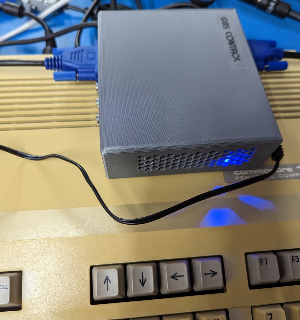
Below here is the SCART to HDMI Converter I am using. I found it on a video by Adrian Black where he was recommending this model specifically over the other similar priced models. He said that Heatsinks needed applied to the two chips inside though.
Below you can see the two heatsinks I installed. I hope they are enough, the little one in the lower right is fine, but the main chip heatsink is smaller than the one Adrian was using. I don’t know how hot these get with use. If they “sort of work” without them, I would hope that they will be just fine with these. They are the type that come with some 3m tape applied.
Two Heatsinks Installed for reliably.
Above I have put together a diagram of the Output of the circuit I built and how it is wired to the VGA port and then how that wires over to the SCART Cable. For a GBS8200 or proper Multi Sync VGA monitor you would just use a regular VGA Cable. I would feel better if you used a minimal VGA cable, which is R,G,B, Ground, C Sync/H Sync and V Sync. I find that the thin modern VGA cables now only have those wires in them. I have had older ones that were about as small but did have all of the wires in them. I am putting in a jumper to disconnect the Audio from the VGA port for safety. When the jumper is moved to the other position the audio then goes to the RCA port on the side (the Red one not the Yellow one).
Here is the Analog RGB side. The RCA port there is now wired to the Commodore AV Port Composite Video (40 column output). I painted it yellow to reflect what it is.Here is a top view once it was finished. The Additional RCA on the side is now wired to the Audio Out from the SID via the Commodore AV port and is Red to reflect it is an Audio port. Below you will see an additional “jumper” that is not on the schematic labeled “<Audio” that is a 2 position jumper that either passes the Audio to the “VGA” port or to the Red RCA Port depending on the position it is set to.Above I put on text for the 4 jumper locations and functions. SCART blanking is connected or disonnected, Audio is to the VGA Pin4 or to the Side RCA. Then CSync Inverter or non inverting. Finally CSync or HSync (such as if I had a compatible MultiSync Vga Monitor)
I certainly look forward to using this setup for my Commodore 128. I added the label below, it is printed on an inkjet printer with standard paper. I then used some tape to mask off the top of the box, and sprayed it with Locktite Spray Adhesive 200 Middleweight bonding spray. I let it slightly dry before putting the paper inplace so that it would not bleed into the paper. It is sticking perfectly, I guess I will see how long it holds up. I may have put some clear packing tape over it before cutting it out, but I didn’t have any. I have used the process for some cartridge labels as well.
Nothing above is exactly what I ended up with, but that is what I based my converter off of. I used H2Obesssion’s CSync and SCART info, and then the other for the Digital to Analog and Brown fix. I would really have liked H2Obession’s “Ultimate” circuit to have worked out. There were reasons it did not work in my case, mostly I think it was the SCART Blanking. If I make another, I was thinking of trying it again.
The unit does work for me, it may not startup the Sync signal quickly enough and I have to reset the Commodore 128 to get the display to show.
The design can be adapted for IBM CGA use. The only difference there is the source of the 5Volt power as there is no Commodore AV port to supply it. Certainly a DC power jack could be added instead for a 5Volt DC power input.
I also have a Commodore 128 and original power supply. The supply was in working order. As console5.com had a capacitor kit for it, I figured I would take care of replacing the Capacitors in it. The main trick is that my supply’s model number doesn’t match the contents.
The model on this drive seems to indicate the internal supply should be 310416-05 but the internal is actually a Mitsumi 252449-01. I checked the supply before so I knew which kit I needed.
The supply came with 4 plugs in the screw holes in the bottom. They aren’t always the easiest to get out. One was already missing and the next two came out easily. The final one I ended up drilling a small hole in it to pull it out. I wasn’t worried about putting them back in.
The supply with the original Capacitors.The new Capacitors.
This a rather simple job. There are only two capacitors in this model of supply. The replacement ones are a good bit shorter, and have a very slightly smaller diameter. They are good quality and 105 Degree rated, as well as low ESR types for proper operation in this switching power supply.
Here you can see all of the flux still over the bottom of the board from the factory.Here is the board after I switched the Capacitors and cleaned the flux from it.
Here is the board after installing the capacitors. I also touched up a few other connections. I cleaned the old flux from the board as well, it looks much better cleaned up.
Here is the completed supply reinstalled in the case with the old capacitors beside it. I tested them and they do appear to likely be fine, but I don’t have way to test them for power leakage that happens with capacitors as they age. I trust the supply better with the new capacitors in it and expect the supply will be more reliable long term.