You are using an out of date browser. It may not display this or other websites correctly.
You should upgrade or use an alternative browser.
You should upgrade or use an alternative browser.
U47 Clone with 5693 tube
- Thread starter Enchilada
- Start date


Help Support GroupDIY Audio Forum:
This site may earn a commission from merchant affiliate
links, including eBay, Amazon, and others.
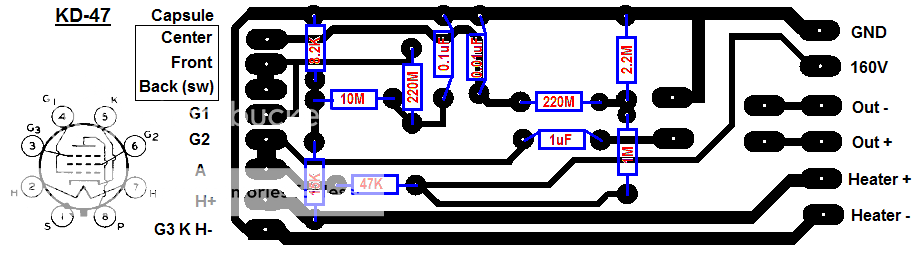
If you just want random ideas: I would not have the capsule to G1 or 220Meg system on the PCB at all. Modern PCB stuff is not as leaky/noisy as the old paperboard, but still why risk moisture troubles? And the excess length over to the 220Meg. Air-wire it. Capsule to tube socket G1, 220Meg on socket, lead the other end of 220Meg to bias on PCB.
That PCB could be a lot smaller, but I suppose it suits you. Also I have learned not to be too clever or too small with first attempts. Excess space can fit all kinds of bonus parts (fix-ups).
Like: is that space for the 1uFd big enough for a 200V part? Or for some papyrus and virgin-oil exotic cap? I'd have a row of holes to the left so "any" size cap would fit without much cussing, kinking, or flopping.
BTW: 6J7 is the same tube, except with top-cap, which avoids even socket leakage. 6J7 is a very sweet audio tube. There are no cheap/modern or re-marked 6J7, totally golden-age. Prices are still good. I've never seen a bad one. Ken-Rad is a reliable brand, but I suspect most market-brands are Ken-Rad or Cummingham and good. My only wonder is microphonics: 6J7 are very tame in a rack or on a shelf, but I never used one close to a high-level source. I suspect it is no worse than 6SJ7 or that RedBall marking.
Yep, this is definitely my first crack at a PCB and I'm very much still learning how tube mics work and electronics in general. I don't mind that it's a little bigger than it needs to be. Like you said, it might make it easier to edit later.
I was originally looking too see if this PCB design is correct and that I haven't made any errors but those are some great ideas that I will definitely take on board. Especially the row of holes for the 1uF cap, that's why I left all of that space to the left and below it it but I was just planning to bend the wires. Your idea makes much more sense.
Thanks!
One more thing to note.
I decided to go with 160V because if others want to build a U47 clone with this PCB they are free to do so and could easily base the PSU on the Gyraf G7. However, now I'm looking at the PCB with fresh eyes, I'm thinking I should increase the value of that 47K resistor.
gemini86
Well-known member
6sj7 is a good microphone tube, but finding a quite one isn't always easy. Buy a bunch, try them out.
gemini86 said:6sj7 is a good microphone tube, but finding a quite one isn't always easy. Buy a bunch, try them out.
Thanks for the tip. I've got access to about 100 of them so I'll be able to weed out the bad ones
")
PRR said:BTW: 6J7 is the same tube, except with top-cap, which avoids even socket leakage. 6J7 is a very sweet audio tube.
Thanks, I'll see if I can get my hands on one and give it a go also. The best fun with the 6SJ7 will be getting it to fit because they're HUGE!!!
I have built a couple of mics with 6SJ7.
With a big tube & socket wired off the board, and a transformer wired off the board, and some of the high impedance parts wired off the board... do you you really need to make a printed circuit board for this one?
The U47, and other mics of that era, used small strips of tag or turret board for the circuit. That would be a good way to do this one. Easier to fix errors too.
Good luck!
I agree but I thought that perhaps this could be a good project for beginners who were after a U47 clone with no interest in learning how to read a schematic. It would make it easier to fit a tube and transformer in the the body though.
Thanks for the encouragement
I ordered some parts from RS online today. Can't wait to get building ;D.
Thanks for the encouragement
I ordered some parts from RS online today. Can't wait to get building ;D.
Hey guys,
Parts all received, PCB redesigned and halved in size, PCB populated and soldered ;D.
But I'm now a bit stumped with my U47 clone. Here's the original U47 schematic:
http://www.cntube.com/UploadFile/200812141157189934.gif
Now while I can see how the voltage at the anode is +34V after passing 105V through a 30Kohm and 100Kohm resistor. However, I don't understand how you would find +63V at the capsule centre. Surely after sending 105V through a 2Mohm and then a 100Mohm resistor the voltage would be next to nothing (this is what has happened in my attempt at a U47). I really fail to see what I am missing ???.
Perhaps I have wired the capsule incorrectly. At present I have wired it in cardioid mode only for simplicity. To me it looks like the case of the switch has been grounded in the schematic but I still cannot see how you might find +63V at the capsule centre.
Can anyone explain this to me? It would be much appreciated.
63V is the result of the 2M / 3 M divider of 105V. The 100M is in series with the infinite DC load of the filtering cap and the capsule capacitance, hence isn't reduced. But you won't measure this voltage post the 100M resistor with a normal multimeter
Ahh good. Although I understand voltage dividers with only resistors for some reason I didn't even see it there :. I learnt about dividers when I built my G7. Looking at it now though I feel kind of silly that I didn't see it. So does the 100Mohm resistor and the 0.01uF cap act as a low pass filter (just so it's clear to me).
When I built my mic, I went with 200Mohm because I didn't have any 220Mohm. The divider is this mic I'm building is working as it should, measuring just under 60V before the 200Mohm resistor. I've never fully understood low pass filters though and I hope the 200Mohm and 0.01uF are correct values. Perhaps I should use 100Mohm instead.
. I learnt about dividers when I built my G7. Looking at it now though I feel kind of silly that I didn't see it. So does the 100Mohm resistor and the 0.01uF cap act as a low pass filter (just so it's clear to me).When I built my mic, I went with 200Mohm because I didn't have any 220Mohm. The divider is this mic I'm building is working as it should, measuring just under 60V before the 200Mohm resistor. I've never fully understood low pass filters though and I hope the 200Mohm and 0.01uF are correct values. Perhaps I should use 100Mohm instead.
BTW, the U47 is working well although the tube is amazingly microphonic. Even tapping the mic cable when it's in a shock mount gives a high pitched "ding". I'll clearly need to try another one. I would love to try a glass 6SJ7 but there isn't enough room in the donor mic I used.
I'll get in the studio and record a sound sample tomorrow
I'll get in the studio and record a sound sample tomorrow
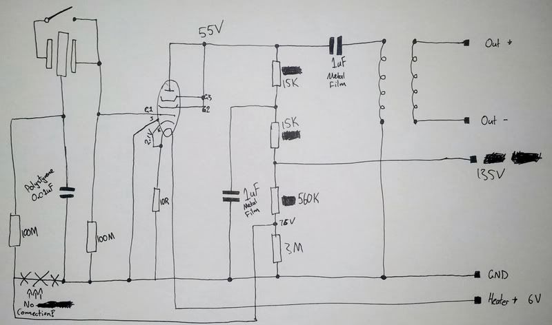
Tried the glass 6SJ7 and although it's not anywhere near as microphonic as the 5693, it doesn't really sound any different. I've been playing around with the circuit and although it sounds better, it's still lacking in bottom end and there's still a fair 1kHz hump.
Here's the circuit I have thus far:
[Edit: the divider for the capsule voltage is actually 560K-2.2M]
Here's the circuit I have thus far:
[Edit: the divider for the capsule voltage is actually 560K-2.2M]
moamps
Well-known member
Hi,
according to your schematic, heater and anode voltages,
the tube is underheated (4V) and overloaded (15K-1uF-15K). IMO.
Also, the capsule bias voltage is too high (over 110V using divider 560K-3M), what can
cause poor LF response.
Regards,
Milan
according to your schematic, heater and anode voltages,
the tube is underheated (4V) and overloaded (15K-1uF-15K). IMO.
Also, the capsule bias voltage is too high (over 110V using divider 560K-3M), what can
cause poor LF response.
Regards,
Milan
Perhaps my power supply isn't too crash hot. My calculator was telling me voltages should be one thing but the numbers on the schematic are what my multimeter tells me voltages are. I thought I was going mad. Previously I used 1M-2.2M as a divider for the capsule and it was reading only around 25V-30V at the divider, not at the capsule.
I also previously used the same 30K-1uF-100K from the U47 although this resulted in only 25V at the anode according to my multi.
Regarding the heater, I must be looking it it incorrectly.I thought the resistance of the heater combined with the 10R resistor would act as a divider for the cathode voltage but the heater voltage would remain at 6V. Can someone please correct me if my assumption here is incorrect.
Thanks heaps for the feedback, I think maybe I should rebuild the power supply as you've validated for me that these voltages should be much higher than they're reading.
My calculator was telling me voltages should be one thing but the numbers on the schematic are what my multimeter tells me voltages are.
The problem here is that your multimeter (probably) has an input impedance of 40 megaohms, but you are trying to measure circuits that are up to 100 megaohms. Your meter makes a voltage divider with the circuit, and so your readings are lower than they should be.
As moamps says, 15K looks too low for the plate resistor - Why not start with 100K like the U47 schematic, and tweak from there. Your capsule is probably collapsing under the high voltage, so go back to about 60 V on the capsule to be safe.
For the heater, you want a voltage drop of 6V (or a little less) across the tube filament. So if the left hand leg is going to be at 2.1V, then you need to up the supply at the right had to about 8V. If your supply won't go that high then forget the fixed bias, and just use a cathode resistor.
Stewart
yes, i would run the heater of the 6sj7 off the 6 volt supply, and use a cathode resistor, you will probably get less hum from not having any ripple off the heater supply modulating the cathode, you can cancel it out, but those tricks are only done when they have to be,
do you have a scope? what kind? scopes will measure dc but if the input Z is just as low as the voltmeter you are using, then it will not help. but a fet input will have infinite Z, in theory that is, an old vac scope will have the input Z of the type of tube it has, what is input Z of 6dj8? have to look it up,
if it is a metal tube, be careful with the shield wiring, sometimes they have a pin for the shield, sometimes they hook it up internally to one of the elements, the cathode i presume,
the vf 14 is a very different tube from the 6sj7 so you might have to change some things to dial in the sound and noise,
I might go back to 100K-1uF-30K for now. Regarding the cathode resistor, I'm feeling rather uneducated here. I thought the resistor from K to ground was a cathode resistor. The only other way I can think of using a resistor here is to connect the left leg of the heater to a higher value cathode resistor, to the cathode and then to ground as opposed to using the resistor and the heater together as a divider. Or are you saying that I don't connect the cathode to the heater supply and just use a cathode resistor?
I was going to buy a scope but at present I don't have one. It is on my to buy list though.
The 5693 is a metal tube but the 6SJ7 is glass. I'm more focusing on the 5693 for now though. I don't believe the shield is connected to anything internally. Pin 1 is shield, I have it connected to ground. Should I connect it to the cathode?
Thanks heaps for all the help guys, this is all good learning for me.
I was going to buy a scope but at present I don't have one. It is on my to buy list though.
The 5693 is a metal tube but the 6SJ7 is glass. I'm more focusing on the 5693 for now though. I don't believe the shield is connected to anything internally. Pin 1 is shield, I have it connected to ground. Should I connect it to the cathode?
Thanks heaps for all the help guys, this is all good learning for me
.Or are you saying that I don't connect the cathode to the heater supply and just use a cathode resistor?
Yes, that is what I was trying to say!
Stewart
Similar threads
- Replies
- 25
- Views
- 2K
- Replies
- 4
- Views
- 494
- Replies
- 73
- Views
- 6K