Hi everybody!
Winter is coming (nearly), so I thought the time for a not requested entry here was mature again. Today, I will provide some updates about my simulation projects and I will analyze into more details the design of Peugeot 9X8 Hypercar front suspension. I recently realized, thanks also to new pictures and some discussions with some smart people, that a couple of points are not exactly how I described them in my latest post.
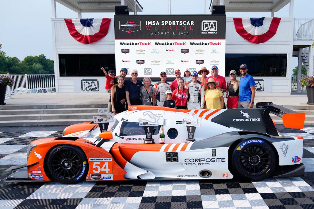
CORE Autosport is 2022 LMP3 IMSA Weather Tech Champion!
The last few months has been quite busy and, luckily, mainly with funny stuff.
CORE Autosport, the team directed by my dear friend Jeff Braun, who campaigned an LMP3 car in the IMSA Weather Tech Championship this year won its class, and it was really a joy to play a small part in this fantastic team’s success by helping a bit on the simulation side.
It was a very good season, with solid performances in every race, also thanks to a fantastic job on track side, both from a strategy and execution point of view.
CORE interpreted the spirit of a gentlemen class like LMP3 fully, with a crew composed by a very fast, professional driver (Colin Braun) and two bronze rated guys (Jon Bennet and George Kurtz). For the shorter races, Colin and Jon shared driving duties alone, while for longer races, like Sebring, Petit Le Mans or Daytona George was also in. Other teams had maybe a slight advantage with this respect, having crews often composed of young, silver rated drivers too.
We spent quite some time on the simulation side, trying to analyze upfront as many scenarios as possible to come prepared to races and the very few test days. We tried focusing on some specific metrics we isolated during the season; those helped to dial the car reasonably well before hitting the track at all and, in general, to hold it in a pretty small window, that we understood being what our drivers liked to perform at their best.
This has helped even more in occasions where bigger setup changes had to applied, for example because of specific tracks requirements or not foreseeable situations that came our way.
This project was really one of the best examples to show how, even with a simple, home made tool like mine, some good work can be done to make a racecar faster, more consistent and to exploit it better.
To me, this further confirmed how the way we use our tools is at least as important as how good the tools themselves are. In my limited experience what is crucial, beside the accuracy of the models (I talked about correlation already in my last entry here) are really the targets we set and the metrics we use to assess the results of every run.
Lap time, for example, is only seldom really important: it really provides useful insights when doing high level studies like sensitivity analysis (for example the effect of weight or engine power on performance or downforce/drag scans). When working on car’s setup, anyway, this is usually not the parameter you are most interested in. The car has to be good for the actual drivers, and the settings required to achieve this often do not coincide with what produce the best lap times in a simulation environment. There are so many parameters that cannot be controlled on track, or are unknown upfront, or cannot modeled easily; as a consequence, simulation becomes really helpful if we use it to analyze as many “what if” scenarios as possible.
To be brutally clear, CORE would have most probably won the championship also without my help, but I am happy I could also play with them a bit!
Peugeot 9X8 Front Suspension
In my last entry, I tried my best to analyze some pictures of Peugeot brand new Le Mans Hypercar (LMH) front suspension. I provided a brief analysis of how I thought the system would work.
Thanks to a conversation with a very clever guy, I understood that I missed a part of Peugeot architecture, something not easy to spot in any picture. Incidentally, the above mentioned guy, whose name is Ciro Tulin is building his own racecar using a Lotus Elise as a base and has planned to use a very similar layout for the front axle. He is a very smart person, with a background in Mathematics and Physics and talking with him I realized that Peugeot design is even more elegant than I thought and described last time.
To better analyze and show how it works, I built up a CAD model, that should be a decent representation of Peugeot front suspension, at least from a qualitative perspective; this assembly will help to describe how they achieve the decoupling of roll and heave control, with a very neat and compact design.
Let’s start from the beginning.
First of all, why decoupling roll and heave control could bring any benefit, in terms of performance?
When we consider cars where downforce is an important performance driver (and this is the case for LMHs, despite the significant drop the regulations imposed in terms of aerodynamics performance, compared to previous LMP1 cars), one critical point is controlling ride heights as good as possible. Ideally, you want to do that without compromising (too much) how the car handles on non-smooth surfaces, so without exchanging any elastic element with rock-stiff components.
One reason why controlling ride heights is so important is that, normally, by keeping the car very close to the ground, downforce is bigger and drag drops. Another important point is how the aerodynamic balance moves, when the car is subject to heave, pitch or any other motion (roll, for example). In general, you want to avoid that the center of pressure of the car moves out of control, causing instability or suboptimal handling, for example in braking and corner entry, where the front normally drops while the rear rises.
Without active suspensions or any other smart system, like the interconnection of front and rear axle or devices like inerters (all of this is forbidden by LM regulations), the only way to keep ride heights under control is too set stiff wheel rates (vertically).
If the car does not have a separation between roll and heave control, this would mean having a very stiff car not only in heave or pitch, but also in roll, and this could be undesired.
Since many years, even in lower classes a step forward in marrying those conflicting targets was achieved using third springs and dampers, in an attempt to give to teams the possibility to make heave stiffness higher, without necessarily influencing roll stiffness, by making the corner springs too stiff.
Anyway those systems still force the engineers to accept compromises, because if, for whatever reasons, they would decide to increase corner springs rates, this would still affect both roll and heave.
This issue does not exist with an architecture able to decouple completely roll and heave control, as the one Peugeot developed.
Another advantage of such an approach is that it would also allow control separately roll and vertical damping. This is maybe less critical, but could still offer interesting possibilities, above all when cars weight gets higher, as indeed happened with LMH vehicles compared to LMP1.
How much of an advantage could such an architecture brings in terms of final performance (lap times), compared to a more traditional approach?
I really don’t know. It is really difficult to estimate, as beside the architecture itself many other factors could play a role, like installation / execution quality, the final settings (stiffness and damping), etc.
Still, beside allowing to adjust roll and vertical stiffness and damping independently, such a design would open the door to a less compromised approach to a racecar mechanical setup, ensuring a much higher flexibility in adapting car’s behavior to driver needs and tracks requirements.
From Lawrence Butchter’s wonderful photos (linked in my last entry) it became clear Peugeot was trying to separate heave and roll control by grounding the torsions bars one against each other (instead of on the monocoque), thanks to a rod connecting left and right side.
There is anyway more than what I mentioned last time.
The proof my description was not complete was provided by pictures I got from Rodolfo de Vita, an engineer (and great photographer, I would add) that is (luckily for me!) also an endurance racing and racing cars fan.
One of his photographs is here below.
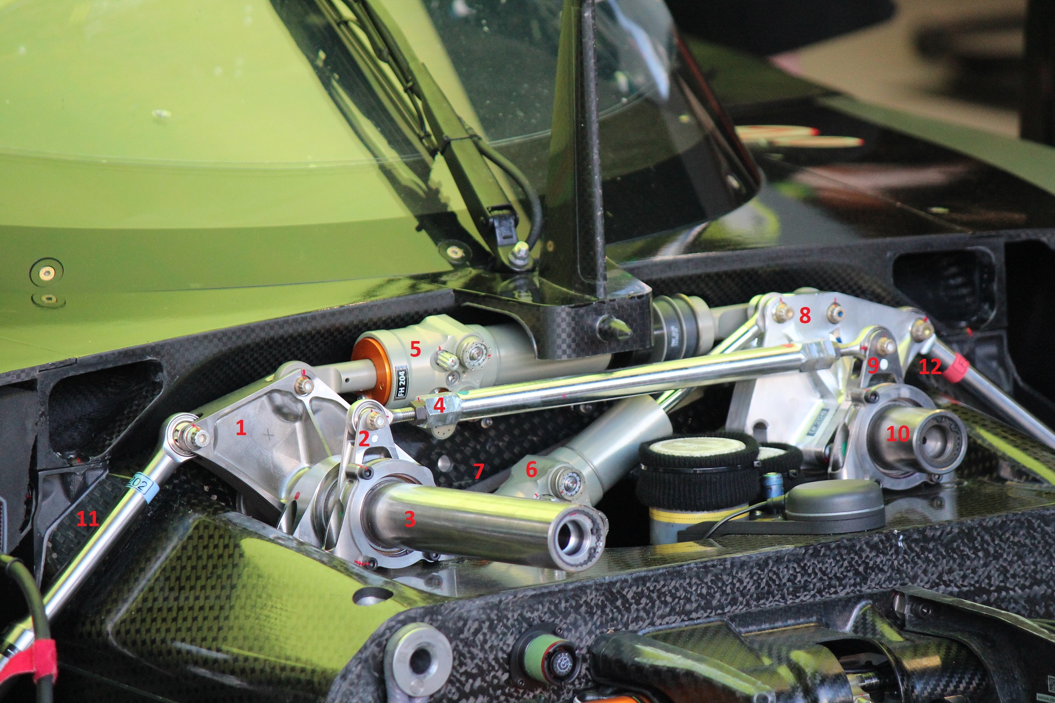
Let’s try to break down what we see and isolate all the visible components. Disclaimer: some of the components that are relevant for this analysis cannot be seen in this or any other picture I found. Ciro’s help in detecting them and understanding their role has been really precious with this respect.
The two main rockers are highlighted with the numbers 1 and 8 in the previous picture. They are activated by the two pushrods (n. 11 and 12).
The right main rocker (part n.1) is not connected (in any relevant way for this analysis) with the front right rocker (n.2). Both of them activate the right (long) torsion bar (part n.3). The back side of the right main rocker is not visible, but it includes also a bracket where a solid diagonal rod (part n.7, barely visible in the picture above) is attached.
Left and right main rocker offer a mounting point each for the heave damper (part n.5) and for the roll damper (part n.6). Roll damper attachment to the right rocker sits below into the monocoque and cannot be seen in any picture I found. On heave damper’s shaft some black bump stops are also visible: they often play a critical role in controlling ride heights in specific situations, for example under braking.
The left main rocker (part n.8) is solidly attached to the left front rocker (part n.9). Behind it there is another small rocker, similar to part n.2, that is attached to the diagonal link (part n.7). Both the left main rocker (n.8) and the previously mentioned, non visible rocker, activate the left torsion bar (n.10) that is shorter than the right one. Part n.9, being solidly attached to part n.10, is also a part of this interaction.
The horizontal rod (part n.4) connects the two sides and, in particular, is attached to the small front right rocker (part n.2) and to the small front left rocker (part n.9, solidly attached to part n.8).
As some of you probably spotted, there is no antiroll bar, as I wrongly supposed last time: roll and heave control is absolved by two torsion bars and two dampers.
As I describe in my last post, the two torsion bars are not grounded on the monocoque, but only against each other thanks to the horizontal and diagonal link (part n.4 and n.7) and the rockers to which the two rods are attached.
Looking at the following CAD pictures makes easier to understand how the whole system works.
As a general rule for the assembly we are going to look at, each color signalizes a different component, with the only exception of roll and heave dampers.
I think a further disclaimer is required here. The CAD design of the parts shown in the assembly below is meant to only help analyzing how the system may work and is not in anyway representative of how the real components should or actually look like. In other words, I know the parts I built are ugly and structurally pretty weak, but I don’t care. This is not their purpose here.
Also, the dimensions of each part and the pickup points position have been chosen arbitrarily and are not representative of what Peugeot may actually use in their cars.
The purpose here is only to try and understand how Peugeot concept works and how this would allow to separate roll and heave/pitch control.
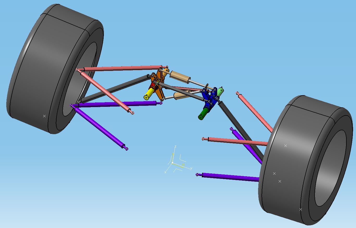
First of all, to allow this assembly to move, I broke down each torsion bars in two parts (light and dark green for the left one, yellow and light orange for the right one). They are constrained to each other like a hinge and by measuring the angle between each side “front and rear bar” we will be able to measure each torsion springs twist while the suspension moves.
Upper wishbones are in light pink, lower wishbones in violet while pushrods are pictured in dark grey.
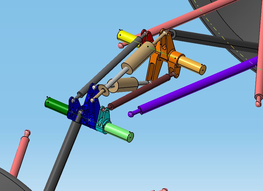
The right main rocker (rear) is orange, while the right front one is red. On the left side, the main rocker (front) is blue, while the rear one is cyan.
Besides the above mentioned parts, there is an horizontal rod (dark grey) connecting the front right rocker (red) and the front bracket of the left main one (blue) and a diagonal rod (brown) attached to the rear, lower bracket of the left main rocker (orange) and to the rear right rocker (cyan).
All of those rockers engage their relative torsions bars.
The assembly also includes an heave damper and a roll damper, that do not respect any specific color scheme.
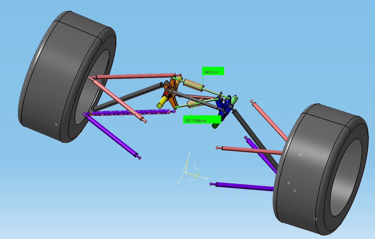
The following picture shows how long both roll and heave dampers are (ball joint to ball joint) in design position. The angles between each side torsion bar front and rear part (signalizing the twist that each bar is experiencing) are not shown, because they are both 0 degrees in design position.
Let’s analyze what happens in a pure heave motion.
Both wheels moves up with respect to the monocoque. What happens to the rest of the system is shown in the following two pictures relative to cases with respectively 10 and 20 mm wheel travel.
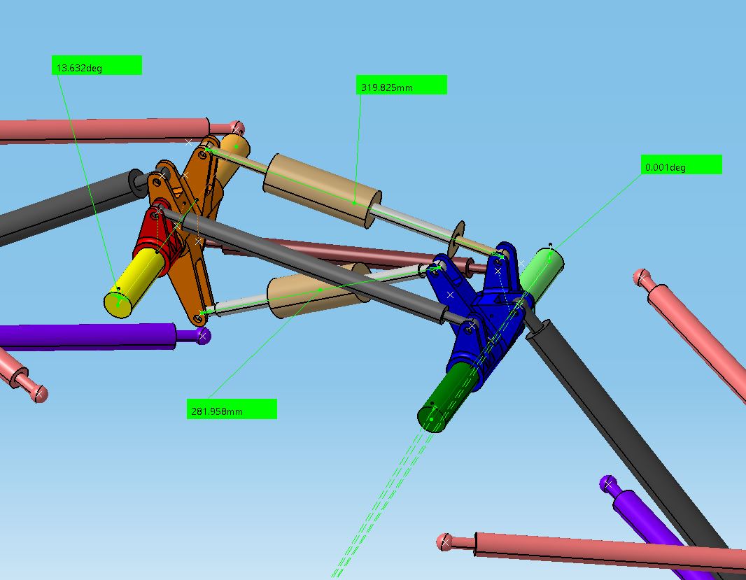
With this particular design, with a heave travel of 10 mm the left torsion bar experiences practically no twist, as the angle between “front and rear torsion bar” is 0.001 deg. Also the roll damper does not show any deflection, with its length staying as it was in design position. The right torsion bar, instead, experiences a twist of about 13.6 degrees while the heave damper travel is about 20.2mm.
A case with a heave motion of 20 mm is shown here below.
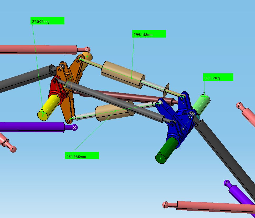
Once again, the roll damper does not move, while the twist experienced by the right torsion bar is negligible. On the other hand, the twist we see on the right torsion spring raises to about 27.8 degrees, while the heave damper further compresses, with a final travel of about 40.9 mm.
These first two analysis suggests that:
- the right torsion bar controls heave only, as does the heave damper
- the left torsion bar is not active at all in pure heave and the same is true for the roll damper
In other words, this seems to suggest this layout would at least allow to have only one torsion bar controlling vertical stiffness, which is the first step to get to the full decoupling described above.
What about roll?
Roll is a bit more complex to simulate with a pure, kinematic (CAD) model as the one we employ here. The reason for this is that in a real world, pure roll scenario we would not necessarily have the outer wheel moving up by the same amount the inner wheel drops, with respect to car’s body. Anyway, with the model and boundary conditions we can base this analysis on, this is the only possible method we can use to try and understand what happens in a roll-ish situation.
The following picture shows how the components move with a wheel travel of 5 mm in jounce on the right wheel and 5 mm in rebound on the left one.
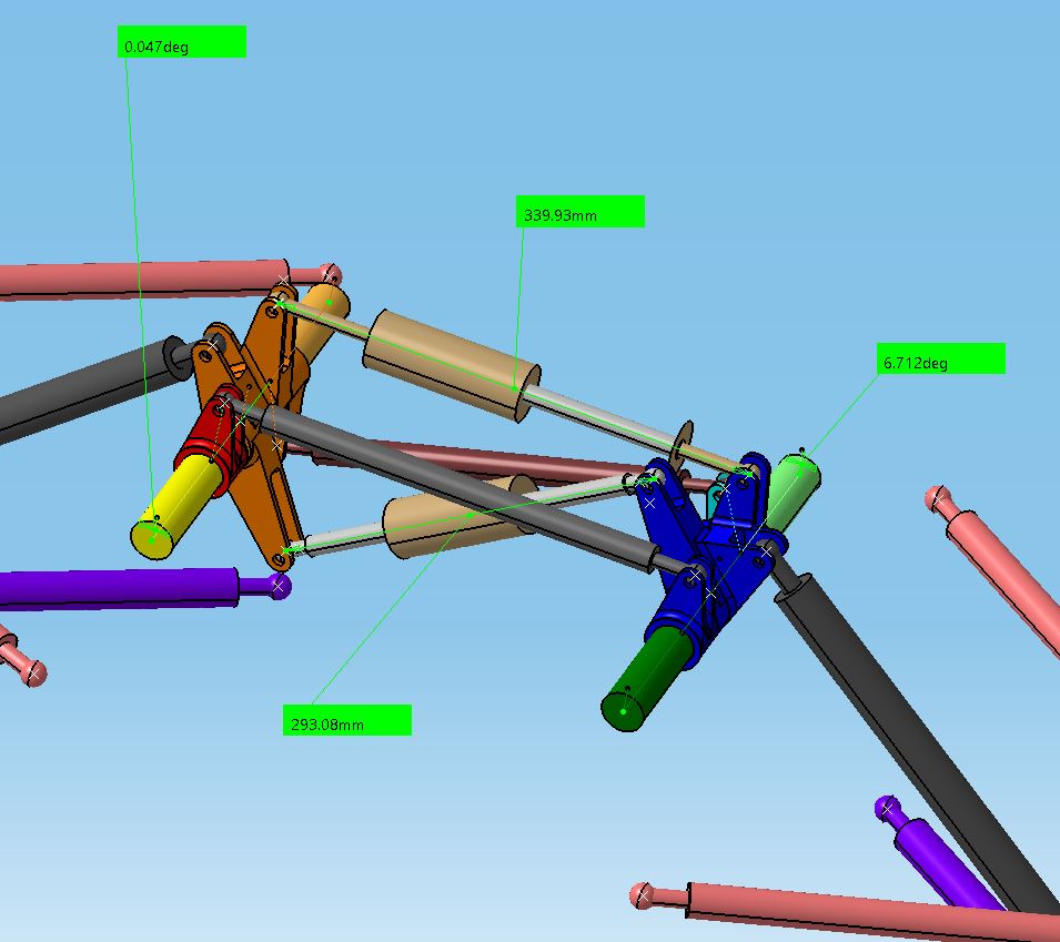
In this situation, we get a twist of the left torsion bar of about 6.7 degrees, while the right one barely moves (less than 0.05 degrees of twist). The heave damper also keep about the same length (it shortens by less than 0.1 mm) while the roll one gets about 11.1 mm longer.
What happens if we increase the roll angle by moving the left wheel up (with respect to car body) by a total of 10 mm and the left wheel down by the same amount?
This is shows in the following picture.
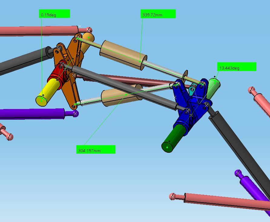
The right torsion bar shows a twist of 0.19 degrees. It is not zero, but it is really small compared to the left one, that is now twisted by about 13.4 degrees. We also have to keep in mind that, as I said at the beginning, an opposite wheel travel motion is not really a perfect representation of a pure roll scenario.
The heave damper keeps once again more or less its initial length (it shortens by less than 0.3 mm) while the roll one extends for a total travel of about 22.2 mm.
In summary, basing on the last two pictures we can see that:
- the left torsion bar controls roll only, as does the roll damper
- the right torsion bar is not active at all in roll and the same is true for the heave damper
This seems to confirm that what we found out by looking at the parallel wheel travel scenario was correct: this layout seems to be pretty effective in decoupling roll and vertical motion control.
What makes all of this even more interesting, is that this is achieved using only two dampers and two torsion bars, so with fewer components than in a traditional layout, with an advantage also in terms of package.
As far as I got, this setup is not fully new, as this could have been used also in Formula 1 before, but I could not find any picture to confirm this.
It is for sure an eye catcher and something interesting from an engineering perspective, integrated in a car that, as I said in my previous entry, is really breaking up with what we would define as traditional, running even more extreme solutions in other areas (see for example the absence of a rear wing).


All race car suspensions that I know of do a good job of decoupling roll and vertical motion with respect to springing but not damping. What this does not permit is different damper settings for right and left, nor does it allow for different damping in single wheel bump and roll. Most tracks have 360 degreed more turning in one direction than another and optimization may involve asymmetric damper settings. Also on the negative side is that crews would require additional training to work with it. Very clever, but will it find widespread adoption? Thanks for the analysis! Very generous of you to share!
By: John Evans on November 4, 2022
at 9:25 pm