
Frequently Asked Questions for Cisco Meraki Access Point Antennas
Cisco Meraki outdoor access points (including the MR74/76/84/86 and the newer CW9163E-MR) and certain indoor access points (MR42E, MR53E, MR46E) support the use of external antennas in order to focus their signal into a particular coverage pattern. This article covers frequently asked questions regarding the use and capabilities of antennas on MR and CW series Meraki access points.
Note you may expand or collapse the table of contents on the right of this page, which contains direct links to each specific question.
What are the Relevant Properties of Antennas?
The three primary properties of an antenna are the gain, the direction it radiates radio frequency (RF) energy, and the polarization of these signals.
The “gain” of an antenna is measured in decibels, which is a ratio between two power levels. In Wi-Fi we refer to a perfect, theoretical antenna as an “isotropic radiator,” which sends a uniform and equal amount of signal in all directions (a perfect sphere). Think of the sun as an isotropic radiator. In Wi-Fi terms, we use a unit called dBi, which stands for decibels with respect to a theoretically perfect isotropic radiator. We say that a perfect isotropic radiator has a gain of 0 dBi, meaning there is no gain when compared to itself.
All real antennas, even omnidirectional, have some amount of gain. That is, they focus the RF energy to some extent away from the perfect spherical pattern. This also gives a certain amount of “directionality” to the antenna, the second primary property mentioned above.
The dBi value expresses the amount of gain an antenna has with respect to 0 dBi. This can range from roughly 2.2 to 4 dBi for an omnidirectional dipole antenna, up to perhaps 7 or 8 dBi for patch antennas, and perhaps up to 15 dBi for more directional sector antennas. Note that the gain values are given per band, because gain is usually different for 2.4GHz vs. 5GHz signals.
The third property mentioned above, polarization, has to do with the direction of the electric field. An RF signal is an electromagnetic wave, which is the motion (oscillation) of electric and magnetic fields traveling through air or space. It is a “transverse wave,” meaning that the electric (E-plane) and magnetic (H-plane) fields are at right angles to one another and propagate perpendicular to the direction of travel. Ideally, the polarization of transmitting and receiving antennas matches one another to maximize received signal strength. This is typically more important outdoors for longer-range wireless mesh or bridge connections. Meraki outdoor patch and sector antennas are designed with both vertical and horizontal antenna elements inside. Please refer to the data sheets for the polarization, gain, beamwidth and coverage pattern information.
What is the Difference between Antenna Types?
Cisco Meraki sells three types of antennas: Omni, Patch, and Sector antennas. In addition, there are band-specific antennas (for example the ANT-21 5GHz sector antenna), dual-band antennas (for example the ANT-25 2.4/5 GHz patch antenna) , and also tri-band antennas (starting with WiFi-6E) which operate in 2.4, 5 and 6GHz bands (for example the CW-ANT-O1-NS-00 tri-band omni).
Omnidirectional antennas are designed to radiate (and collect) RF signals in all 360 degrees around the access point in the horizontal plane.
Directional antennas focus the RF energy into a smaller coverage area. They are not “amplifying” the signal, but provide passive gain to project the signal farther in one direction (as well as collect signals from clients farther away in the same direction). Sector antennas focus the RF energy into a cone shape vs. a patch antenna, which tends to be a larger cone or almost hemispherical.
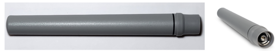
The Meraki outdoor ANT-20 is a dual-band omnidirectional antenna that appears cylindrical, supports both 2.4 and 5GHz bands, with a signal that radiates evenly in a 360-degree horizontal pattern around the antenna. These antennas are typically used on APs for client association due to the evenly distributed signal pattern.
Patch/Sector antennas are flat and either square or rectangular, and the RF signals are radiated and collected on the flat front surface of the antenna housing.
Patch and sector antennas can be single band (such as the 5GHz ANT-21 or 2.4GHz ANT-23) or can be dual band, such as the ANT-25 patch antenna or ANT-27 sector antenna.
Patch and sector antennas simply focus the RF energy in a particular direction. Typically, a sector antenna is more focused than a patch antenna and can transmit a signal further away, as well as “hear” signals from further away. These are commonly used to serve clients that will be gathered in a particular direction, as opposed to evenly spread all around the AP. Patch and sector antennas are also often used for wireless mesh connections or other point-to-point wireless links, since the signal is focused in a single direction for longer-distance links. For more information on the differences between patch and sector antennas, please refer to the datasheet library for the radiation patterns of the specific antenna.
Can I Wall-Mount Meraki APs with Internal Antennas?
Yes. Always consult the data sheet for the AP being deployed and examine the signal coverage patterns (azimuth/elevation charts) for both radios. Meraki indoor APs with integrated antennas tend to have more of a spherical coverage pattern by design. While the fully optimal AP placement tends to be horizontal, mounting from a ceiling between 3-4.5 meters (10-15 feet), wall-mounting the AP vertically is common, acceptable, and fully supported.
Which Antennas are Supported with Which Models of Access Points?
Meraki ANT-20/21/23/25/27 antennas are all supported on the MR-74/76/84/86 outdoor access points. Please refer to our datasheet library for more information, as well as for legacy MR access points and antennas.
The outdoor-rated tri-band CW-ANT-O1-NS-00 omnidirectional antenna, and outdoor-rated CW-ANT-D1-NS-00 patch antenna, are only supported on the outdoor-rated CW9163E WiFi-6E AP. These CW models of smart antennas are also self-identifying to the AP.
The Cisco Four-Port Dual-Band Polarization-Diverse Array stadium antenna (AIR-ANT2513P4M-N=) is certified and supported for use with MR84 and MR86 access points. This is common for stadium deployments for example.
Indoor MR access points, such as MR20, MR28, MR36, MR46, and MR56/57, as well as the indoor CW916x-MR models, do not support the use of external antennas, and instead have integrated omnidirectional antennas. Likewise, the outdoor MR70 and MR78 access point have integrated omnidirectional antennas and do not support external antennas.
One exception to this paragraph above is the indoor CW-9166D1-MR access point, which contains an integrated patch antenna. The CW9166D1 is a tri-band AP with three integrated patch antennas, 6 dBi and 70x70 degrees on the fixed 2.4GHz radio, 6 dBi and 70x70 degrees on the fixed 5GHz radio, and 8 dBi and 60x60 degrees on the flex 5/6GHz XOR radio.
The indoor access points with external antennas, such as the Wi-Fi 5 MR42E, MR53E, and Wi-Fi 6 MR46E, support a family of indoor smart antennas. There are six types identified by the letters A through F. Types A and B are omnidirectional, while types C-F are directional smart antennas that have integrated “pigtail” cables and also self-identify to the access point.
Can New WiFi-6E Antennas Be Used On Older Pre-6E Access Points?
No this is not recommended or supported. The tri-band CW-ANT-O1-NS-00 omnidirectional and CW-ANT-D1-NS-00 patch antennas are only supported on the newer outdoor CW9163E WiFi-6E tri-band AP, and should not be used on the MR74/76 or MR84/86 access points.
Do not use ANT-20/21/23/25/27 antennas on the CW9163E, and likewise do not use CW-ANT-O1-NS-00 or CW-ANT-D1-NS-00 on earlier MR AP models such as MR74/76/84/86.
Can Older Antennas Be Used On New WiFi-6E Access Points?
No this is not recommended or supported. For example, the ANT-20/21/23/25/27 antennas are only dual-band, not tri-band and should only be used on MR74/76/84/86 access points. These older, dual-band antennas are not tested, certified, or supported on the CW9163E access point for example.
This also applies to the AIR-ANT2513P4M-N= stadium antenna, which is not supported on the newer outdoor tri-band APs such as the CW9163E. CW9163E is a tri-band 2x2 AP. The AIR-ANT2513 stadium antenna is 4x4 and for 2.4/5GHz usage. On the CW9163E access point, there are two ports that are band-specific 6GHz on one side of the AP, and two dual-band 2.4/5GHz ports on the other side of the AP. The AIR-ANT2513P4M-N= should not be used on any tri-band access points. For a directional patch antenna for the CW9163E, that is the CW-ANT-D1-NS-00.
Even though the CW9163E access point has two dual-band 2.4/5GHz ports, do not use older dual-band ANT-20/25/27 antennas on the dual-band ports of the CW9163E. These are not tested or certified for use on newer WiFi-6E or newer access points and can potentially violate regulatory rules.
What are the Models of Outdoor Meraki Antennas?
MA-ANT-20: Meraki 4dBi/7dBi Dual-Band Omni Antennas, set of 2

MA-ANT-21: Meraki 5 GHz MIMO 13 dBi Sector Antenna

MA-ANT-23: Meraki 2.4 GHz MIMO 11dBi Sector Antenna

MA-ANT-25: Meraki Dual-Band 8dBi / 6.5dBi Patch Antenna (use quantity 2 if using with 4x4:4 APs)

MA-ANT-27: Meraki Dual-Band 9dBi/12dBi Sector Antenna (use quantity 2 if using with 4x4:4 APs)

AIR-ANT2513P4M-N Cisco Aironet Four-Port Dual-Band Polarization-Diverse Array Antenna (Stadiums)
AIR-ANT2513P4M-N does not include antenna cables, see Q&A below for details.


CW-ANT-O1-NS-00 is a tri-band 2.4/5/6 GHz 4/8/8 dBi omnidirectional self identifying antenna
Note: CW-ANT-O1-NS-00 is sold individually (not sold in a set of two like ANT-20).
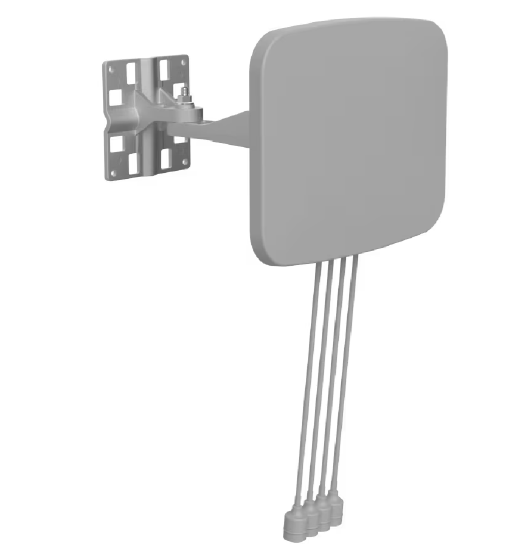
CW-ANT-D1-NS-00 is a 2x2 4-Port tri-band 2.4/5/6 GHz 8/9/9 dBi directional patch self-identifying antenna with four integrated cables
What are the details regarding the newer CW-ANT-O1-NS-00 antenna?
The CW-ANT-O1-NS-00 is the outdoor-rated tri-band (TRE) self-identifying omnidirectional antenna. We traditionally use the terminology SRE and DRE for Single/Dual Radiating Element. Antennas are "tuned" to radiate RF energy ideally on specific frequencies. If that is a single specific frequency range, such as with the ANT-21, it is referred to as a Single Radiating Element, meanwhile the ANT-25 has Dual Radiating Elements.
The CW-ANT-O1-NS-00 is TRE, Triple Radiating Element and is tuned to all three bands 2.4, 5 and 6GHz. This antenna has 4 dBi gain for 2.4GHz, 8 dBi gain for 5GHz, and 8 dBi gain for 6GHz. The X-plane azimuth is omnidirectional 360° and the Y-plane elevation/vertical half-power beamwidth is 30°. These are also smart antennas that self-identify to the access point that also contains the ability to identify antenna models.
Note: There are no CW-ANT-O1-NS-00 included when purchasing the access point (CW-9163E-MR for example). These antennas are sold individually (they are not sold in pairs like the ANT-20).
Note: The third set of characters "O1" in the antenna SKU CW-ANT-O1-NS-00 uses the capital letter 'O' for Omnidirectional (not the number zero).
What are the details regarding the newer CW-ANT-D1-NS-00 antenna?
The CW-ANT-D1-NS-00 is the outdoor-rated tri-band (TRE) self-identifying 2x2 directional patch antenna. We traditionally use the terminology SRE and DRE for Single/Dual Radiating Element. Antennas are "tuned" to radiate RF energy ideally on specific frequencies. If that is a single specific frequency range, such as with the ANT-21, it is referred to as a Single Radiating Element, meanwhile the ANT-25 has Dual Radiating Elements.
The CW-ANT-D1-NS-00 is TRE, Triple Radiating Element and is tuned for all three bands 2.4, 5 and 6GHz. This antenna has 8 dBi gain for 2.4GHz, 9 dBi gain for 5GHz, and 9 dBi gain for 6GHz. All three antenna elements have a half power beamwidth of 70° azimuth x 30° elevation. These are also smart antennas that self-identify to the access point that also contains the ability to identify antenna models.
This antenna is also paintable, with the same caveats that apply to the AIR-ANT2513P4M-N stadium antenna, such as making sure non-metallic paint for plastic applications is used.
Note: This antenna comes out of the box with a full accessory kit for mounting, including the CW-MNT-ART2-00 articulating arm/mount (this is the same wall/pole mount used for the CW9166D1). The antenna ships with all accessories for grounding, cable glands and dust caps. When purchasing the CW-ANT-D1-NS-00, no additional parts/SKUs need to be ordered. It also has four integrated 24-inch (0.6m) pigtail cables wit N connectors and flexible weather boots.
Note: The physical size of the CW-ANT-D1-NS-00 is very similar to the CW9163E AP itself. There is not a significant size difference such as with the AIR-ANT2513P4M-N. The CW9163E AP is 245 x 245 x 63.5 mm (9.64" x 9.64" x 2.5") so the CW-ANT-D1-NS-00 is roughly the same LxW size as the AP, the antenna being roughly 1 inch (23mm) wider and 1.5 inches (35mm) shorter.
Is there a quick reference sheet comparing these outdoor antennas?
Yes, here are some quick reference tables for the Cisco Meraki outdoor antenna models.
Please refer to the data sheets for additional details.
| Antenna SKU | Type | Band(s) | 2.4 GHz Gain | 5 GHz Gain | 6 GHz Gain | Density | Half Power Beamwidth * |
|---|---|---|---|---|---|---|---|
| MA-ANT-20 | Omni | Dual | 4 dBi | 7 dBi | - | Any | H: 360° V: 45°/45° |
| MA-ANT-21 | Sector | 5 GHz | N/A | 13 dBi | - | High | H: 80° V: 30° |
| MA-ANT-23 | Sector | 2.4 GHz | 11 dBi | N/A | - | High | H: 70° V: 40° |
| MA-ANT-25 | Patch | Dual | 8 dBi | 6.5 dBi | - | Medium / High | H: 60°/75° V: 70°/84° |
| MA-ANT-27 | Sector | Dual | 9 dBi | 12 dBi | - | High | H: 86°/65° V: 34°/18° |
| AIR-ANT2513P4M-N | Patch | Dual | 13 dBi | 13 dBi | - | Very High | H: 31°/31° V: 33°/27° |
| CW-ANT-O1-NS-00 | Omni | Tri | 4 dBi | 8 dBi | 8 dBi | Any | H: 360° V: 30°/30°/30° |
| CW-ANT-D1-NS-00 | Patch | Tri | 8 dBi | 9 dBi | 9 dBi | Medium | H: 70°/70°/70° V: 30°/30°/30° |
* Half Power (-3dB) Beam Width listed for both horizontal (azimuth) and vertical (elevation).
* Number pairs or triplets such as 60°/75° or 70°/70°/70° are listed as 2.4GHz value / 5GHz value - 6GHz value.
| Antenna SKU |
Dimensions |
Weight |
|---|---|---|
| MA-ANT-20 | 1.0 x 7.1" (25 mm x 180 mm) | 0.17 pounds (2.72 oz, 0.079 kg) |
| MA-ANT-21 | 9.2 x 5.5 x 1.6” (233 mm x 140 mm x 40 mm) | 1.2 pounds (19.2 oz, 0.527 kg) |
| MA-ANT-23 | 9.2 x 5.5 x 1.6” (233 mm x 140 mm x 40 mm) | 1.2 pounds (19.2 oz, 0.525 kg) |
| MA-ANT-25 | 7.1 x 7.1 x 1.6” (180 mm x 180 mm x 1.8 mm) | 1.1 pounds (17.6 oz, 0.512 kg) |
| MA-ANT-27 | 9.1 x 5.5 x 1.9” (230 mm x 140 mm x 48 mm) | 1.4 pounds (0.630 kg) |
| AIR-ANT2513P4M-N | 20 x 14.5 x 0.8" (507 mm x 368 mm x 21.1 mm) | 5.1 pounds (81.1 oz, 2.3 kg) |
| CW-ANT-O1-NS-00 | 1.0 x 8.875" (25 mm x 225 mm) | 0.25 pounds (4.06 oz, 0.115 kg) |
| CW-ANT-D1-NS-00 | 10.58 x 8.28 x 1.38" (268.8 mm x 210.2 mm x 35 mm) * | 1.92 pounds (30.76 oz, 0.872 kg) * |
* Note: These values are for the antenna only, not including the one or both pieces of the articulating arm mount. See question and answer below regarding the details of the articulating arm mount.
| Antenna SKU |
Operating Temperature Range |
|---|---|
| MA-ANT-20 | –40° to 158° F (–40° to 70° C) |
| MA-ANT-21 | –40° to 158° F (–40° to 70° C) |
| MA-ANT-23 | –40° to 158° F (–40° to 70° C) |
| MA-ANT-25 | –40° to 158° F (–40° to 70° C) |
| MA-ANT-27 | –40° to 158° F (–40° to 70° C) |
| AIR-ANT2513P4M-N | –40° to 185° F (–40° to 85° C) |
| CW-ANT-O1-NS-00 | –40° to 158° F (–40° to 70° C) |
| CW-ANT-D1-NS-00 | –40° to 158° F (–40° to 70° C) |
What are the Details Regarding the Articulating Arm Mount?
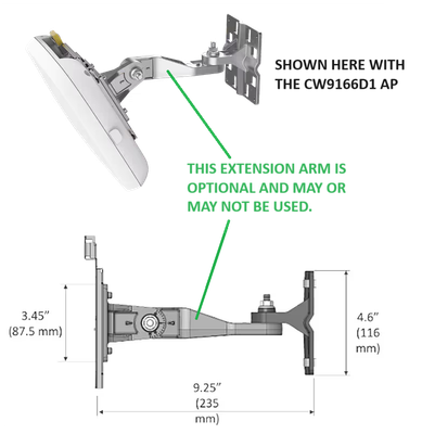
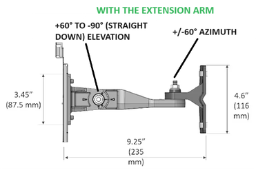
The CW-MNT-ART2-00 is for wall or pole mounting, and may be used with the CW9166-D1 AP or CW-ANT-D1-NS-00 antenna. It has a 116x116 mm main frame mount that connects to a wall or pole, an 87x87 mm AP frame mount, and a 235 mm long mounting arm.
Note that with the CW-MNT-ART2-00, the extension arm is optional. It is included with the mounting hardware, but may not be required depending on the type of installation. This gives rise to the "single pivot" (no extension arm) and "dual pivot" (with extension arm) types of mounting. See the images below.
Without the extension arm, there is a single pivot point and this single axis allows for +/- 50° of adjustment (left image).
Using the extension arm, there are two pivot points allowing for +/- 60° of azimuth and +60° to -90°of elevation (right image).

Given there are both single or dual pivot installation types, this gives rise to two corresponding weights and measures (see below).
Antenna only: 1.92 pounds (30.76 oz, 0.872 kg)
Antenna with single pivot (without extension arm) CW-MNT-ART2-00: 2.9 pounds (1.32kg)
Antenna with dual pivot (with extension arm) CW-MNT-ART2-00: 3.3 pounds (1.5kg)
Antenna only: 10.58 x 8.28 x 1.38" (268.8 mm x 210.2 mm x 35 mm)
Antenna with CW-MNT-ART2-00 single pivot (without extension arm), fully extended: 10.58" X 8.28" X 5.5" (268.8 X 210.2 X 140 mm)
Antenna with CW-MNT-ART2-00 dual pivot (with extension arm), fully extended: 10.58" X 8.28" X 10.63" (268.8 X 210.2 X 270 mm)
What are the Models of Indoor External Antennas?
5-port 3x3:3 AP models: MR42E
(MR42E EoS April 2022)
MA-ANT-3-A5, Indoor fixed dipole dual-band omni antennas, 5-pack

MA-ANT-3-B5, Indoor bendable dipole dual-band omni antennas, 5-pack

MA-ANT-3-C5, Indoor dual-band omni antenna, 5-port

MA-ANT-3-D5, Indoor dual-band downtilt omni antenna, 5-port

MA-ANT-3-E5, Indoor dual-band wide patch antenna, 5-port

MA-ANT-3-F5, Indoor dual-band narrow patch antenna, 5-port

6-port 4x4:4 AP models: Wi-Fi 5 MR53E, Wi-Fi 6 MR46E
(MR53E EoS April 2022)
MA-ANT-3-A6, Indoor fixed dipole dual-band omni antennas, 6-pack

MA-ANT-3-B6, Indoor bendable dipole dual-band omni antennas, 6-pack

MA-ANT-3-C6, Indoor dual-band omni antenna, 6-port
MA-ANT-3-D6, Indoor dual-band downtilt omni antenna, 6-port
MA-ANT-3-E6, Indoor dual-band wide patch antenna, 6-port
MA-ANT-3-F6, Indoor dual-band narrow patch antenna, 6-port
Also note the 'A' and 'B' antennas are available as single units:
MA-ANT-3-A1, Indoor fixed dipole dual-band omni antenna, 1-pack

MA-ANT-3-B1, Indoor bendable dipole dual-band omni antennas, 1-pack

Is there a quick reference sheet comparing these indoor antennas?
Yes, here is a basic quick reference for the 6-element models for the MR46E access point. Note that the A and B models may also be purchased as single units and those SKUs simply end with A1 or B1. There are also A5 - F5 SKUs which are for the (now End-of-Sale) MR42E access point.
| SKU | Antenna Type | Band(s) | 2.4 GHz Gain | 5 GHz Gain | Density | HPBW | Typical Ceiling Height |
|---|---|---|---|---|---|---|---|
| MA-ANT-3-A6 | Dipole | Dual | 3.8 dBi | 5.5 dBi | Low | H: 360° V: 40°/40° | 8-15 ft (2.5-4.5m) |
| MA-ANT-3-B6 | Bendable Dipole | Dual | 3 dBi | 5.7 dBi | Low | H: 360° V: 40°/40° | 8-15 ft (2.5-4.5m) |
| MA-ANT-3-C6 | Panel Omni | Dual | 4.9 dBi | 4.9 dBi | Low | H: 360° V: 60°/60° | 8-15 ft (2.5-4.5m) |
| MA-ANT-3-D6 | Panel Downtilt Omni | Dual | 2.4 dBi | 3.7 dBi | Medium | H: 360° V: 60°/60° *** | 12-25 ft (4-8m) |
| MA-ANT-3-E6 | Wide Patch | Dual | 7 dBi | 6.3 dBi | Low or High | H: 60/60° V: 60°/60° | 12-25+ ft (4-8+ m) * |
| MA-ANT-3-F6 | Narrow Patch | Dual | 11.2 dBi | 10.8 dBi | Low or High | H: 30/30° V: 30°/30° | 25+ ft (8+ m) ** |
* The E6 wide patch antenna may work equally well for higher ceilings over 25 feet (8 meters) in lower client density deployments, as well as mounting up to 25 feet (8 meters) in higher density deployments. It is always recommended to conduct a proper site survey to determine ideal antenna type, placement, mounting height and angle.
** The F6 narrow patch can be more ideal for smaller coverage zones coupled with higher ceilings, such as with certain lecture halls, stadiums, and event centers.
Note: Despite the names of the E6 being "wide patch" and F6 being "narrow patch" be aware this refers to the coverage. The E6 has a 60-degree half-power beamwidth cone of coverage, while the F6 has a 30-degree half-power beamwidth cone of coverage. Wide and narrow does not refer in any way to the dimensions of the antennas. The F6 narrow patch is significantly larger (more than double the length and width) than the E6 wide patch. Please refer to the dimensions and weight table below.
*** The MA-ANT-3-D6 downtilt omni half power beam width of 60°/60° for 2.4/5GHz is aimed at a 45° electronic down tilt.
| SKU | Dimensions | Weight | ||||
|---|---|---|---|---|---|---|
| MA-ANT-3-C6 | 11.81” diameter x 1.38” (300 mm x 35 mm) | 2.3 pounds (37.04 oz, 1.05 kg) | ||||
| MA-ANT-3-D6 | 8.86” diameter x 1.46” (225 mm x 37 mm) | 1.3 pounds (20.81 oz, 0.59 kg) | ||||
| MA-ANT-3-E6 | 10.83” x 10.83” 0.93” (275 mm x 275 mm x 23.5 mm) | 2.6 pounds (41.27 oz 1.17 kg) | ||||
| MA-ANT-3-F6 | 25.98” x 20.87” 5.12” (660 mm x 530 mm x 130 mm) | 7.1 pounds (113.6 oz, 3.2 kg) | ||||
Why Are There Five or Six Antenna Ports on Indoor "E" Models?
The MR42E is a 3x3:3 access point with three dual-band client-serving antennas. The MR53E and MR46E are both 4x4:4 access points with four dual-band client-serving antennas. The reason these APs have five and six ports, respectively, is because they also have a third dedicated dual-band scanning radio for full-time WIPS and spectrum analysis, as well as a fourth radio for BLE/IoT applications. These antennas are designed to provide matching coverage patterns across all four radios.
How Do I Attach an Antenna to Outdoor APs?
All Cisco Meraki outdoor antennas use a standard N-type connector, allowing them to be screwed into the antenna mounts on the access point. The omnidirectional ANT-20 antennas attach directly, while the patch and sector antennas have prefabricated “pigtail” cables with N connectors to connect to the access point.
When attaching antennas:
- Omnidirectional antennas should be attached in pairs, with a complete pair on the top and/or bottom. It is not recommended to only attach one omni antenna to either band. That is, do not have any active antenna ports with no antenna connected. Refer to the additional question in the FAQ regarding operation of an AP without an antenna.
- Meraki outdoor sector and patch antennas have two integrated cables and N connectors. Both of these connectors must be attached to the same radio. This is important for 2x2:2 APs such as MR74 and MR76. A single sector/patch antenna should not be attached to both the top and bottom of the access point, which would have that antenna connected to two different radios. When looking at these 2x2:2 access points, each radio has two ports next to each other on the same side of the AP. For example, if an MR76 has two ANT-25 patch antennas properly connected, even though they are dual band antennas, one ANT-25 will have both pigtail cables connected to the 2.4GHz radio and the other ANT-25 will be connected to the two 5GHz radio ports.
- In the case of the AIR-ANT2513P4M-N stadium antenna for use with the MR84 or MR86, there are no prefabricated cables with N connectors to connect to the access point. Separate antenna cables will be required. Antenna ports A and B connect to antenna ports on one side of the AP and antenna ports C and D connect to the other side of the access point. Additional details are in a separate question below.
Can I leave unused connectors uncovered?
No. In certain use cases, you may have one radio of a 2x2 access point disabled, for example the 2.4GHz radio on an MR76 might be off/unused, and therefore the two 2.4GHz antenna ports might not have antennas connected. (See next question below.) Those antenna ports should still be covered with weatherproof caps. It is required to cover all unused connectors on an outdoor AP to prevent damage that would void the unit's warranty.
If a connector does not have an antenna attached, a waterproof N-type cover (Meraki recommends N-type dust caps) should be used to seal the connection.
Note: The included covers are used to protect the unit during shipping. They are not waterproof, and therefore not recommended for deployment.
For indoor APs with external antennas, there should be no unused antenna ports. The indoor external antennas have either five integrated cables (for an MR42E) or six integrated cables (for MR53E and MR46E) and are made to match 1:1 with the antenna ports on the AP. If using the ‘A’ or ‘B’ type indoor external connectors, they come in quantities of five or six so there is a 1:1 match. For indoor APs with external antennas, there should be no unused ports or cables.
Can I leave any AP antenna connectors unused?
It depends. In some outdoor cases, with a 2x2:2 access point like the MR74 and MR76, they have band-specific antenna ports, two for 2.4GHz on the top of the AP and two 5GHz ports on the bottom of the AP, and they are labeled as such. There may be certain designs or reasons to have one radio disabled. In that case, for example if the 2.4GHz radio is disabled, then you would not have any antenna(s) connected to the 2.4GHz antenna ports. And in that scenario, you should still have those ports properly covered (see previous question above).
On a 4x4:4 AP however such as the MR84 and MR86, there should be no unused ports. These APs have four dual-band antenna ports (and therefore do not have 2.4 or 5GHz labels). None of these ports should be left unconnected because all four ports will always be active even if one radio is disabled. MR84/86 APs should have all four antenna ports connected, and with the same type of antennas with the same orientation.
For indoor APs such as the MR46E with six ports, all six ports should have connections (see above question).
Will it damage the AP if I run it with no antennas connected, such as temporarily in a lab?
This is not recommended. If an AP is being “primed” in a temporary lab or staging area for example, a common practice is to have some spare ANT-20 omnidirectional antennas available if the AP will be running for a short period of time in such an environment.
Theoretically, yes, there is possible harm to the AP from running empty antenna ports. This causes an impedance mismatch and a nearly full-strength signal reflection back into the transmitter, causing energy loss. When working with RF this energy loss is in the form of heat and gives rise to the term thermal impedance, basically a measure of heat loss in degrees Celsius per watt. This is an indication of how much the equipment can heat up. This can damage RF equipment by (eventually) burning out the transmitter’s electronics. This is typically not a catastrophic failure all at once, but a cumulative one that can cause the equipment to fail prematurely.
Can I use a single MA-ANT-2x on an MR84/86?
No, a single ANT-21/23/25/27 is not supported or recommended on these 4x4:4 APs. (See previous question above.)
Are there any special considerations when using the Cisco AIR-ANT2513P4M-N antenna on MR84 or MR86?
Yes, there are some special considerations for stadium-type deployments.
- The AIR-ANT2513P4M-N (stadium) antenna does not come with pre-attached cables like ANT-25 or ANT-27 for example. Customers will need to provide four lengths of antenna cables with N connectors on both ends, such as the Cisco AIR-CAB005LL-N cable or an equivalent high-quality cable, the shorter the better to minimize loss.
- AIR-ANT2513P4M-N is a narrow patch antenna, but physically larger than other types of external antennas. This stadium antenna is roughly 15x20 inches (37x51 cm) in case that factors into aesthetics and mounting options/ locations.
- Unlike some antennas, this stadium antenna is paintable to blend in with what is behind it. Use non-metallic paint (and primer if needed) that is made for plastic applications. Refer to the AIR-ANT2513P4M-N antenna installation guide.
- For the antenna port connections, the AIR-ANT2513P4M-N antenna has ports labeled A/B/C/D. They have V/H/V/H polarization, respectively. On the MR84 and MR86 there are no matching designations. The two ports on either side of the MR86 are 1H+1V. So the "top" 2 ports of the MR84/86 can go to ports A/B and the "bottom" two ports of the MR84/86 can go to ports C/D. The left vs. right port on each side of the AP isn't important since the end result will be 2H+2V.
- Antenna extension cables can be fairly rigid. Try to mount the antenna and the AP in such a way that all four antenna connectors can easily reach all four AP connectors, without putting any stress or kinks in the antenna cable, which can change its characteristics and add loss. You may tie-wrap and dress up the cables, but avoid any small diameter bends and refer to the cabling manufacturers guidelines.
- Determine if lightning arrestors are needed or appropriate since there will be lengths of coaxial antenna cable, so have a qualified WLAN installer review if arrestors are required and review the building/safety standards and proper electrical grounding requirements. There is no Meraki SKU for lightning arrestors, and Cisco AIR-ACC245LA-N can be used.
How Do I Determine Which Bands are Supported?
All dual-band 2x2:2 outdoor APs (such as MR74 and MR76) have two sets of antenna connectors: the top two are for the 2.4GHz radio and the bottom two are for the 5GHz radio.
Dual-band 4x4:4 outdoor APs (such as MR84 and MR86) have both the 2.4 GHz and 5 GHz radios diplexed onto each antenna port, thus dual-band antennas should be paired with the AP.
The model of the antenna denotes whether it should be connected to the 2.4GHz or 5GHz mount points, or if it supports both. Supported bands are also color coded on the antenna's base, where green denotes 2.4GHz support, blue denotes 5GHz support, and both green+blue indicates that the antenna is dual-band.
The omni antenna pictured below, for example, supports both bands:
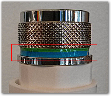
Note: The older MR62 (end-of-sale 2017, supported through 2024) is a single-band radio and only has 2.4GHz mount points. ANT-20 may be used with that AP without issue, as there is no band-specific omnidirectional antenna option.
For more information on differences between each band, please refer to our documentation article Channel Planning Best Practices.
Can I Mix Antenna Types on Outdoor APs?
It depends. On 2x2:2 outdoor access points, such as MR74/76, there are use cases for mixing antenna types, such as when creating a mesh link. For example, there might be a distant outdoor area that needs client coverage. An MR76 mesh AP can be deployed with ANT-20 omni antennas on the 2.4GHz ports to serve clients in the area around the access point, while an ANT-27 sector antenna can be connected to the 5GHz ports of the MR76 and aimed back at a gateway AP on the building to create a 5GHz backhaul mesh link.
On 4x4:4 outdoor access points, such as MR84 and MR86, all four antenna ports are dual-band and diplexed to both radios. On these APs, all antennas should be identical and have the same orientation. Do not mix omni and patch antennas or patch and sector antennas, for example, on 4x4:4 access points.
Note: For 4x4:4 APs such as MR84/86, all 4 ports should be connected to the same type of antenna and those antennas should have the same orientation.
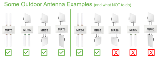
Here are some common examples of outdoor AP and antenna combinations, as well as examples of what is not supported. Note this is not an exhaustive list of possible combinations.
In this series of images below, there are different combinations of ANT-20 (omni), ANT-25 (patch) and ANT-27 (sector) connected to MR76 and MR86. Looking closely, you may notice some of the directional antennas aimed in different directions.
For example, the first red 'X' is an MR86 with ANT-25 antennas aimed in different directions, which is not supported (see the next Q&A immediately below which describes why).
Can I Aim Directional Antennas in Different Directions on the Same AP to Increase Coverage?
No, this is not recommended.
On a 4x4:4 access point, such as MR84/86, all antennas should be the same type and have the same orientation. If, for example, there is an MR86 with two ANT-25 patch antennas connected, do not attempt to aim each antenna in different directions in order to increase the coverage area. This will send two spatial streams in one direction and two spatial streams in another direction and will have unintended consequences.
With a 2x2:2 access point, such as MR74/76, antennas can be of different types and have different orientations, but NOT for the purpose of increasing the coverage area. In the example case of using a pair of ANT-25 patch antennas with different orientation, a 2x2:2 AP will end up sending the two 2.4GHz streams in one direction and the two 5GHz streams in another direction. While this could arguably increase the coverage area, it would be at the expense of single-band coverage in each area, which is likely unintended and can introduce client issues.
Can I Use a Third-Party Antenna?
Cisco Meraki outdoor access points use standard N-type antenna connectors, while indoor access points with external antennas use RP-TNC connectors. Both are widely supported by different antenna manufacturers. Cisco Meraki antennas are strongly recommended to ensure optimal performance and assistance from Meraki support. Only Cisco Meraki antennas (and the Cisco stadium antenna on MR84/86) are fully certified and supported on Meraki access points.
Third-party antennas may be used when determined to be appropriate by a qualified WLAN specialist. Please note that any damage caused by use of a third-party antenna will not be covered by the device warranty. If a third-party antenna is used, it is the customer’s responsibility to plan accordingly and ensure the deployment is operating within the proper EIRP limits for their regulatory domain. Also note that Meraki Support will not be able to fully support coverage or performance issues when third-party antennas are in use.
What are Lightning Arrestors and Do I Need Them?
Lightning arrestors are not meant to protect equipment from direct strikes, but rather from nearby lightning strikes that could build up enough charge to have over-voltage transients that can cause damage to the radio equipment.
There is not a Meraki SKU for lightning arrestors, but you may use the Cisco Aironet lightning arrestor with N connectors (AIR-ACC245LA-N) when required on outdoor Meraki wireless APs/antennas. The arrestor is designed to protect the radio equipment from static electricity and lightning-induced surges that travel on coaxial transmission lines (antenna cables). Refer to our reference guide for more information on AIR-ACC245LA-N.
These systems need to be properly grounded according to the hardware installation guides. Proper grounding should be completed or confirmed by qualified electricians.
Note: Lightning arrestors are needed where a nearby lightning strike could induce harmful conditions on a length of coax cable. If your installation with ANT-20 omnidirectional antennas does not leverage antenna extension cables, then there is no coaxial cable, and the antennas are directly attached to the AP. In this scenario there is no need to install a lightning arrestor as an inline barrel connector. It is still important however to make sure the whole unit (AP + directly attached omni antennas) is properly grounded via the chassis of the AP.
Note: If an installation involves mounting an AP outside and the antenna leads (coax cable extensions) are coming through a wall inside a building (or vice-versa), then each of the four antenna leads should have lightning arrestors (on each cable) prior to entering the building and properly taken to ground.
The main concern is protecting the equipment inside the building, and some installations may also call for lightning protection on the Ethernet cable entering the building as opposed to lightning arrestors on the antenna cables. Arrestors would be used where coaxial antenna cabling comes into a building and especially areas where there is a significant length of exposed outdoor coax cable. In other installations, it may be more appropriate to properly ground the outdoor AP and leverage an RJ45-based lightning/surge protector for Gateway-mode APs that are wired back to an access switch. Always consult with a WLAN specialist who can advise the proper grounding design for your specific installation.
Can I use Outdoor Antennas on Indoor APs?
No, this is not supported. The indoor access points with external antennas, such as MR53E and MR46E, use indoor smart antennas that self-identify themselves over the IoT connection to the access point. Current outdoor antennas do not include this self-identification capability.
In addition, the indoor smart antennas use RP-TNC connectors, while the outdoor antennas use N connectors. Furthermore, even if outdoor antennas with connection adapters were used on indoor APs, the outdoor antennas do not have separate scanning and IoT radio connectors, which would leave those "scan" and "IoT" AP ports unconnected or require a third antenna set on the scanning/IoT ports in order to have the same coverage patterns across all four radios.
Can I Use Indoor Antennas on Outdoor APs?
No, this is not supported. If there are outdoor APs such as MR76/86 deployed indoors, the outdoor-rated antennas should still be used.
The indoor access points with external antennas, such as MR53E and MR46E, use indoor smart antennas that self-identify themselves to the access point. In addition to the connector types being different (RP-TNC versus N connectors), the indoor external antennas also have additional connections for the scanning and IoT radios that outdoor APs do not have.
Why are the 'A' and 'B' type external antennas not labeled?
The "smart" antennas that self-identify to the indoor APs such as MR53E and MR46E are the directional MA-ANT-3-C/D/E/F models that have this capability, and have their connectors labeled with 2.4/5, IoT or Scan.
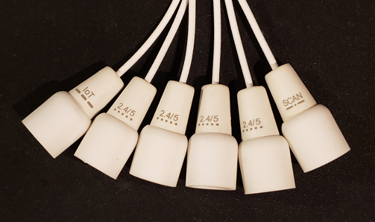
The MA-ANT-3-A5/A6 fixed dipoles and MA-ANT-3-B5/B6 bendable dipoles do not have any labels, all of the 'A' fixed dipole antennas are identical to one another, as are the 'B' antennas. Therefore it does not matter which 'A' or 'B' antennas in a set get connected to any one of the AP's antenna ports. Any ‘A’ or ‘B’ antenna type can be connected to any antenna port, without needing to consider if it is a client serving radio, the scanning radio, or the IoT radio.
Can I Use Antenna Extension Cables?
Yes. Keep in mind that extension cables and any connection adapters do add loss and should be calculated into the link budget. This loss of signal is directly proportional to the length of the cable, and this loss will decrease the range of coverage. Always use the shortest antenna extension cable possible in order to minimize loss.
There are no Meraki-specific SKUs for ordering antenna extension cables. You may order the standard Cisco Aironet/Catalyst antenna extension cables. For example, the five-foot and ten-foot low-loss antenna cable SKUs with N connectors are AIR-CAB005LL-N= and AIR-CAB010LL-N=. For RP-TNC extension cables, the SKUs look the same but are designated with -R instead of -N, such as AIR-CAB005LL-R=.
What are the Antenna Extension Cable Options?
| Part Number | Length | Connectors (RA = right angle) | Type | dB Loss 2.4 / 5 GHz | Installation Type |
| AIR-CAB005LL-N | 5 feet | N Plug to RA N Plug | LMR-400 | 0.5 / 0.8 | Indoor / Outdoor / Direct Bury |
| AIR-CAB010LL-N | 10 feet | N Plug to RA N Plug | LMR-400 | 0.9 / 1.5 | Indoor / Outdoor / Direct Bury |
| AIR-CAB005LL-R | 5 feet | RP-TNC Plug to RP-TNC Jack | LMR-400 | 0.5 / 0.8 | Indoor / Outdoor / Direct Bury |
| AIR-CAB005PL-R | 5 feet | RP-TNC Plug to RP-TNC Jack | LMR-195 | 1.1 / 1.8 | Indoor / Plenum |
| AIR-CAB005LL-R-N | 5 feet | RA N Plug to RP-TNC Plug | LMR-240 | 0.5 / 0.8 | Indoor / Outdoor / Direct Bury |
The terminology "plug" is also commonly known as "pin" or "male", and "jack" is also commonly known as "socket" or "female".
See also the Cisco RF Cables and other accessories documentation here.
What are the Antenna Mounting Arm Options?
| MA-MNT-ANT-1 | Standard 8.7" mounting arm for E & F series patch antenna |
| MA-MNT-ANT-2 | Long 13" mounting arm for E & F series patch antenna |
| MA-MNT-ANT-3 | Horizontal mounting bracket for C & D series omni antenna |
| MA-MNT-ANT-4 | Vertical mounting bracket for C & D series omni antenna |
| MA-MNT-ANT-5 | Threaded Extension Arm for all surface-mount C/D/E/F Antennas |
| MA-MNT-ANT-6 | Meraki Outdoor Antenna (21/23/25/27) Replacement Mounting Kit |
| CW-MNT-ART2-00 | Replacement articulating wall/pole mount for CW9166D1 and CW-ANT-D1-NS-00 |
My Outdoor Antenna Mount was Broken in a Storm, Can I Replace it?
Yes. the correct SKU to order is MA-MNT-ANT-6 which is the Meraki outdoor antenna (ANT-21/23/25/27) replacement mounting hardware. In some unusual cases where a powerful storm might break the antenna mount but the antenna itself is still viable, you may order only the mounting hardware to re-mount the antenna.
In the case of the newer CW9163E AP or the CW-ANT-D1-NS-00 patch antenna, if any accessory parts are lost or broken, there is a separate CW9163E accessory kit (CW-ACC-KIT1-00) that may be purchased separately.
The CW-ACC-KIT1-00 contains:
- 1 grounding lug
- 2 grounding screws
- 5 RJ45 cable glands
- 4 waterproof N-type caps
- 1 GPS connector cap
- 2 RJ45 dust caps
- 2 reset button caps
If the CW-MNT-ART2-00 articulating arm/mount breaks (such as during a powerful storm) then it may also be purchased separately to replace a broken arm mount.
Is there a list of SKUs available for replacement AP mounting kits?
Yes, indeed. This is the full list in the table below.
Note that some SKUs for much older EoS APs are also now End-of-Sale.
| MA-MNT-MR-1 (EoS) | Replacement mounting kit for MR12/MR16 |
| MA-MNT-MR-2 (EoS) | Replacement mounting kit for MR62/MR66 |
| MA-MNT-MR-3(EoS) | Replacement mounting kit for MR34 |
| MA-MNT-MR-4 (EoS) | Replacement mounting kit for MR18 |
| MA-MNT-MR-5 (EoS) | Replacement mounting kit for MR26 |
| MA-MNT-MR-6 (EoS) | Replacement mounting kit for MR32 |
| MA-MNT-MR-7 (EoS) | Replacement mounting kit for MR72/MR74 |
| MA-MNT-MR-8 (EoS) | Replacement mounting kit for MR42 |
| MA-MNT-MR-9 (EoS) | Replacement mounting kit for MR52/MR53/MR53E |
| MA-MNT-MR-10 (EoS) | Replacement mounting kit for MR84 |
| MA-MNT-MR-11 (EoS) | Replacement mounting kit for MR33 |
| MA-MNT-MR-12 | Replacement mounting kit for MR20 |
| MA-MNT-MR-13 | Replacement mounting kit for MR70 |
| MA-MNT-MR-14 | Replacement mounting kit for MR55 |
| MA-MNT-MR-15 | Replacement mounting kit for MR45 |
| MA-MNT-MR-16 | Replacement mounting kit for MR76/MR86 |
| MA-MNT-MR-17 | Replacement mounting kit for MR36 |
| MA-MNT-MR-18 | Replacement mounting kit for MR46E |
| MA-MNT-MR-H1 (EoS) | Replacement mounting kit for MR30H (Use H1A) |
| MA-MNT-MR-H2 | Surface mounting kit for MR30H/MR36H |
| MA-MNT-MR-H3 (EoS) | Port security mounting kit for MR30H (Use H3A) |
| MA-MNT-MR-H1A | Meraki Replacement Wall plate Mounting Kit for MR30H/MR36H |
| MA-MNT-MR-H3A | Meraki Wired Guest Port Cover Mounting Kit for MR30H/MR36H |
Are there T-rail or universal mount adapters for Meraki APs?
Yes, you may order any of these SKUs separately:
- MA-MNT-CLG-1 - Meraki T-Rail Channel Adapter Mount Kit
- MA-UMNT-MR-A2 - Meraki MR Adaptor for Cisco Universal Mounts
- MA-UMNT-MR-A3 - Meraki MR Adaptor for Aruba Universal Mounts
Additional Resources
For more information on using antennas, MR access points, and wireless in general, please refer to the following sites and documentation: