
Deploying Enterprise-Ready Generative AI on VMware Private AI
Introduction
Executive Summary
Generative artificial intelligence (GenAI), especially in the form of Large Language Models (LLMs), is at the forefront of technological innovation, offering human-like creativity, reasoning, and language understanding. Organizations across the globe recognize its potential, but implementing LLMs, particularly in regulated industries, brings about unique challenges. On-premises deployment in the private cloud offers a strategic solution, allowing organizations to retain complete control over data and comply with industry regulations. This fosters trust and transparency, ensuring that sensitive information and intellectual property are securely protected within enterprise environments.
IT organizations now can use VMware Private AI platform for running GenAI models. This platform for AI services enables privacy and control of corporate data, choice of open source and commercial AI solutions, quick time-to-value, and integrated security and management.
Utilizing VMware Private AI, we can democratize GenAI by igniting business innovation for all enterprises and providing the following advantages:
- Get the flexibility to run a range of AI solutions for your environment: NVIDIA, open–source, and independent software vendors.
- Deploy with confidence, knowing that VMware has partnerships with NVIDIA and other partners, all of whom are respected leaders in the high-tech space
- Achieve great performance in your model with vSphere and VMware Cloud Foundation's GPU integrations.
- Augment productivity by building private chatbots, eliminating redundant tasks, and building intelligent process improvement mechanisms.
This white paper serves as an essential guide, providing insights into the architecture design, implementation, and best practices for LLM fine-tuning and inference. By embracing GenAI through the on-premises deployment of LLMs on VMware infrastructure, enterprises can unlock the full potential of this revolutionary technology in a responsible and ethical manner, significantly boosting innovation and driving sustainable growth.
Document Scope and Objectives
This white paper offers readers a detailed reference architecture that leverages VMware Private AI for GenAI workloads. A key focus of the white paper is to provide effective guidance on preparing, deploying, and automating virtual infrastructures fit for LLM fine-tuning and inference tasks. These tasks normally require the availability of hardware accelerators, such as GPU and Remote Direct Memory Access (RDMA) devices either from Virtual Machines (VMs) or containers. For that reason, we dedicate a big portion of this document to guide the reader through the integration of hardware accelerators and VMware environments.
Furthermore, the white paper presents examples of LLM fine-tuning and inference as the means for testing and validating the reference architecture deployment. The goal is to establish a scalable, high-performance, and production-ready architecture for GenAI tailored to meet the demands of enterprise-level applications.
Whether you are a seasoned AI practitioner or just beginning your journey of GenAI, this white paper serves as a technical resource, providing step-by-step instructions, best practices, and real-world insights that help you run GenAI projects on top of VMs or Tanzu Kubernetes hosted by VMware Cloud Foundation and vSphere with Tanzu. By following the guidelines presented in this paper, you can confidently embark on the path toward developing cutting-edge GenAI solutions that drive innovation and success in your organization.
Architecture Design
High-level Architecture Overview
A high-level overview of the solution is depicted below starting with the infrastructure components up to the LLM application layer.

Figure 1: Solution High-Level Architecture Overview
Figure 1 illustrates the stacking of the software components used in LLM Operations starting from the AI and MLOps Platform and all the way up.
Customers can leverage the solution for two primary LLM workflows – customization (fine-tuning, prompt-tuning, and others) and inference at scale. Both workflows demand more computing capacity than traditional deep learning workloads regarding LLMs. Inference also requires GPU resources depending on application needs or number of users. By leveraging VMware Cloud Foundation and distributed computing frameworks like Ray, unused resources in an environment can be repurposed for machine learning (ML) workflows. This improves infrastructure utilization and boosts productivity for ML overall.
VMware Private AI Overview
VMware Private AI is an architectural approach that aims to balance the business gains from AI with the practical privacy and compliance needs of the organization. VMware Private AI is architected with industry partners to create a solution for AI services that ensures privacy and control of corporate data, choice of open source and commercial AI solutions, quick time-to-value, and integrated security and management. The optimized infrastructure stack comprising of VMware Cloud Foundation provides an optimized infrastructure stack for delivering Private AI within the Enterprise.
VMware Cloud Foundation Overview
Integrating LLM with VMware Cloud Foundation set the scene for a new era of capabilities and opportunities for enterprises. VMware Cloud Foundation is a turnkey platform that stands out as an ideal choice for deploying AI workloads due to its integrated infrastructure management, which simplifies complex tasks. The platform ensures consistency across various cloud environments, facilitating seamless AI workload deployment. Its scalability capabilities meet the resource demands of AI tasks, while resource efficiency features optimize infrastructure utilization. The platform's automated lifecycle management streamlines updates and upgrades, minimizing disruptions to AI operations. Furthermore, the platform's integration with AI-specific hardware accelerators further amplifies performance potential.

Figure 2: VMware Cloud Foundation Architecture
VMware Cloud Foundation for AI workloads yields benefits such as simplified management, enhanced scalability, improved security, and optimized resource usage, positioning organizations to harness the full potential of artificial intelligence within a resilient and efficient infrastructure.
VMware vSphere with Tanzu Overview
VMware vSphere with Tanzu, transforms traditional virtualization infrastructure into a robust platform for containerized workloads. VMware Tanzu Kubernetes Grid™ facilitates the creation and management of Tanzu Kubernetes Cluster (TKC) natively within vSphere, seamlessly integrating Kubernetes capabilities with the reliable features of vSphere. With vSphere's networking, storage, security, and VMware vSphere High Availability (vSphere HA) features, organizations achieve better visibility and operational simplicity for their hybrid application environments.
Table 1: VMware vSphere AI Capabilities
|
vSphere with Tanzu - AI/ML Capabilities |
Description |
|
NVIDIA NVSwitch support |
For up to 8 GPUs per host, vSphere now supports the deployment of NVIDIA NVSwitch technology, improving large-size AI/ML workload performance by leveraging GPU to GPU direct communication. All 8 GPUs or a subset of them, can be allocated to a single VM. |
|
Device groups |
In VMware Cloud Foundation 5.0, device groups enable VM to group certain hardware devices simpler like Network Interface Card (NIC) and GPU devices to enhance the performance. Compatible vendor device drivers are required and subject to vendor release. NVIDIA will be the first partner supporting device groups with upcoming compatible drivers. |
|
Simplified hardware consumption with device groups |
Device groups leverage the existing Add New PCI Device to VM workflows. VMware vSphere Distributed Resource Scheduler™ (DRS) and vSphere HA are aware of device groups and will place VMs appropriately to meet the device groups’ requirements. |
|
Heterogeneous vGPU profile |
vSphere reduces cost by improving GPU utilization and reducing workload fragmentation in GPUs by the addition of support for heterogenous vGPU profiles on the same GPU. This capability allows different types of workloads to be configured with different GPUs, such as VDI applications, compute applications, graphics applications. |
vSphere with Tanzu also enables organizations to run application components in containers or VMs on a unified platform, streamlining workload management and deployment. By converging containers and VMs, IT teams can leverage the benefits of both paradigms while maintaining a cohesive and scalable infrastructure.
NVIDIA AI Enterprise Overview
![]()

Figure 3: NVIDIA AI Enterprise on VMware Cloud Foundation with Tanzu and VMware vSphere with Tanzu
NVIDIA AI Enterprise (NVAIE) is a robust suite designed to boost AI workloads in various industries. In partnership with VMware, NVAIE delivers virtual GPUs (vGPU) and Multi-Instance GPUs (MIG) for optimal performance of AI workloads running on VMware Cloud Foundation and Tanzu Kubernetes Grid. NVAIE's vGPU technology allows multiple VMs or containers to share one physical GPU, promoting efficient resource utilization in VMware setups. Furthermore, its MIG feature partitions a single GPU into isolated fractional instances that allow the execution of simultaneous AI tasks. vGPU and MIG offer superior resource allocation and scalability for AI tasks on VMware Cloud Foundation.
GenAI Stack Overview
LLMs have revolutionized natural language processing tasks, enabling machines to understand, generate, and interact with human language in a remarkably human-like manner. These models, such as GPT-4, MPT, Vicuna and Falcon have gained popularity due to their ability to process vast amounts of text data and produce coherent and contextually relevant responses. Behind the scenes, these models rely on intricate operations components and processes that work together harmoniously to achieve their impressive capabilities. The main elements of LLM operations can be summarized as follows:
- Deep Learning (Transformers) Neural Nets: LLMs are built upon complex neural network architectures based on the transformer architecture. These models consist of multiple layers of self-attention mechanisms and feed-forward neural networks with billions or neurons and parameters that need to get trained over terabytes of data.
- Hardware accelerators: LLMs are very computationally demanding and require specialized hardware to achieve optimal performance. LLM training and inference processes often rely on high-performance GPUs, RDMA networking and high-speed storage to handle immense computational loads. Most of this reference architecture provides detailed instructions on how to set up these acceleration technologies from VMware Cloud Foundation and Tanzu Kubernetes so you can run LLM workloads on VMs and containers.
- ML software stack: Multiple open-source software choices provide tools to work with LLMs and GenAI. For this reference architecture, we have strived to make sound selections of open-source ML software that can help our customers in their journey to adopt AI as a central piece of their app development. The main open-source ML software components used in this document are:
- Hugging Face 🤗 Transformers. Hugging Face (HF) is a popular platform where the ML community collaborates on models, datasets, and applications. They are authors of one of the most adopted open-source PyTorch implementations of the NLP Transformers architecture. In our examples, we use many of their technologies, such as Transformers (models and the SFT Trainer), Accelerate for multi-GPU training, and parameter-efficient fine-tuning (PEFT), which dramatically simplifies the LLM fine-tuning process.
- Ray Serve. A parallel computing platform that lets you serve ML models (in real-time or batch) using a simple Python API. In our examples, we use a combination of Ray Serve and vLLM to deploy LLM-based prompt completion services automatically scaled up and down according to user demand.
- Kubeflow is an end-to-end ML platform for Kubernetes; it provides components for each stage in the ML lifecycle, from exploration to training and deployment. The Kubeflow on vSphere project provides codes and documents to enable Kubeflow better running on VMware vSphere and VMware Cloud.
- Pre-training tasks: The first stage of LLM development involves pre-training on massive amounts of text data from the internet. During this phase, the model learns to predict the next word in a sentence given the context of the preceding words. This process helps the model build a foundation of language understanding and grammar. The Hugging Face Models repository provides access to over 285k language and computer vision ML models that can be used for many types of tasks. Pre-training LLMs is a difficult and expensive task. For instance, pre-training the Falcon-40B LLM required 384 x A100 40GB GPUs running in P4d (AWS) instances and took over 2 months. Given the high cost and complexity of pre-training tasks, it is more convenient to leverage an open-source pre-trained LLM that the licensing permissions (commercial, research, and others.) and the use cases you have in mind.
- Fine-tuning tasks: After pre-training, the model can be fine-tuned on specialized datasets for specific tasks. This process adapts the general language model to perform more specialized tasks such as text generation, translation, sentiment analysis, or question-answering. Fine-tuning is crucial to tailoring the model's capabilities to the desired application. At the later sections of this document, we provide a complete example of how to fine-tune the Falcon 40B and 7B LLMs.
- Inference (prompt completion) tasks: After the LLM is pre-trained and fine-tuned, it enters the inference stage, where it processes users’ prompts and generates completions in real-time. The model utilizes the previously learned information to make predictions and generate coherent and contextually relevant text. Later in this document we provide a full example on how to serve prompt completions using vLLM running on Ray Serve cluster.
- Ethical Considerations: As LLMs become more powerful, ethical concerns about their potential misuse and bias have gained prominence. Efforts are being made to address issues related to fairness, transparency, and responsible AI practices in language model deployment. For more information, refer to VMware’s point of view on Trustworthy AI.
Physical Infrastructure Design
When it comes to AI/ML workloads, the hardware infrastructure requirements can vary depending on the specific task, dataset size, model complexity, or performance expectations. However, there are some general recommendations for hardware infrastructure for AI/ML workloads shown in the following table.
Table 2: Physical Infrastructure Design
| Category | Hardware | Description | Example of Optimal Configuration (Based on NVIDIA DGX) |
| CPU | Intel | Latest Intel Xeon 4th Gen (Sapphire Rapids) preferable, 3rd Gen (Ice Lake) acceptable, with a balance between CPU Frequency and # of cores. Latest Intel gen offers advanced features related to AI/ML such as Intel AMX (Advanced Matrix Extensions), support to DDR5 and CXL (Compute Express Link). Use Peripheral Component Interconnect Express (PCIe) Gen5 (preferable) for faster interconnects, PCIe Gen4 acceptable. | 2 x Intel Xeon 8480C (Sapphire Rapids) PCIe Gen5 CPU with 56 cores |
| AMD EPYC
| Latest AMD EPYC 4th Gen (Genoa) preferable, 3rd Gen (Milan) acceptable with a balance between CPU Frequency and # of cores. EPYC CPUs offer a high core count, exceptional memory bandwidth, and support for multi-socket configurations. They are suitable for both AI/ML and LLM workloads. Use PCIe Gen5 (preferable) for faster interconnects, PCIe Gen4 (acceptable). | 2 x AMD EPYC 9554 (Genoa) PCIe Gen5 CPU with 64 cores – This is a comparable CPU to Intel 8480C specs | |
| Memory | DDR5 | Faster memory with higher bandwidth can reduce data transfer bottlenecks and enable faster access to the large datasets involved in AI/ML tasks. Additionally, the increased memory density provided by DDR5 allows for larger models and more extensive training datasets to be stored in memory, which can improve the overall performance and efficiency of AI/ML algorithms. | 2TB RAM per node, depending on the configuration |
| GPU | NVIDIA: H100, A100, A40, L40, L40s VMware Compatibility Guide - GPUS
| NVIDIA GPUs with compute capacity greater or equal to 8.0 are essential for LLM training. The support for bfloat16 in these GPUs balances precision and range, aiding in training neural networks efficiently without losing accuracy. NVLink enables efficient GPU-to-GPU communication and memory sharing, while NVSwitch enables large-scale GPU collaboration across multiple servers, facilitating the training and deployment of advanced AI models on massive datasets. | 8 x NVIDIA H100 GPUs (80GB) for models above 40B parameters 4 x NVIDIA H100 GPUs (80GB) for models less than 40B parameters
|
| Block Storage | VMWare vSAN | VMware vSAN with All Flash configuration delivers high performance, flexibility, and resiliency required for dynamic AI/ML workloads, while simplifying management through policy-driven operations. | For more information, refer to: |
| Network Adapter | Management Network | 10 Gb/s onboard NIC with RJ45 25 Gb/s or above Ethernet NIC Host baseboard management controller (BMC) with RJ45. | NIC: Broadcom 57504, Mellanox ConnectX-4 or Intel similar products Switch: Broadcom StrataXGS Switch Solutions BCM56080 Series or similar products |
| Workload Network | LLM inference and fine-tuning within a single host is compatible with standard 25 Gb Ethernet. For fine-tuning models larger than 40B parameters, efficient multi-node communication requires low latency and necessitates 100 Gb/s or higher RDMA network (for example, Ethernet or InfiniBand) for optimal performance. | RoCE NIC: Broadcom 5750X or Mellanox ConnectX-5/6/7 or similar products RoCE Switch: Broadcom StrataXGS Switch Solutions (Trident4-X11C/BCM56890 Series) or similar products InfiniBand Host Channel Adapter (HCA): Mellanox ConnectX-5/6/7 VPI InfiniBand Switch: NVIDIA QM9700 | |
| External File or Object Storage | NAS/Object Storage | For inferencing, it might be possible to store the model on a local storage. For fine tuning larger models, it might be necessary to use NAS or SAN or object storage solutions. | File storage or object storage that delivers more than 8 GB/s write and 40 GB/s read. |
Keep in mind that the configuration above provides optimal configuration for training LLMs, which matches with NVIDIA DGX solutions. The requirements for your environment might be different. Consult your OEM to determine the proper solution.
Network Design
Figure 4 presents the network design of the GenAI deployment on VMware Cloud Foundation, which is segmented into two domains: the management domain and the workload domain.

Figure 4: Network Design
The workload domain manages the ESXi hosts within the workload domain where the VMware Tanzu Supervisor Cluster resides, facilitating TKCs on top.
For the management network, each network type below in Table 3 is associated with a specific VLAN:
Table 3: Management Network
|
Network Type |
Description |
Comments |
|
ESXi Management |
ESXi management traffic |
At least 1Gb/s |
|
vSAN |
vSAN traffic |
vSAN OSA: at least 10Gb/s; vSAN ESA: at least 25 Gb/s |
|
vMotion |
vMotion traffic |
At least 10Gb/s |
|
VM |
VM-to-VM traffic |
Depends on use case or requirements |
|
Tanzu Management |
Supervisor Cluster traffic |
This network can either be shared with the ESXi management port group or kept separate. |
Given the architecture covering only on inference and fine-tuning, the management network's aggregate bandwidth at 25 Gbps is deemed satisfactory. We recommend using Network I/O control to reserve network bandwidth for the above different services. This approach helps mitigate potential conflicts or disruptions caused by other VMware services or VM traffics.
The workload network that resides on the workload cluster, is configured with dedicated switch and network adapters for optimal performance.
Table 4: Workload Network
|
Network Type |
Description |
Comments |
|
Tanzu Frontend |
It provides load balanced virtual IP Ranges for TKCs |
This network can either be shared with the Tanzu workload network or kept separate. |
|
Tanzu Workload |
It provides connectivity to TKCs in the vSphere Namespaces. |
|
For more information about how to design the vSphere with Tanzu infrastructure, refer to: Developer Ready Infrastructure for VMware Cloud Foundation.
Note: During the installation of NICs or HCAs on servers, it is crucial to consider PCIe generation and lane compatibility on the servers’ motherboard. This alignment ensures optimal data transfer speed for the devices. Neglecting this alignment can result in suboptimal performance.
Delving into storage, GenAI models can be sizable, with billions of parameters and intermediate outputs. Thus, the models require large and shared storage capacity. The need for external storage for AI model inference depends on the specific requirements and characteristics of the AI model or the deployment environment.
- For inferencing, external storage is not strictly required, as the models reside in GPU memory. However, external storage can be used as a repository for models, model versioning and management, model ensembles, and for storage and archival of inference data.
- For fine-tuning tasks, it is recommended to use a dedicated storage network to connect to a robust external storage to store the training data and intermediate outputs during training. This network helps to optimize data access and reduce latency for storage operations, which can offer the scale and speed necessary for operationalizing AI models, providing a foundational component for AI workflow.
Virtual Infrastructure Design
Designing a VMware virtual infrastructure requires consideration of several factors to ensure optimal availability, manageability, performance, recoverability, and security (AMPRS), which are the key design factors of VMware’s design methodology.

Figure 5: Virtual Infrastructure Design
Refer to our existing documentation, design guides and VMware Validated Solutions to conduct a design process that follows VMware’s best practices, design decisions and operational procedures. For more information, see the following links VMware Validated Solutions and Cloud Platform Tech Zone.
Tanzu Kubernetes Grid Design
Tanzu Kubernetes Grid is a powerful and versatile solution that empowers organizations to seamlessly deploy and manage Kubernetes clusters on top of VMware vSphere. Tanzu Kubernetes Grid offers a consistent and scalable Kubernetes experience, simplifying the complexities of container orchestration, and enabling enterprises to focus on delivering value through their AI/ML workloads. Tanzu Kubernetes Grid provides a robust foundation for running AI/ML workloads at scale, leveraging Kubernetes' strengths in orchestrating distributed and resource-intensive applications.
In the AI/ML space, Tanzu Kubernetes Grid plays a critical role by providing a reliable and resilient platform for deploying and scaling AI/ML workloads and applications. With the explosive growth of data and the increasing demand for sophisticated AI-driven solutions, organizations require a stable and efficient infrastructure to process and analyze large amounts of information. Tanzu Kubernetes Grid ensures that AI/ML workloads can be seamlessly deployed and managed on Kubernetes clusters, taking advantage of Kubernetes' advanced capabilities for automating resource allocation, load balancing, and fault tolerance.
Verify the Tanzu Kubernetes Grid documentation before designing and implementing your solution. Understanding the Tanzu Kubernetes Grid design, planning, and implementation documentation is crucial as it provides a comprehensive understanding of its functionality and deployment best practices. The documentation outlines Tanzu Kubernetes Grid concepts, architecture components, security, deployment options, maintenance, and troubleshooting. Understanding the architecture helps in customizing and optimizing Tanzu Kubernetes Grid, ensuring security measures are in place, planning upgrades and migrations, and facilitating smooth integrations with other services.
The following tables provide information about VM classes used for this reference architecture as well as how Tanzu Kubernetes Grid nodes were configured.
Table 5: VM Class Configuration
|
VM Class Name |
Type |
CPU |
RAM |
GPU |
NIC |
|
guaranteed-large |
Pre-defined |
4 |
16GiB |
- |
- |
|
gpu-xlarge-vgpu-vf |
Customized |
72 |
512GiB (100% Reservation) |
2x NVIDIA A100 40GB |
NVIDIA ConnectX-6 Virtual Function (VF) |
|
single-vm-gpu |
Customized |
32 |
256GiB (100% Reservation) |
2x NVIDIA A100 40GB |
- |
Table 6: Tanzu Kubernetes Grid Node Configuration
| Role | Replicas | Storage Class | VM Class | Tanzu Kubernetes Release (TKR) |
| Control Plane | 3 |
tanzu-storage-policy |
guaranteed-large | v1.24.9---vmware.1 |
| Worker Nodes | 4 | tanzu-storage-policy | gpu-xlarge-vgpu-vf | v1.24.9---vmware.1 |
Check out the YAML file to deploy TKC in this reference architecture environment.
Deployment and Configuration
Resource Planning
Hardware Resources
The following table demonstrates an example of the hardware infrastructure used in the reference architecture, our validation used four Servers and the server’s specification is listed in the following table.
Table 7: Hardware Resources
|
Component |
Description |
|
CPU |
2 x Intel(R) Xeon(R) Gold 6248 CPU @ 2.50GHz |
|
RAM |
768GB |
|
GPU |
2 x NVIDIA A100 40GB PCIe |
|
Network |
2 x Intel(R) Ethernet Controller X710 for 10GbE SFP+ (Management), 1 x NVIDIA ConnectX-6 Dx (Workload) |
|
Storage |
2 x Disk Groups, each Disk Group:
|
The hardware infrastructure requirements for AI/ML workloads are dynamic and dependent on several factors, including the nature of the task, the size of the dataset, the complexity of the model, and the desired performance levels. There is no one-size-fits-all solution when it comes to AI/ML hardware, as different tasks and projects may demand unique configurations. Organizations and individuals involved in AI/ML work should carefully analyze their specific requirements to determine the most suitable hardware setup, considering the computational power, memory capacity, storage capabilities, and networking resources necessary to achieve optimal results. Flexibility and scalability in hardware choices are crucial to meet the evolving demands of AI/ML workloads efficiently.
Software Resources
The table below demonstrates the software resources we used in our validation.
Table 8: Software Resources
|
Software |
Purpose |
Version |
|
VMware Cloud Foundation |
Efficiently manage VM and container workloads at scale. Deliver cloud benefits to on-premises, full-stack hyperconverged infrastructure (HCI) deployments. |
5.0 *We upgraded vCenter Server to 8.0 Update 1b by following this doc to avoid a known issue with vGPU and vMotion. |
|
Tanzu Kubernetes Release (TKR) |
A Tanzu Kubernetes release provides the Kubernetes software distribution signed and supported by VMware |
v1.24.9---vmware.1 |
|
NVAIE for vSphere |
NVAIE for vSphere includes:
|
525.105.14 |
|
NVAIE GPU Operator |
The GPU Operator allows administrators of TKC to manage GPU nodes. |
v23.3.1 |
|
NVAIE Network Operator |
The NVIDIA Network Operator simplifies the provisioning and management of NVIDIA networking resources in a TKC. |
v23.5.0 |
|
Mellanox Firmware Tools (MFT) |
Manage the firmware of Mellanox NIC/HCA; for examples, enable SRIOV and Priority Flow Control |
4.24.0 |
Hardware Configuration Considerations
Global SR-IOV
Single Root I/O Virtualization (SR-IOV) is a specification that allows a single PCIe physical device under a single root port to appear as multiple separate VFs to the hypervisor or the guest operating system.
SR-IOV is required for this reference architecture to enable VFs from a NIC/HCA and is also required for both MIG and Time-Slicing modes for vGPU. For MIG, a vGPU is associated with a VF at boot time for that VM resource. Here is an example of the available VFs for a Mellanox ConnectX-6 NIC:
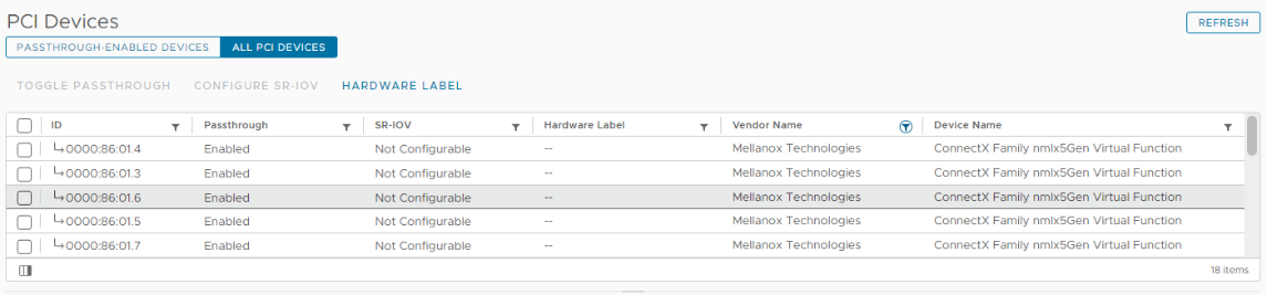
Figure 6: Virtual Functions in vSphere
Follow your server vendor’s documentation on how to enable SR-IOV at the BIOS/UEFI level, here is an example on setting Global SR-IOV to enabled through Dell’s iDRAC:
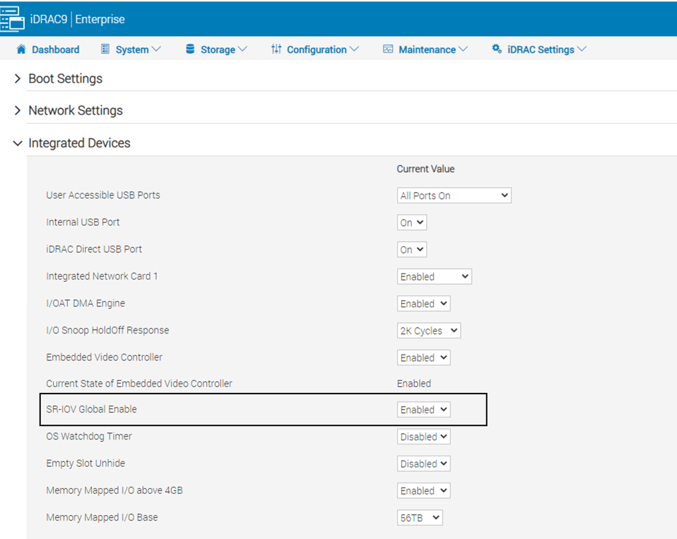
Figure 7: Enable Global SRIOV in BIOS
Advanced GPU Technologies: NVIDIA GPUDirect RDMA, NVLink, and NVSwitch
The combination of GPUDirect RDMA, NVLINK, and NVSwitch plays a pivotal role in enhancing GenAI. GPUDirect RDMA enables direct GPU-to-GPU memory access through network devices, efficiently reducing latency and amplifying data sharing capabilities. NVLINK serves as a high-speed, low-latency bridge between GPUs, particularly valuable in managing extensive datasets. NVSwitch orchestrates communication in multi-GPU configurations, offering a crucial foundation for scaling GenAI.
GPUDirect RDMA on VMware vSphere
GPUDirect on VMware vSphere works by leveraging NVIDIA vGPU technology and RDMA-capable network adapters like the NVIDIA ConnectX-6. For VMs Access Control Services (ACS) relax VMX settings as well as NUMA affinity or device groups must be configured, to enable peer-to-peer communication between the PCIe devices on the same Root Complex, at the time of writing, Device groups are yet supported for Tanzu Kubernetes Grid so proper NUMA and Root complex alignment cannot be assured, Device groups are expected to be available via VM classes on a future vSphere 8 release. Refer to the following links To configure ACS, NUMA affinity, or device groups, see Deploy an AI-Ready Enterprise Platform on vSphere 7 Update 2, vSphere 8 Expands Machine Learning Support: Device Groups for NVIDIA GPUs and NICs.
VMware Environment Preparation
To properly prepare VMware environments, plan the following items:
- Assessment and Planning: Begin by assessing your organization's requirements, including computing resources, storage, networking, and application needs. Plan the virtual infrastructure, accordingly, considering factors such as scalability, redundancy, and disaster recovery. It is crucial to understand the workload demands and design a flexible architecture to accommodate future growth.
- Hardware Selection and Compatibility: Choose hardware components that are compatible with VMware's virtualization platform. Ensure that the server hardware, storage devices, and networking equipment are on VMware's Hardware Compatibility List (HCL) to guarantee smooth operations and optimal performance.
- Networking Setup: Create virtual networks and VLANs to segregate traffic and enhance security. Consider using VMware NSX-T provided by VMware Cloud Foundation or VMware's distributed switches for more streamlined network management and monitoring. Implement proper firewall configurations, configure network security policies, and isolate sensitive workloads as required.
- Backup and Disaster Recovery: Establish a robust backup and disaster recovery strategy to protect critical data and ensure business continuity. Consider utilizing VMware's Data Protection tools or integrate with third-party backup solutions.
- Performance Monitoring and Optimization: Consider utilizing tools like vCenter Server and VMware Aria Operations to identify performance bottlenecks and make informed decisions to optimize resource utilization and maintain optimal performance.
There are multiple options of preparing the VMware environment, here we provide two options to configure the VMware environment with or without VMware Cloud Foundation. VMware Cloud Foundation Environment Preparation summarizes the high-level steps of preparing the VMware environment with VMware Cloud Foundation; in any cases that VMware Cloud Foundation environment could not be configured, you can follow the steps in vSphere Environment Preparation to prepare the VMware Environment.
Option 1. VMware Cloud Foundation Environment Preparation
- Familiarize with the VMware Cloud Foundation design and concepts. The VMware Cloud Foundation Design Guide contains requirements and recommendations for the design of each component of the SDDC.
- Ensure all servers and network switches are supported and meet VMware Cloud Foundation requirements by consulting the VMware Compatibility Guide.
- Based on the chosen design options, configure the network and services (DNS, DHCP, NTP), then complete the VMware Cloud Foundation Planning and Preparation Workbook.
- Prepare the ESXi hosts for VMware Cloud Foundation by installing the appropriate ESXi version and configuring the systems. Details on how to install and configure the systems are found in the Prepare ESXi Hosts for VMware Cloud Foundation in the VMware Cloud Foundation Deployment Guide.
- Deploy the VMware Cloud Foundation management domain by deploying the VMware Cloud Builder and using the VMware Cloud Foundation Planning and Preparation Workbook. Cloud builder creates the management cluster, deploys the SDDC manager, then creates the vCenter and NSX-T for the management domain. More detail about the process can be found in the VMware Cloud Foundation Deployment Guide.
- Once the VMware Cloud Foundation management domain deployment is complete, use the SDDC manager to add additional hosts and created additional VI workload domain. More detail about the process of adding and creating VI workload domain can be found in the VMware Cloud Foundation Administration Guide.
Option 2. Standalone vSphere Environment Preparation
- VMware vCenter Server 8.0 Update 1b or later is configured to manage the ESXi servers. We recommend running it as a VM on a separate host to the above host. For the vCenter Server installation procedures and details, see About vCenter Server Installation and Setup.
- VMware vSphere Hypervisor 8.0 Update 1 installed on each of the servers. For the Hypervisor installation procedures and details, see About VMware ESXi Installation and Setup.
- Furthermore, About VMware vCenter Server and Host Management provides information about vCenter and ESXi server management and configuration.
- Also, we recommend using VMware vSAN as the first tier storage for VM placement, for more information, see About vSAN Planning and Deployment.
After vSphere Cluster is configured, make sure vSphere Availability and vSphere DRS with fully automated setting are enabled on the target vSphere Cluster.
Software Configuration
Software Configuration Considerations
GPU Configuration in vSphere: vGPU or Passthrough
In a vSphere environment, using GPUs via passthrough (either DirectPath I/O or Dynamic DirectPath I/O) provides VMs with exclusive access to a physical GPU, resulting in maximum performance and predictable latency. However, this method is not efficient in scenarios with lighter GPU workloads, as any unused GPU capacity goes wasted. vGPU technologies (Time Sliced or MIG) on the other hand, allow multiple VMs to share GPU resources. This promotes optimal utilization and provides flexibility in resource allocation. MIG takes a middle ground by partitioning a GPU into isolated instances, which offers predictable performance closer to passthrough with full isolation while allowing for better hardware utilization like vGPU with Time Sliced mode. However, MIG is available for ampere or newer NVIDIA GPU Architectures, and configurations can be limited based on the specific partitioning options available. For this guide we decided to use vGPU with Time Sliced mode but any other options such as MIG or passthrough could work as well.
The following table provides benefits and tradeoffs of each GPU technology available with VMware vSphere:
Table 9: Benefits and Limitations of GPU Technology with VMware vSphere
|
|
vGPU Time Sliced |
vGPU MIG |
Dynamic DirectPath /IO |
DirectPath I/O |
|
Tanzu VM Class Supported |
Yes |
Yes |
Yes |
No |
|
Fractional GPUs |
Yes |
Yes |
No |
No |
|
Suspend and Resume |
Yes |
Yes |
No |
No |
|
Snapshot |
Yes |
Yes |
No |
No |
|
Host Maintenance Mode |
vMotion |
vMotion |
Cold Migration |
VM Shutdown |
|
Load Balance DRS |
No |
No |
No |
No |
|
Initial Placement DRS |
Yes |
Yes |
Yes |
No |
|
vMotion |
Yes |
Yes |
Yes |
No |
|
Failover HA |
Yes |
Yes |
Yes |
No |
Network Adapter Configuration Consideration
The adapter type to be used in VMware stacks can be selected as follows with virtualization features and performance.
Table 10: Network Adapter Configuration
|
Category |
Paravirtual |
Passthrough |
|||
|
Network adapter type |
VMXNET3 |
PVRDMA |
DirectPath IO |
Dynamic DirectPath IO |
SRIOV |
|
vMotion/ Snapshot/Suspend & Resume supported? |
Yes |
Yes |
No |
No |
No |
|
HA/DRS supported? |
Yes |
Yes |
No |
Yes* (DRS initial placement in vSphere 7) |
Yes* (DRS initial placement in vSphere 8U2) |
|
Virtual Distributed Switch required? |
Yes |
Yes |
No |
No |
Yes |
|
Multi-VMs sharing? |
Yes |
Yes |
No. Exclusive to 1 VM |
Yes. But exclusive to 1 VM once powered on. |
Yes |
|
RDMA capability |
No. TCP only |
RoCE only |
IB or RoCE |
IB or RoCE |
IB or RoCE |
|
Tanzu VM Class supported? |
Yes |
No |
No |
Yes |
Yes |
Considering the performance requirement for GenAI use case and resource utilization, we choose to enable SRIOV on the NIC to be used in the workload network. Through VF-level bandwidth specification, SRIOV ensures allocated bandwidths for workloads or VMs, thus meeting the SLA commitments of specific tasks and avoiding bandwidth monopolization. More related works can be found in Virtualizing HPC on VMware vSphere: Choosing a Best Method for RDMA HCA/NIC Deployment for MPI Workloads.
Install VMware Installation Bundles
vSphere Lifecycle Manager (vLCM) is introduced since vSphere 7 and can improve lifecycle management on a cluster. It can integrate the NVAIE vGPU driver and Mellanox firmware tools with the vSphere base image to enforce consistency across the ESXi hosts. Here is the flowchart for this step:

Figure 8: Flowchart to Install VIB of NVAIE and MFT
The NVAIE driver is available at the NVIDIA Licensing Portal, part of the NVIDIA APPLICATION HUB. Go to the SOFTWARE DOWNLOADS option in the left menu, or go directly to https://ui.licensing.nvidia.com/software if logged in. For ML workloads, choose the NVAIE from the product family. The NVAIE product family provides vGPU capability for compute (ML/AI) workload.
Note: The vGPU family is for vGPU functionality for the VDI workload. Next extract the "NVAIE-AI-Enterprise-vSphere-xxx.zip" package. Then, navigate to the "Host Driver" directory and locate the "NVD-AIE-xxx.zip" file. This file contains the vGPU host driver that needs to be imported to vLCM.
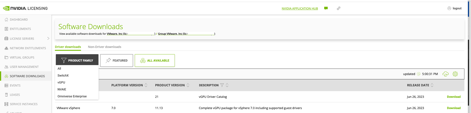
Figure 9: Download the NVAIE Package from NVIDIA
Mellanox Firmware Tools (MFT) consists of MFT & NMST components. Download them for VMware vSphere 8 update 1 from this link: https://network.nvidia.com/products/adapter-software/firmware-tools/. We selected the 4.24 version in the archive versions since it is compatible with the VMware vSphere 8 update 1 used in VMware Cloud Foundation 5.0.

Both downloaded MFT packages must be unpacked, then upload “NVD-AIE-xxx.zip”, “Mellanox-MFT-Tools_xxx.zip”, and “Mellanox-NATIVE-NMST_xxx.zip” files to vSphere Lifecycle Manager by opening the vSphere client menu (click on the three lines in the top left corner next to vSphere Client) select Lifecycle Manager, select ACTIONS, Import Updates.


Figure 10: Import VIBs with vLCM
Next, we used vSphere Lifecycle Manager Baselines to create a host extension baseline by clicking the targeted Cluster > Updates > Hosts > Baselines > New Baseline > Type name, description, and select Extension > Find and Select “NVAIE”, “MFT” and “NMST” as extension > Finish.
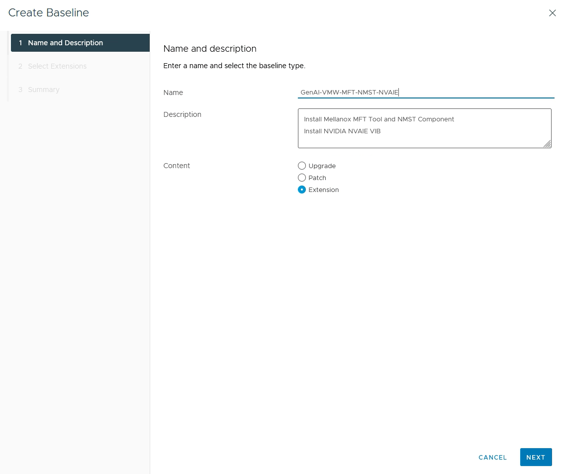
Figure 11: Create a Host Extension Baseline

Figure 12: Summary of Baseline Extension with NVAIE and MFT
Next we remediated the cluster by clicking the targeted Cluster > Updates > Hosts > Baselines > select the baseline created > REMEDIATE. Then vLCM will put each host into maintenance mode, install VIBs, and reboot one by one.
Alternatively, we can manually put each host into maintenance mode and SSH into each host, then install the above three VIBs by running the following commands and reboot individually:
esxcli software vib install -d /PATH_TO/“NVD-AIE-xxx.zip”

esxcli software vib install -d /PATH_TO/"Mellanox-NATIVE-NMST-xxx.zip"

esxcli software vib install -d /PATH_TO/"Mellanox-MFT-Tools-xxx.zip"
Configure vGPU
After the NVAIE vGPU Manager VIB is installed, open an SSH session to each ESXi host to verify that the NVIDIA vGPU Manager is available and can detect the GPUs on the system:

Figure 13: Verify vGPU is Detected in ESXi
The GPU(s) of each ESXi host could be configured based on the required GPU technology, either vGPU or MIG. To configure GPU as dynamic DirectPath I/O, refer to our existing documentation.
Here are the steps to configure vGPU on each ESXi host in the vSphere client.
- Log in to vSphere Client and navigate to vCenter > Datacenter > Cluster > Host > Configure > Graphics and click on HOST GRAPHICS.
- Under the Host Graphics click Edit and choose Shared Direct and Spread VMs across GPUs.
- After these settings applied, click on tab GRAPHIC DEVICES, choose one GPU listed below and click EDIT…, ensure that Restart X.Org server is checked and Shared Direct is selected, then click OK.
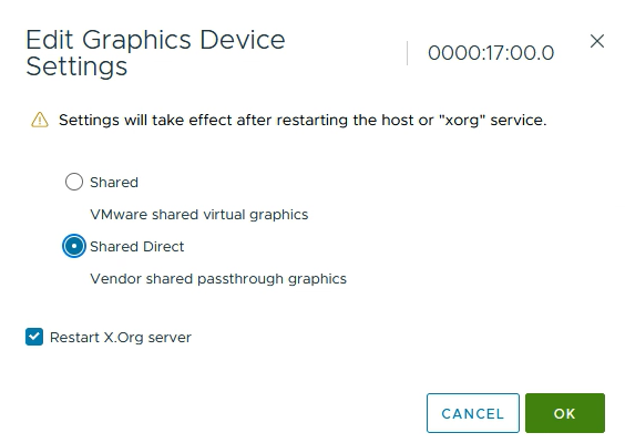
Figure 14: Configure vGPU in vSphere Client
- Confirm the setting has been set:

Figure 15: Verify vGPU Status in vSphere Client
Configure SRIOV and PFC on Mellanox NICs
After MFT is installed, we will employ MFT to enable SR-IOV on NIC firmware and enable flow control and SR-IOV parameters on RoCE ports of each host.
Activate SR-IOV and Priority Flow Control (PFC) using these commands, then reboot the host:
/opt/mellanox/bin/mlxconfig -d mt4125_pciconf0 -y set SRIOV_EN=1 NUM_OF_VFS=16

esxcli system module parameters set -m nmlx5_core -p "pfctx=0x08 pfcrx=0x08 trust_state=2 max_vfs=8,7 ecn=1"

reboot
In the first command, NUM_OF_VFS=16 creates VFs on the firmware.
In the second command, max_vfs=8,7 configures VFs on each of the two ports, and pfctx=0x08 pfcrx=0x08 ecn=1 explicitly enables the setting of Priority Flow Control (PFC) and Explicit Congestion Notification (ECN) on RoCE ports.
If a Mellanox VPI HCA is used in your environment, the LINK_TYPE parameter is required to set the transport mode as IB or RoCE. This can be determined by running:
/opt/mellanox/bin/mlxfwmanager -d $Your_Device_PCIE_IDAnd then check whether the “Description” row of the device contains “VPI”. For more about how to configure SRIOV RoCE or IB on NIC/HCA, refer to RoCE SR-IOV Setup and Performance Study on vSphere 7.x and InfiniBand SR-IOV Setup and Performance Study on vSphere 7.x.
Enabling vSphere with Tanzu
There are two options to enable vSphere with Tanzu. You can either enable vSphere with Tanzu with VMware Cloud Foundation or Service Installer. If you have VMware Cloud Foundation deployed, it is highly recommended to enable vSphere with Tanzu service by following the steps in Enabling vSphere with Tanzu with VMware Cloud Foundation. Otherwise, follow the steps in Enabling vSphere with Tanzu with Service Installer.
Option 1. Enabling vSphere with Tanzu with VMware Cloud Foundation
In VMware Cloud Foundation deployments, it is recommended to follow the Workload Management solution workflow built into SDDC Manager to streamline the enabling of Workload Control Plane (WCP) over NSX-T based networks. This solution integration reliably and efficiently manages the complete lifecycle management of all VMware Cloud Foundation components within its framework that results in consistent operations across all deployments.
The list below summarizes the high-level steps required to enable VMware Cloud Foundation with Tanzu Services using Workload Management solution. Refer to VMware Cloud Foundation for VMware Tanzu in VMware Cloud Foundation Administration Guide for more information.
- Sizing compute and storage resources for Workload Management
- Create a Subscribed Content library
- Enable Workload Management
- View Workload Management cluster details
- Update Workload Management license
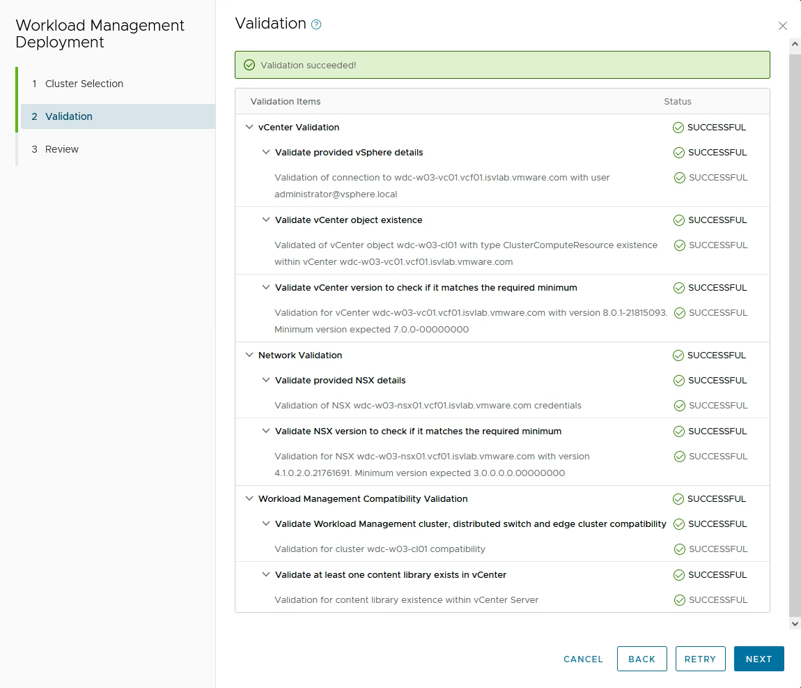
Figure 16: SDDC Manager Validating Tanzu Prerequisites
After you follow the Workload Management solution workflow to enable WCP, you may skip to the Deploy Tanzu Kubernetes Workload Cluster section below.
For non-VMware Cloud Foundation environments, you may use Service Installer for VMware Tanzu to enable WCP.
Option 2. Enabling vSphere with Tanzu with Service Installer
Service Installer for VMware Tanzu Overview
Service Installer automates the deployment of the reference designs for Tanzu for Kubernetes Operations on several cloud platforms, including vSphere with Tanzu backed by VDS. Automation with Service Installer for VMware Tanzu simplifies the deployment of a Kubernetes environment. It uses best practices for deploying and configuring the required Tanzu for Kubernetes Operations components such as Tanzu Kubernetes Grid, Tanzu Mission Control, Tanzu Service Mesh, Tanzu Observability, NSX Advanced Load Balancer, and a set of shared services including Harbor, Prometheus, Grafana, Valero, Cert Manager, Contour, and Fluentbit. For more information, refer to the Service Installer for VMware Tanzu documentation.
Installing with Service Installer
Before you deploy Tanzu for Kubernetes Operations using Service Installer for VMware Tanzu, refer to the “Prerequisites” section in Deploying VMware Tanzu for Kubernetes Operations on vSphere with Tanzu and vSphere Distributed Switch Using Service Installer for VMware Tanzu. Follow the documentation to download and deploy the Service Installer. Proceed to follow the procedure Deploy Tanzu for Kubernetes Operations and choose the deployment type “Enable Workload Control Plane”, configure and generate a JSON file, and use the arcas CLI to initiate WCP deployment. To verify if the deployment is successful, go to “Workload Management” and select the “Supervisors” tab in vSphere Client to confirm if the “Config Status” and “Host Config Status” are both in “Running” state.
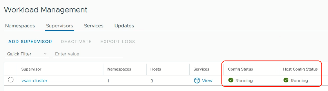
Figure 17: vSphere with Tanzu Supervisor Cluster is Up
Deploying Tanzu Kubernetes Workload Cluster
Before deploying a workload cluster, you need to follow the instructions below to create a custom VM class with the vGPU profile.
Creating VM Class
- Log on to the vCenter Server using the vSphere Client.
- Select Workload Management > Services > VM Service > Manage.
- Select VM Classes > Create VM Class.
- Specify the VM settings as shown below and select NEXT:
![]()

Figure 18: Creating the VM Class
- Select ADD PCI DEVICE > NVIDIA vGPU, choose the hardware model that you have, and populate the remaining settings as shown below:

Figure 19: Adding vGPU and NIC VF to VM Class
- Select NEXT and FINISH to finish creating the custom VM class.
Deploying Tanzu Kubernetes Workload Cluster
After the custom VM class is created and WCP is enabled, there are two options to provision a Tanzu Kubernetes workload cluster. If you have custom configurations such as volume mounts in workload cluster nodes, you can follow the vSphere product documentation Provisioning TKG Clusters on Supervisor, use the kubectl commands and the YAML file to provision a workload cluster.
Alternatively, if Service Installer is used and there is no custom TKC configuration requirement, you can repeat the same steps in the Service Installer but choose the deployment type “Namespace and Workload Cluster”. As you specify parameters to generate a JSON file, make sure to choose the custom VM class that was created with vGPU profile for "WORKER VM CLASS". Once a JSON file is created, use the arcas CLI again to initiate the creation of a Tanzu Kubernetes workload cluster.
To test the connectivity to the workload cluster, refer to the vSphere documentation Workflow for Provisioning TKG Clusters on Supervisor Using Kubectl to download and install the Kubernetes CLI tools for vSphere, then use the kubectl commands to monitor the cluster provisioning, and log into the workload cluster to check its resources.
Deploying NVIDIA GPU Operator
The NVIDIA GPU Operator uses the operator framework within Kubernetes to automate the management of all NVIDIA software components needed to provision GPU. These components include the NVIDIA drivers (to enable CUDA), Kubernetes device plugin for GPUs, the NVIDIA Container Toolkit, automatic node labelling using GFD, DCGM based monitoring and others.
The GPU Operator allows administrators of Kubernetes clusters to manage GPU nodes just like CPU nodes in the cluster. Instead of provisioning a special OS image for GPU nodes, administrators can rely on a standard OS image for both CPU and GPU nodes and then rely on the GPU Operator to provision the required software components for GPUs.
The GPU Operator also enables GPUDirect RDMA; a technology in NVIDIA GPUs that enables direct data exchange between GPUs and a third-party peer device using PCI Express. The third-party devices could be network interfaces such as NVIDIA ConnectX SmartNICs or BlueField DPUs amongst others.

Figure 20: GPUDirect RDMA Technology
To support GPUDirect RDMA, a userspace CUDA APIs and kernel mode drivers are required. Starting with CUDA 11.4 and R470 drivers, a new kernel module nvidia-peermem is included in the standard NVIDIA driver installers with ".run" extensions. The kernel module provides Mellanox InfiniBand and RoCE adapters direct peer-to-peer read and write access to the GPU’s memory.
In conjunction with the Network Operator, the GPU Operator can be used to set up the networking related components such as Mellanox drivers, nvidia-peermem and Kubernetes device plugins to enable workloads to take advantage of GPUDirect RDMA.
GPUDirect has multiple requirements:
- MOFED Drivers need to be installed: for Tanzu workloads, these drivers will be installed by NVIDIA’s Network Operator. For VMs, refer to NVIDIA’s documentation for details on the installation process.
- Make sure the Network interface controller and the NVIDIA GPU are in the same PCIe I/O root complex, you can leverage vSphere device groups with VMs to accomplish this, for Tanzu Worker nodes this is yet supported.
- Enable the following VMX advanced settings:
We need to install this GPU Operator on each TKC that will be used for GPU-enabled workloads. We will proceed to install it on the cluster that we previously created.
See the following high-level overview of the installation process, refer to the NVIDIA GPU Operator Step-by-Step Installation Process for a complete step-by-step installation:
- Create a namespace.
- Configure vGPU license via ConfigMap.
- Create a secret to pull from the NGC repository.
- Set up NVAIE Helm repository.
- Install GPU Operator via Helm.
- Verify the installation of GPUDirect with RDMA.
Deploying NVIDIA Network Operator
NVIDIA Network Operator leverages Kubernetes CRDs and Operator SDK to manage networking related components, in order to enable fast networking, RDMA and GPUDirect for workloads in a Kubernetes cluster. The Network Operator works in conjunction with the GPU Operator to enable GPUDirect RDMA on compatible systems. The goal of the Network Operator is to manage the networking related components, while enabling execution of RDMA and GPUDirect RDMA workloads in a Kubernetes cluster. This includes:
- NVIDIA Networking drivers to enable advanced features.
- Kubernetes device plugins to provide hardware resources required for a fast network.
- Kubernetes secondary network components for network intensive workloads.
The NVIDIA Network Operator can be deployed in different modes, for this guide we will deploy a network operator with Host Device Network, this deployment includes:
- SR-IOV device plugin, single SR-IOV resource pool
- Secondary network
- Mutlus CNI
- Container networking-plugins CNI plugins
- Whereabouts IPAM CNI plugin
In this mode, the Network Operator could be deployed on virtualized deployments as well. It supports both Ethernet and InfiniBand modes. From the Network Operator perspective, there is no difference between the deployment procedures. To work on a VM the PCI passthrough must be configured for SR-IOV devices. The Network Operator works both with VF and Physical Function (PF) inside the VMs or Tanzu Worker nodes.
High level overview of installation process, refer to the
NVIDIA Network Operator Step-by-Step Installation Process
for a complete step-by-step installation:
- Create a namespace.
- Create a secret to pull from NGC repository.
- Create a values.yaml file.
- Install the Network Operator via Helm.
- Create Hostdev custom resource.
- Verify the nvidia-peermem-ctr container.
Refer to Appendix for Virtual Function Verification and Testing Process and Verifying the Installation of GPUDirect with RDMA.
Creating VM Service for Single Node Learning
In the LLM training use case, you can provision a single node VM using VM service as follows:
- Repeat the Creating VM Class procedure in the previous section and specify the desired settings for your VM. For example, you may want to configure two or more for the parameter “Number of vGPUs”. In this solution, we created the VM class named single-vm-gpu in Table 5.
- Follow the instructions here to create a namespace on the Supervisor Cluster, and configure the Permissions, Storage, Capacity, and Usage.
- Follow the instructions here to create a local content library for VM Service.
- Download ubuntu-20.04-vgpu.ova from our GitHub repo and import it to the local content library.
for i in `seq 1 9`; do wget https://raw.githubusercontent.com/vmware-ai-labs/VMware-generative-ai-reference-architecture/main/vSphere-and-TKG-config-files/TKGs/ubuntu-template/ubuntu-20.04-vgpu.zip.00$i; done for i in `seq 10 22`; do wget https://raw.githubusercontent.com/vmware-ai-labs/VMware-generative-ai-reference-architecture/main/vSphere-and-TKG-config-files/TKGs/ubuntu-template/ubuntu-20.04-vgpu.zip.0$i; done cat ubuntu-20.04-vgpu.zip.0* > ubuntu-20.04-vgpu.zip unzip ubuntu-20.04-vgpu.zip - Follow the instructions here to associate the local content library with the namespace created in step 2.
- Follow the instructions here to associate the custom VM class with the namespace created in step 2.
- Proceed to provision a single node VM for learning use case by using the custom VM class and following the instructions in Deploying a Stand-Alone VM in vSphere with Tanzu. In this solution, we created the single node VM by using this YAML file.
- Access the single node VM via SSH after getting the IP address. And follow the instructions in NVIDIA vGPU Driver Step-by-Step Installation Process to install the NVIDIA vGPU Driver.
kubectl describe vmservice vm-basic-ssh | grep Ip
Running LLM Tasks on vSphere with Tanzu Kubernetes
Overview
After you have deployed and configured vSphere and Tanzu Kubernetes infrastructures according to the Deployment and Configuration section, your environment is ready to run different types of tasks related to LLMs and GenAI. For that purpose, we provide two working examples of the most frequent used ones: LLM fine-tuning and LLM inference. The intention of the working examples is twofold: On the one hand, it provides you with a procedure to verify the reference architecture deployment works appropriately; on the other hand, the examples show how two working examples perform those essential tasks in the LLM development lifecycle.
Task 1: LLM Fine-tuning
Introduction to Fine-tuning Task
In this section, we present a fine-tuning task example (including the instructions to set up a Python environment and the LLM fine-tuning code) to show you how to use the VMware GenAI reference architecture to perform one of the most computing-intensive tasks in the LLM development lifecycle.
The open-source community keeps releasing LLMs which you can retrieve from the popular Hugging Face Hub. Examples of these models are Falcon-40B and Falcon-7B, which rank close to the top of the Open LLM Leaderboard at the time of this writing. The Falcon pre-trained models belong to the foundational type of LLMs, which can get further trained via fine-tuning to improve their capabilities to serve specific tasks and knowledge domains.
Using LoRA and RLHF
To simplify the LLM fine-tune process, we rely on parameter-efficient fine-tuning (PEFT) methods which minimize the computational resources and time required for fine-tuning. One popular technique for parameter-efficient fine-tuning is Low-Rank Adaptation (LoRA). LoRA freezes the pre-trained model weights and injects trainable rank decomposition matrices into each layer of the Transformer architecture, reducing the number of trainable parameters for downstream tasks. Compared to GPT-3 175B fine-tuned with Adam, LoRA can reduce the number of trainable parameters by 10,000 times and the GPU memory requirement by three times. We utilize the LoRA implementation included the Hugging Face PEFT library.
Another common element of the LLM fine-tuning process is Reinforcement Learning from Human Feedback (RLHF) which enables LLMs to learn from human expertise and domain-specific knowledge, leading to improved performance on specific tasks. The iterative nature of RLHF allows the model to adapt and refine its behavior based on evaluators' feedback, resulting in more accurate and contextually appropriate responses. In our example we use Hugging Face supervised fine-tuning (or SFT for short) which implements RLHF based on a series of prompt completion examples provided by the Guanaco dataset which we use to teach the Falcon models to answer questions asked by humans in a conversational manner.
Accessing the Python Code Repository
As a complementary resource we have published a GitHub repo that provides the Python code required to fine-tune Falcon-7B using a single A100 (40G) GPU and Falcon-40B on two of those GPUs. As previously mentioned, the scripts leverage the Hugging Face's implementation of LoRA (part of the PEFT package) and the bits and bytes library (by Tim Dettmers) to load the models using 16-bit or 8-bit quantization.
The Python code is presented as a Jupyter notebook where we explain all the steps involved in the LLM fine-tuning process, which can be broken down into the following sections:
- How to stack the execution of Hugging Face libraries (PEFT/LoRA, SFT trainer) to load the Falcon LLMs and the instruction datasets required for the fine-tuning task.
- A description of the list of parameters required for LLMs loading and training.
- The configuration of LangChain pipelines to use the fine-tuned model for prompt completion tasks.
Requirements
A VM with a fresh installation of Ubuntu Desktop 22.04 with the following requirements, or this VM can be created by vSphere with Tanzu VM Service. For more details, refer to the Creating VM Service for Single Node Learning section of this document.
- One or two NVIDIA A100 (40GB) GPUs attached either as vGPU or DirectPath I/O devices. You can use other NVIDIA GPUs with less memory but that might limit the size of the model you will be able to load.
- 64GB of CPU RAM
- 16 vCPU
- 500GB of disk storage. Notice that the more model checkpoints you decide to keep, the more storage space you will need.
- Internet connectivity to download software packages, LLM models and datasets
Ensure the following Advanced Configuration Parameters are configured in the VM:
- pciPassthru.64bitMMIOSizeGB=512
- pciPassthru.use64bitMMIO=TRUE
If the VM is configured with vGPU(s), make sure the following Advanced Configuration Parameters are also configured to enable Unified Memory for NVIDIA GPU:
- pciPassthru[vGPU-ID].cfg.enable_uvm=1
For example, if there are four vGPUs configured in the VM, these parameters should be set:
- pciPassthru0.cfg.enable_uvm=1
- pciPassthru1.cfg.enable_uvm=1
- pciPassthru2.cfg.enable_uvm=1
- pciPassthru3.cfg.enable_uvm=1
Python Environment Setup
Installing NVIDIA Grid GPU Drivers and CUDA 11.8
First refer to NVIDIA vGPU Driver Step-by-Step Installation Process for Ubuntu 22.04 desktop.
Next, you need to download the CUDA 11.8 toolkit and install it. Perform the following steps:
# Download the binaries for Ubuntu 22.04

wget https://developer.download.nvidia.com/compute/cuda/11.8.0/local_installers/cuda_11.8.0_520.61.05_linux.run

# Execute the run file

sudo sh cuda_11.8.0_520.61.05_linux.run
The CLI command will start a text-based dialog interface. You might get a warning like this:

Using the keyboard arrows, select Continue and hit Enter. Next, you need to accept the EULA to continue.

Then use the keyboard to move down the screen and using the space bar, deselect the Driver, the CUDA Demo Suite and the CUDA documentation. Then move to the Install option and hit Enter as shown next.

After the installer finishes, add a new line to /etc/ld.so.conf with the /usr/local/cuda-11.8/lib64 entry. Then execute the following command:
# Add new line to /etc/ld.so.conf with the /usr/local/cuda-11.8/lib64, then execute the following command
echo "/usr/local/cuda-11.8/lib64" | sudo tee -a /etc/ld.so.conf
sudo ldconfig
CUDA will get installed under /usr/local
ls /usr/local

# cuda  cuda-11.8  etc  games  include  lib  man  sbin  share  src
Miniconda Installation Steps
We recommend the use of Miniconda as the Python package management system over the default distributions embedded in the OS. Perform the following shell commands to set up a Python environment.
## Installing Miniconda

# Downloading the latest Miniconda installer for Linux.

wget -nc https://repo.anaconda.com/miniconda/Miniconda3-latest-Linux-x86_64.sh

# Perform a Miniconda silent installation

bash ./Miniconda3-latest-Linux-x86_64.sh -b -p $HOME/miniconda

# Add Conda activation, assuming you use bash as SHELL

eval "$($HOME/miniconda/bin/conda shell.bash hook)"

# With this activated shell, install conda's shell functions

conda init
Python Virtual Environment Setup
Clone the git repository for the Jupyter notebook that contains the LLM fine-tune code:
## Cloning the git repo

# Verify git is installed

git –version

# If git is not installed, install it with these two commands

sudo apt update

sudo apt install git

# Clone the git repo containing the fine-tune Jupyter notebook

git clone https://github.com/vmware-ai-labs/VMware-generative-ai-reference-architecture.git

# Enter the repo’s root directory

cd VMware-generative-ai-reference-architecture/LLM-fine-tuning-example/
Then run the following commands to create a Conda virtual environment:
## Setting-up the virtual env for LLM tasks
# Create the conda virtual env u
conda env create -f llm-env.yaml
# Create the virtual env using a conda dependency specification
#  - The package versions in the YAML file have been tested by our experiments
conda activate llm-env
# OPTIONAL: login to wandb.ai using the CLI
#   - The wandb.ai dashboard allows you to follow the training process online.
#   - You'll need free account and an API key
#   - See details at https://docs.wandb.ai/quickstart
wandb login
# Start Jupyter-lab session
jupyter-lab --ip  VM_IP
Running the Falcon LLM Fine-tuning Job
Next, your web browser will show a JupyterLab session like the one shown next. Double click on the Notebook-Falcon-finetune.ipynb file to open the notebook and get ready to go over the Falcon LLM fine-tune process. Notice that we switched the JupyterLab theme to dark mode from the Settings menu.
![]()

Figure 21: Launch Jupyter-Lab
After the notebook is open, you can follow the notebook annotations that explain the LLM fine-tune process and the role of each component of it.

Figure 22: Open Fine-tuning Notebook
Running all the cells in the Notebook-Falcon-finetune.ipynb script gives you all you need to verify the whole GenAI stack is properly configured and operational. Here is the list of things to watch for to verify the system works as expected.
Monitoring the Training Process
Cell #7 from the notebook runs the training loop. If you keep the setting that makes WandB the logging tool, you can follow the evolution of the training job online by using the random URL (hosted at wandb.ai) provided in the cell’s output. Here is the list of things to watch:
- You need to verify is that the validation loss metric decreases as the number of training steps increases. It should look like this:

Figure 23: Evaluation Loss Metric
- When training the Falcon 40B LLM (loaded in 8-bits) on 2 x A100 (40GB) GPUs, the GPU memory and process would look like this (blue line represents GPU:0 and the orange line represents GPU:1):


Figure 24: GPU Memory Demonstration
At the end of the training process, WandB will provide a run summary as shown below, which demonstrates a run of 120 training steps. This is also part of cell #7’s output.

Figure 25: Validation Running Summary
Finding the Best Model Checkpoints
After the training (fine-tune) process is over, the trainer will save the best and the last checkpoints at the results directory so you should see couple of sub-directories named after the checkpoint number they contain. For instance, after 120 training steps, cell #7 could output:
Best check point path is ./results/checkpoint-120Running Prompt Completions Locally
The last test is about using the best LLM checkpoint to run several prompt completions. Cell #9 submits a prompt to the LLM to explain a fundamental scientific concept. The LLM acts as a knowledge base.
prompt = f"""

The following is a friendly conversation between a Human and an Assistant. The Assistant is

concise and explains concepts in an accessible manner.

Human:  Explain the concept of magnetism.

Assistant:

""".strip()

completion = chat_llm(prompt)

print(f"Assistant:\n{completion}")

Assistant:

Magnetism is one of the four fundamental forces that governs our universe, along with gravity, electromagnetism, and the strong nuclear force. It is responsible for many phenomena we observe on Earth, such as how magnets attract or repel each other, why compass needles point north, and even how electricity flows through wires. In short, it is what makes things stick together!
In addition, cell #10 runs a one-shot prompt asking the LLM to function as a reasoning engine and a coding assistant to solve a basic math problem and write a Python function to calculate the solution:
prompt = """

Human: At a store, shoes cost shoe_cost pair and socks cost sock_cost per pair.

If a customer buys shoe_p pairs of shoes and  sock_p pairs of socks, what is the total cost of the purchase?

Write a Python function that returns the answer.

Assistant:

def store_cost(shoe_cost, shoe_p, sock_cost, sock_p):

  return (shoe_cost * shoe_p) + (sock_cost * sock_p)

Human: At the cinema, tickets for adults cost adult_fee and tickets for children cost child_fee

If a family with num_adult adults and num_child children go to the movies, what is the total cost for that family?

Write a Python function that returns the answer.

Assistant:

""".strip()

completion = chat_llm(prompt)

print(f"Assistant:\n{completion}")

Assistant:

def movie_cost(adult_fee, child_fee, num_adult, num_child):

    return (num_adult * adult_fee) + (num_child * child_fee)
Task 2: LLM Inference
Introduction to Ray and vLLM
Ray is an open-source distributed computing framework designed for modern data-driven and AI-powered applications. It offers benefits such as streamlining large-scale computations across distributed clusters.
Ray provides the following benefits:
- Scalability: Efficient scaling across clusters for handling large-scale computations.
- Flexibility: Supports both task and data parallelism to suit specific needs.
- Fault-tolerance: Ensures computation continues despite failures.
- Python-based: Developed in Python for ease of use.
- High-performance: Optimized for speed and efficiency.
- Resource management: Handles allocation and management of resources.
Ray’s working mechanism is as follows:
- Task submission: Users submit Python functions as tasks, defining computations and data dependencies.
- Distributed execution: Ray breaks down tasks into sub-tasks and schedules them across the cluster.
- Task synchronization: Manages data dependencies between tasks.
- Fault tolerance: Monitors execution and reschedules failed tasks.
- Resource management: Optimizes resource allocation based on workload.
In the Ray framework, there are two types of nodes:
- Ray head node: Acts as the central coordinator, managing the system state, scheduling tasks, and overseeing resource allocation.
- Ray worker nodes: Serves as computation units, executing tasks, and storing data.
The Ray head node maintains a global state that tracks all worker nodes, resources, and submitted tasks. Worker nodes execute the scheduled tasks, manage data, and synchronize data dependencies. One notable feature of Ray is its support for autoscaling, dynamically adjusting the number of worker nodes based on workload, which ensures efficient resource utilization and cost.
The Ray head and worker nodes’ configuration we use in this reference architecture is based on the following settings:
Table 11: Ray Head and Worker Node Configuration
|
Role |
Ray Version |
Docker Image |
Replicas |
CPU Allocation |
Memory Allocation |
#of GPU |
|
Head Node |
2.6.2 |
rayproject/ray:2.6.2-py310-gpu |
1 |
32 |
32GB |
1 |
|
Worker Nodes |
2.6.2 |
rayproject/ray:2.6.2-py310-gpu |
1-4 |
32 |
32GB |
1 per replica |
From the multiple functions available in Ray, we leverage Ray Serve (or Serve), a scalable model serving library for building online inference APIs.
In addition to Ray Serve, we use vLLM, an open-source library for fast LLM inference and serving. vLLM utilizes Paged Attention, a new attention algorithm that effectively manages attention keys and values. The vLLM authors claim it delivers up to 24x higher throughput than Hugging Face Transformers without requiring any model architecture changes. You can learn more about vLLM integration with Ray from the Anyscale article How continuous batching enables 23x throughput in LLM inference while reducing p50 latency.
Some of the key vLLM features are:
- Continuous batching of incoming requests.
- Seamless integration with LLMs available from the Hugging Face model repository.
- High throughput serving with various decoding algorithms, including parallel sampling, beam search, and more.
- Tensor parallelism support for distributed inference.
- Streaming outputs.
- OpenAI-compatible API server.
Setting up vLLM as a Ray Serve Application
To deploy vLLM as an API service on Ray Serve you need to follow a simple setup procedure. In our example, we deploy Ray on Tanzu Kubernetes using Kuberay, an open-source Kubernetes operator that simplifies the deployment and management of Ray applications on Kubernetes. It offers several key components:
KubeRay core: This is the official, fully maintained component of KubeRay that provides three custom resource definitions, RayCluster, RayJob, and RayService. These resources are designed to help you run a wide range of workloads with ease.
Here are the steps you must complete to run the vLLM service on Ray Serve. In our example vLLM serves the Falcon-7B model after pulling it from Hugging Face repository. All the scripts and YAML configuration files required to complete the setup are accessible from the vllm_examples GitHub repository. The scripts are based on the examples provided by the Anyscale team at continuous-batching-llm-inference.
Requirements:
- First you need to have a Kubernetes (K8s) cluster up and running.
- In our case, we rely on a TKC deployed following the instructions from the Deployment and Configuration section of this document.
- Ensure you have Helm installed in your environment.
Deploying a vLLM Service on Ray Serve
1. Set ClusterRoleBinding to run a privileged set of workloads. This will prevent a Kuberay operator installation failure.
kubectl create clusterrolebinding default-tkg-admin-privileged-binding --clusterrole=psp:vmware-system-privileged --group=system:authenticated2. Deploy Kuberay in your K8s cluster. More details at KubeRay Operator install docs.
# Add the Kuberay Helm repo.

helm repo add kuberay https://ray-project.github.io/kuberay-helm/

# Install both CRDs and KubeRay operator v0.6.0.

helm install kuberay-operator kuberay/kuberay-operator --version 0.6.0

# NAME: kuberay-operator

# LAST DEPLOYED: Thu Aug 10 12:41:07 2023

# NAMESPACE: kuberay

# STATUS: deployed

# REVISION: 1

# TEST SUITE: None

# Check the KubeRay operator pod in the `default` namespace.

kubectl get pods

# NAME                                READY   STATUS    RESTARTS   AGE

# kuberay-operator-6b68b5b49d-jppm7   1/1     Running   0          6m40s
3. Pull the Ray Serve manifest from GitHub and apply it.
# Pull the ray-service.vllm.yaml manifest (from this repo) from the raw URL

wget -L https://raw.githubusercontent.com/vmware-ai-labs/VMware-generative-ai-reference-architecture/main/LLM-serving-wt-vLLM-and-RayServe-example/ray-service.vllm.yaml

# Create a Ray Serve cluster using the manifest

kubectl apply -f ray-service.vllm.yaml

# Check the Ray pods got created

kubectl get pods

# The Ray cluster starts to create the head and worker pods

# NAME                                           READY   STATUS              RESTARTS   AGE

# kuberay-operator-6b68b5b49d-jppm7              1/1     Running             0          23m

# vllm-raycluster-c9wk4-head-gw958               0/1     ContainerCreating   0          67s

# vllm-raycluster-c9wk4-worker-gpu-group-wl7k2   0/1     Init:0/1            0          67s

# After several minutes, the Ray cluster should be up and running

kubectl get pods

# NAME                                           READY   STATUS    RESTARTS   AGE

# kuberay-operator-6b68b5b49d-jppm7              1/1     Running   0          39m

# vllm-raycluster-c9wk4-head-gw958               1/1     Running   0          17m

# vllm-raycluster-c9wk4-worker-gpu-group-wl7k2   1/1     Running   0          17m

# The vLLM service will get exposed as a LoadBalancer. In the next example

# The vLLM API service (vllm-serve-svc) gets exposed over http://172.29.214.16:8000.

# That is the URL you need to use to make prompt completion requests.

 kubectl get svc

# NAME                             TYPE           CLUSTER-IP       EXTERNAL-IP     PORT(S)

# kuberay-operator                 ClusterIP      10.105.14.110    <none>          8080/TCP

# vllm-head-svc                    LoadBalancer   10.100.208.111   172.29.214.17   10001...

# vllm-raycluster-c9wk4-head-svc   LoadBalancer   10.103.27.23     172.29.214.16   10001...

# vllm-serve-svc                   LoadBalancer   10.104.242.187   172.29.214.18   8000...
You can use the vllm-raycluster-c9wk4-head-svc IP on port 8265 (in our example is http://172.29.214.16:8265. Yours could change) to access the Ray cluster dashboard to monitor the Ray cluster status and activity. Notice ray-service.vllm.yaml manifest has the following section that defines the vLLM service deployment:
spec:
  serviceUnhealthySecondThreshold: 3600 # Health check threshold for service. Default value is 60.
  deploymentUnhealthySecondThreshold: 3600 # Deployments health check threshold. Default value 60.
  serveConfigV2: |
    applications:
      - name: vllm
        import_path: vllm_falcon_7b:deployment
        runtime_env:
          working_dir: "https://github.com/vecorro/vllm_examples/archive/refs/heads/main.zip"
          pip: ["vllm==0.1.3"]
Here are some remarks about the service definition:
- We increase
serviceUnhealthySecondThresholdanddeploymentUnhealthySecondThresholdto give Ray sufficient time to install vLLM on a virtual working environment. vLLM can take >15 minutes to install. working_diris set to the URL of the compressed version of the Github repo. Ray will use this URL to pull the Python code that implements the vLLM service.- We use vLLM 0.1.3 to create the Ray working environment.
import_pathis set to the propermodule:objectfor Ray Serve to get the service definition. In this case
themoduleis thevllm_falcon_7b.pyPython script anddeploymentis aserve.deployment.bind()
object type defined inside that script.
vLLM on Ray Serve Deployment Validation
Similar to the fine-tune example, we can validate our deployment by sending some prompt completion requests. The GitHub repo provides a script called gradio_webserver.py script to serve prompt completions from a web UI. The command line instructions to run it are as follows:
# Install gradio

pip install gradio

wget https://raw.githubusercontent.com/vmware-ai-labs/VMware-generative-ai-reference-architecture/main/LLM-serving-wt-vLLM-and-RayServe-example/gradio_webserver.py

# Replace the --model-url value with the hostname or IP address of vllm-serve-svc

python gradio_webserver.py --model-url="http://172.29.214.18:8000"

# Running on local URL:  http://localhost:8001
Then you open http://localhost:8001 from your web browser. The Gradio web interface will give you a chat window to interact with the LLM. Here we show a prompt completion example where the LLM acts as a reasoning engine.

Figure 26: A Prompt Completion Example
Conclusion
Properly designing a VMware virtual infrastructure for running LLM operations like fine-tuning and inference is a critical consideration in achieving optimal performance. Inference time is a vital metric in the practical application of LLMs, and appropriately sizing the infrastructure ensures that the computational resources align with the demands of the tasks. Under-provisioning can lead to sluggish performance and slow inference times, hampering user experience and efficiency. Conversely, an over-provisioned infrastructure can handle the required computations quickly, but it may lead to wasteful excess capacity, translating into higher costs without proportional benefits.
By properly designing the virtual infrastructure, organizations can strike a delicate balance, optimizing the utilization of GPU resources without unnecessary waste. This ensures that the necessary computational power is available for demanding fine-tuning processes and real-time inference tasks while avoiding the costs associated with underutilized resources. This balance not only contributes to reducing operating expenses but also promotes a more responsive and agile environment, enabling organizations to adapt to changing needs and scale their operations seamlessly.
We would like to be closer to the customers and partners interested in implementing this or reference architecture for GenAI. We encourage you to visit the companion GitHub repository for this document and provide your feedback. We will be checking for new issues related to any problems with the code and instructions we provide, as well as new issues related to feature requests. Our goal is to keep updating this document to make it useful for everyone interested in running their GenAI workloads on VMware.
References
- VMware Cloud Foundation Documentation
- VMware vSphere Documentation
- vSphere with Tanzu Documentation
- VMware vSAN Design Guide
- VMware Validated Solutions
- vSphere Storage
- vSphere Network I/O control
- VMware Compatibility Guide
- VMware Aria Operations
- vSphere Lifecycle Manager
- Developer Ready Infrastructure for VMware Cloud Foundation
- Why Your Organization Needs a Set of Ethical Principles for AI
- vSphere 8 Expands Machine Learning Support: Device Groups for NVIDIA GPUs and NICs
- Deploy an AI-Ready Enterprise Platform on vSphere 7 Update 2
- Virtualizing HPC on VMware vSphere: Choosing a Best Method for RDMA HCA/NIC Deployment for MPI Workloads
- InfiniBand SR-IOV Setup and Performance Study on vSphere 7.x
- RoCE SR-IOV Setup and Performance Study on vSphere 7.x
- InfiniBand and RoCE DirectPath IO Setup and Performance Study on vSphere 7.x
- Enabling vSphere with Tanzu with VMware Cloud Foundation
- Enabling vSphere with Tanzu with Service Installer
- Deploying VMware Tanzu for Kubernetes Operations on vSphere with Tanzu and vSphere Distributed Switch Using Service Installer for VMware Tanzu
- NVIDIA Network Operator
- NVLink & NVSwitch: Fastest HPC Data Center Platform | NVIDIA
About the Authors
Agustin Malanco Leyva, Enrique Corro Fuentes, Fabiano Teixeira, Yuankun Fu, Ramesh Radhakrishnan, Ka Kit Wong, and Chen Wei wrote the original content of this solution reference architecture. Catherine Xu supported on the editing work of this document.
- Agustin Malanco Leyva, Staff II HPC/ML Solutions Architect, Office of the CTO in VMware
- Enrique Corro Fuentes, HPC/ML Solution Architect, Office of the CTO in VMware
- Fabiano Teixeira, Emerging Workloads Solution Architect, Office of the CTO in VMware
- Yuankun Fu, Senior Member of Technical Staff, Office of the CTO in VMware
- Ramesh Radhakrishnan, Technical Director, Office of the CTO in VMware
- Ka Kit Wong, Staff Technical Marketing Architect, Workload Technical Marketing in VMware
- Chen Wei, Director of Workload Technical Marketing in VMware
- Catherine Xu, Senior Manager of Workload Technical Marketing in VMware
Feedback
Your feedback is valuable.
To comment on this paper, contact VMware Office of the CTO at genai_tech_content_feedback@vmware.com.
Appendix
NVIDIA GPU Operator Step-by-Step Installation Process
1. Connect to your TKC with the Tanzu CLI:
kubectl vsphere login --server=IP_OF_YOUR_SUPERVISOR --tanzu-kubernetes-cluster-name NAME_OF_TKC_CLUSTER --vsphere-username administrator@vsphere.local --insecure-skip-tls-verify2. Create a gpu-operator namespace:
kubectl create namespace gpu-operator
3. Create an empty vGPU license configuration file:
sudo touch gridd.conf4. After you have this file created, you will need to generate and download an NLS client license token (.tok) file, this must be done on your NVIDIA licensing server and rename the .tok file to client_configuration_token.tok.
5. Then create a configmap, a configmap allows you to store non-confidential data in key-value pairs. Pods can consume ConfigMaps as environment variables, command-line arguments, or as configuration files in a volume. A ConfigMap allows you to decouple environment-specific configuration from your container images, so that your applications are easily portable. Create the licensing-configConfigMap object in the gpu-operator namespace. Both the vGPU license configuration file and the NLS client license token will be added to this ConfigMap:
kubectl create configmap licensing-config -n gpu-operator --from-file=gridd.conf --from-file=<path>/client_configuration_token.tokYou can confirm that the contents of the configmap were successfully populated by describing the configmap:
kubectl describe configmaps licensing-config -n gpu-operator6. Create a pull secret object in the gpu-operator namespace. A secret is an object that contains a small amount of sensitive data such as a password, a token, or a key. Such information might otherwise be put in a pod specification or in a container image. Using a secret object means that you do not need to include confidential data in your application code. We will use this secret object to pull the required image(s) from NVIDIA's private NGC registry:
export REGISTRY_SECRET_NAME=ngc-secret

export PRIVATE_REGISTRY=nvcr.io/nvaie

kubectl create secret docker-registry ${REGISTRY_SECRET_NAME} \

--docker-server=${PRIVATE_REGISTRY} \

--docker-username='$oauthtoken' \

--docker-password=${NGC_API_KEY} \

--docker-email='YOUREMAIL \

-n gpu-operator
7. Add the NVAIE Helm repository, where the password is the NGC API key for accessing the NVIDIA Enterprise Collection that you generated:
helm repo add nvaie https://helm.ngc.nvidia.com/nvaie \

--username='$oauthtoken' --password=${NGC_API_KEY} \

&& helm repo update
8. Create ClusterRoleBinding that grants access to authenticated users run a privileged set of workloads using the default PSP vmware-system-privileged:
kubectl create clusterrolebinding psp:authenticated --clusterrole=psp:vmware-system-privileged --group=system:authenticated9. Install the NVIDIA GPU Operator with RDMA enabled with helm:
helm install --wait gpu-operator nvaie/gpu-operator-3-1 -n gpu-operator --set driver.repository=nvcr.io/nvaie --set operator.repository=nvcr.io/nvaie --set driver.imagePullPolicy=Always --set migStrategy=mixed --set driver.rdma.enabled=True10. Confirm that both pods and the helm package are listed:
helm list -n gpu-operator
![]()
kubectl get pods -n gpu-operator
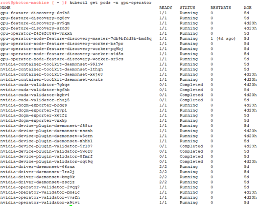
11. Confirm the license is valid:
ctnname=`kubectl get pods -n gpu-operator | grep driver-daemonset | head -1 | cut -d " " -f1`

kubectl -n gpu-operator exec -it $ctnname -- /bin/bash -c "/usr/bin/nvidia-smi -q | grep -i lic"
Verifying the Installation of GPUDirect with RDMA
During the installation, the NVIDIA driver daemonset runs an init container to wait on the Mellanox OFED (MOFED) drivers to be ready. This init container checks for Mellanox NICs on the worker node and ensures that the necessary kernel symbols are exported MOFED kernel drivers. After the verification is complete by the init container, the nvidia-peermem-ctr container is started inside each driver pod. At this point of the guide, we have not started installing the network operator so the init container will keep waiting for pods enabled with MOFED.
Confirm that the pod template for the driver daemonset includes the mofed-validation init container and the nvidia-driver-ctr and nvidia-peermem-ctr containers:
kubectl describe ds -n gpu-operator nvidia-driver-daemonsetmofed validation container:

nvidia-driver-ctr and nvidia-peermem-ctr containers

NVIDIA Network Operator Step-by-Step Installation Process
1. Start by labeling our worker nodes with the label "worker", list your nodes on the Tanzu Cluster:
kubectl get nodes -o wide2. Label your nodes with the following command:
kubectl label node tkc02-nodepool-a100-vgpu-vf-7p5p5-54c9b4dd5-7nbmk node-role.kubernetes.io/worker=workerConfirm that the nodes are labeled:
kubectl get nodes -o wide
3. After the nodes are labeled, we need to create a namespace for NVIDIA's network operator:
kubectl create namespace nvidia-network-operator
4. Now create a secret on the namespace that was just created, this will allow to pull the network operator images while doing the installation via helm:
kubectl create secret docker-registry ngc-image-secret -n nvidia-network-operator --docker-server=nvcr.io --docker-username='$oauthtoken' --docker-password='YOUR NVIDIA API KEY' --docker-email='YOUR NVIDIA NGC EMAIL'Check out the network operator values.yaml file that provides specific customizations for the network operator helm chart.
As you can see, we use the secret that we just created before in this values YAML file. For more information about the options on this file and values files for other NVIDIA network operator use cases, consult NVIDIA’s documentation.
5. Create the values YAML file:
touch values.yaml6. Now create the NVIDIA repo:
helm repo add nvidia https://helm.ngc.nvidia.com/nvidia  \

--username='$oauthtoken' --password=${NGC_API_KEY} \

&& helm repo update
7. Once created, we will install the helm chart, we will specify the latest version at the time of writing (1.23.5) and the values.yaml file as input:
helm install network-operator nvidia/network-operator -n nvidia-network-operator --create-namespace --version v23.5.0 -f values.yaml --debug8. Verify that the chart is showing as installed:
helm list -A
The creation of the pods that are part of the NVIDIA network operator takes 10 to 15 minutes; you can monitor the process with:
watch kubectl get pods -n nvidia-network-operatorA successful installation of the network operator should be like this:

9. After deployment, the network operator should be configured, and Kubernetes networking is deployed to use it in pod configuration. host-device-net.yaml is the configuration file for such a deployment, this custom resource creates a hostdev custom resource that can be requested while creating a pod, keep in mind that the Whereabouts ipam configuration can be customized to meet your needs, see the host-device-net.yaml file that you need to create.
10. Apply the YAML file:
kubectl apply -f host-device-net.yamlOnce applied confirm that the custom resource was created successfully:
kubectl get HostDeviceNetwork
11. We can now confirm that the nvidia-peermem-ctr container has successfully been loaded the nvidia-peermem kernel module:
kubectl logs -n gpu-operator ds/nvidia-driver-daemonset -c nvidia-peermem-ctr
Virtual Function Verification and Testing Process
At this point everything that is required to test this setup is ready, we will start by creating two pods and use this YAML file as an example (change the name of the pod for each one such as hostdev-test-pod1 and hostdev-test-pod2):
Key points in this YAML:
- We are using an image from docker hub, you can access that image by creating a secret with docker hub credentials, keep in mind the free account limits.
- A hostdev device request for a VF from our SRIOV enabled Mellanox NIC is used.
- A GPU is being requested and GPU operator gets know that it should install the NVIDIA drivers on it. The vGPU, MIG, and passthrough are configured on the VM class.
Create two pods, remember to change the name of the second pod so the result would be something like the following:
kubectl get pods

# NAME                  READY   STATUS      RESTARTS    AGE

# hostdev-test-pod-1    1/1     Running     0           4s

# hostdev-test-pod-2    1/1     Running     0           20s
After the pods are created, connect to a bash prompt with the following command:
kubectl exec -it hostdev-test-pod-1 -- bashConfirm that both pods can see the VF using lspci:

Verify that the vGPU, MIG, or Passthrough device is detected by the nvidia-smi command:

After verifying that our pods have access to the high-speed network interface and the NVIDIA GPU we can now perform and ib_write_bw (InfiniBand write bandwidth) test, this tool is part of perftest package. Perftest is a collection of tests written over uverbs intended for use as a performance micro-benchmark. The tests may be used for tuning as well as for functional testing.
Open a bash shell on both containers:
# Example

kubectl exec -it hostdev-test-pod-1 -- bash

kubectl exec -it hostdev-test-pod-2 -- bash
Get the IP address assigned to the secondary network interface backed by the Mellanox VF, the IP address for this network interface is defined based on the whereabouts config specified for the HostDeviceNetwork resource created before:
# Get the host IP address

ip a s
net1 is the secondary interface, this specific pod has IP 192.168.3.227. You can confirm that your interface is up and running with the following command:
rdma link![]()
Now we will proceed to run an ib_write_bw test, enter the following command on pod1, this first pod will serve as the server:
ib_write_bw -F -d mlx5_0 --report_gbits![]()
On the second pod enter the following command, this second pod will serve as the client:
ib_write_bw -F 192.168.3.227 -d mlx5_0 --report_gbitsThe result should look very similar to the following image, the output is reporting the maximum supported bandwidth:

GPUDirect Function Verification and Test Process
We have verified that all the required components from the GPU operator as well as our SRIOV VF are working properly, we leverage the two pods that were previously created to perform a test using Perftest's ib_write_bw, this time we enable CUDA as part of the test.
Get a bash shell to both containers:
kubectl exec -it hostdev-test-pod-1 -- bash

kubectl exec -it hostdev-test-pod-2 -- bash
Run the following command on the first container:
ib_write_bw -d mlx5_0 -a -F --report_gbits -q 1 --use_cuda=0
The flag "–use_cuda=0" will initialize a CUDA CTX (context) on the GPU 0 (you can confirm the available GPUs and their IDs with nvidia-smi).
On container two, run the following command:
ib_write_bw -d mlx5_0 -a -F --report_gbits -q 1 192.168.3.227 --use_cuda=0The result looks like the following on the server side (pod one):

NVIDIA vGPU Driver Step-by-Step Installation Process
We demonstrate the NVIDIA vGPU driver installation process as follows:
1. After SSH into the VM, update the system and install the dependencies.
sudo apt update && sudo apt upgrade -y
sudo apt install build-essential -y
sudo reboot
2. Get the driver installation file, change the permission and install the driver.
wget http://x.x.x.x/NVIDIA-Linux-x86_64-525.105.17-grid.run

chmod +x NVIDIA-Linux-x86_64-525.105.17-grid.run

sudo ./NVIDIA-Linux-x86_64-525.105.17-grid.run
3. Verify if vGPU driver is successfully installed.
nvidia-smi4. Get the license token, place into /etc/nvidia/ClientConfigToken, change permission and restart NVIDIA Grid Service
cd /etc/nvidia/ClientConfigToken/

sudo wget http://x.x.x.x/client_configuration_token.tok

sudo chmod 744 /etc/nvidia/ClientConfigToken/client_configuration_token.tok

sudo systemctl restart nvidia-gridd
5. Verify if the vGPU driver is successfully licensed.
nvidia-smi -q | grep -i lic
[1] This setting is automatically configured by Tanzu VM service when a VM class with GPUs is used.
[2] 128 or multiple of the GPU memory size