This post describes Primary Synchronization Signal(P-SS) and Secondary Synchronization Signal(S-SS) sequences used in LTE system.It provides comparison between P-SS and S-SS as per LTE standard.
In LTE, there are two downlink synchronization signals which are used by the UE to obtain the cell identity and frame timing.
- Primary synchronization signal (PSS)
- Secondary synchronization signal (SSS)
The division into two signals is aimed to reduce the complexity of the cell search process.
Cell Identity Arrangement
The physical cell identity, NcellID, is defined by the equation:
NCELLID=3N(1)ID+N(2)ID
- N(1)ID is the physical layer cell identity group (0 to 167).
- N(2)ID is the identity within the group (0 to 2).
This arrangement creates 504 unique physical cell identities.
From here we can know that the range of PCI for LTE Cell is from 0 to 503.
Synchronization Signals and Determining Cell Identity
The primary synchronization signal (PSS) is linked to the cell identity within the group (N(2)ID).
The secondary synchronization signal (SSS) is linked to the cell identity group (N(1)ID) and the cell identity within the group (N(2)ID).
You can obtain N(2)ID by successfully demodulating the PSS. The SSS can then be demodulated and combined with knowledge of N(2)ID to obtain N(1)ID. Once you establish the values of N(1)ID and N(2)ID, you can determine the cell identity (NcellID).
Primary Synchronization Signal (P-SS) Sequences
• Three PSS sequences are used in LTE, corresponding to the three physical layer identities within each group of cells.
• The PSS is constructed from a frequency-domain ZC sequence of length 63.
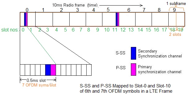
• Transmitted on 6th symbol of slot 0 and slot10 of each radio frame on 72 subcarriers centered around DC.
• The PSS is constructed from a frequency-domain ZC sequence of length 63.
• Transmitted on 6th symbol of slot 0 and slot10 of each radio frame on 72 subcarriers centered around DC.
Secondary Synchronization Signal (S-SS) Sequences
• SSC1 and SSC2 are two different cyclic shifts of a single length-31 M sequence.
• Each SSS sequence is constructed by interleaving, in the frequency-domain, two length-31 BPSK-modulated secondary synchronization codes
• Two codes are alternated between the first and second SSS transmissions in each radio frame
• This enables the UE to determine the 10 ms radio frame timing from a single observation of a SSS
• Transmitted on 5th symbol of slot 0 and slot10 of each radio frame on 72 subcarriers centered around DC.
| Signal | Full Form | Direction | Position | Modulation/ Coding scheme | Function |
|---|---|---|---|---|---|
| P-SS | Primary Synchronization Signal | Downlink | 6th symbol of slot 0 and slot 10(time axis) mapped on 72 subcarriers centered around DC(frequency axis) | Zadoff Chu sequence of length 63 | UE first finds the primary synchronization signal (PSS) which is located in the last OFDM symbol of first time slot of the first and 5th sub-frames This enables UE to be synchronized on sub-frame level Primary Synchronization Signal helps for Slot Timing Detection and Physical Layer ID (0,1,2) detection |
| S-SS | Secondary Synchronization Signal | Downlink | 5th symbol of slot 0 and slot 10(time exis) mapped on 72 subcarriers centered around DC(frequency axis) | BPSK modulated length-31 M sequence | From SSS, UE is able to obtain physical layer cell identity group number (0 to 167) It helps for Radio Frame Timing detection, find Physical Layer Cell ID, cyclic prefix length detection, FDD or TDD detection |
No comments:
Post a Comment